1
Service Instructions
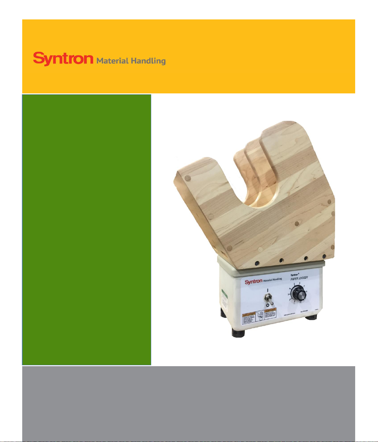
SyntronJogger
Model: J-I-D
Contents Page
Introduction 1
Installation 2
Operation 2
Maintenance 2
Trouble Shooting 3
Parts List 4
Syntron Material Handling, LLC. reserves the right to make changes at any time, without notice and without
any liability or other obligation on its part, in materials, equipment, specifications and models, and also to
discontinue the manufacture and sale of models and the parts and components thereof. For further detailed
information, contact Syntron Material Handling, LLC.
Safety Instructions: Product safety labels must be highly visible on the equipment. Establish a regular
schedule to check visibility. Should safety labels require replacement, contact Syntron Material Handling, LLC.
for an additional supply free of charge.
INTRODUCTION
The SyntronElectromagnetic Jogger, Model J-I-D is used for jogging and packing of materials. A magnet
assembly produces a vibrating action, which is transmitted to the deck or rack through a system of leaf springs.
Refer to these service instructions prior to installing, adjusting, or performing maintenance on this
jogger.
WARNING: Failure to follow these instructions could result in unsatisfactory jogger performance, damage
or shortened service life, or personal injury.
Inspect the jogger for damage which may have occurred during shipment. If any damage is found, immediately
notify the shipping carrier and Syntron Material Handling, LLC..
Unauthorized modifications to the jogger may present a safety hazard to the operator and void the warranty.
Modifications or additions to the jogger should not be made without first consulting Syntron Material Handling,
LLC.
The jogger weighs approximately 25 pounds and must be lifted by the base only. The voltage and frequency of
the power supply must be as specified on the nameplate. The power supply of another rating may cause
damage to the unit.
INSTALLATION