Syntron Material Handling V-75-A Operating instructions

Service
Instructions
Syntron
®
Electromagnetic
Vibrators
Model: V-75-A

1
Service Instructions
Syntron® Electromagnetic
Vibrator
Model : V-75-A
SMH reserves the right to alter at any time, without
notice and without liability or other obligations on its
part, materials, equipment specifications, and models.
SMH also reserves the right to discontinue the
manufacture of models, parts, and components
thereof..
Safety instruction: Products Safety Labels must remain highly visible on the equipment. Establish a
regular schedule to check visibility. Should safety labels require replacement, contact SMH for an
additional supply free of charge.
INTRODUCTION
The Model V-75-A is a solid impacting electro-magnetic vibrator designed to promote the free flow of bulk
materials through a straight-line vibratory action. This action is transmitted to the installation through the
vibrator base.
The vibrator is operated from a single-phase R-C power supply using a standard controller.
INSTALLATION
The vibrator may be installed in any position with the long axis on a vertical plane.
The base is provided with four 11/16” diameter mounting holes. Four mounting bolts must be used and the
bolts must be securely tightened. Check frequently to see that these bolts remain tight.
If rigid conduit is used between the controller and vibrator, provide at least 18” of flexible cable between the
vibrator and conduit.
The current supply must be the same as the rating designated on the nameplate.
Installation of the controller should be according to the controller instructions.
OPERATION
NOTE: If the vibrator is installed on a hopper, do not operate the vibrator while the hopper is closed. The
vibrating action will compact the contents of the hopper.
To start the vibrator, place the switch in the ”ON” position. The rheostat is used to control the force of the
vibration. Turning the control clockwise will increase the vibrator output and counterclockwise will decrease
the output. To stop the vibrator, place the switch in the ”OFF” position.

2
CAUTION: Excessive current draw is caused by too wide an air gap or too much spring tension,
resulting in heat build-up and blown fuses. Low current is caused by too narrow an air gap, resulting in
striking of the core and armature assemblies. Do not operate the vibrator while these conditions exist.
Refer to ”Vibrator Adjustment” below or contact SMH concerning spring adjustment.
MAINTENANCE
The vibrator and controller must be kept clean and all hardware must be kept tight.
Examine the leaf springs for defects. If defective, replace all springs. After replacing springs check the
current draw, an adjustment may be required. Refer to the vibrator adjustment instructions below.
VIBRATOR ADJUSTMENT
WARNING: The vibrator is adjusted while in operation. Use care to avoid electrical shock and
physical harm to personnel.
After installed and while operating, the current draw of the vibrator must not exceed the current ratings as
listed on page 3 of this manual. Check the current draw at the controller with a clamp-on amp meter. All
current must be taken at the controller.
To adjust the current draw of the vibrator, connect a clamp-on amp meter over ”L1” or ”L2” inside the
controller. While the vibrator is operating, loosen the lock nuts which are furthest from the coil spring (E).
Turn the hex nuts (closest to the coil springs) either up or down equally on each end of the vibrator until the
maximum efficiency is obtained, without exceeding the allowable amper rating.
IMPORTANT: When using a clamp-on meter to read the current of a vibrator the meter reading must
always be multipied by a factor of 1.7. Due to the waveform characeristics of the vibrator, the clamp-on
meter does not reveal the current rating as designated on the nameplate.
The vibrating action must be equal at the four corners of the vibrator. If there is a difference in the action of
the leaf springs at one end of the vibrator, tap the coil spring until it is centered and equal vibration is
obtained at each end of the vibrator.
When proper performance is obtained, lock the hex nuts in place. Remove clamp-on meter from the
controller and replace the controller cover. The vibrator is now ready for further operation.
LEAF SPRING REPLACEMENT
Defective or worn leaf springs must be replaced as they may cause a ”striking” condition. SMH
recommends replacing both leaf spring assemblies rather than only the defective springs.
To replace springs, work on only one end of the vibrator at a time. Remove hex nuts and cap screws which
secure springs to the vibrator. Remove springs, spacers, spring clamps and rubber transverse springs,
noting their position and arrangement. Insert new springs.After springs, spacers and clamps are installed,
replace the rubber transverse springs, replace hardware and tighten hex nuts to secure the spring
assembly. Follow this procedure on the opposite end of the vibrator.
After replacement of leaf springs, it is advisable to check the current rating. Refer to the vibrator adjustment
instructions in this manual.

3
If the current draw of the vibrator is the maximum allowable current rating (see page 3) and the vibrator is
not meeting the required capacity, a change in the installation may be necessary.
MAXIMUM CURRENT RATINGS: TROUBLE SHOOTING
16 Amps 115V-50/60Hz
8 Amps 230V-50/60Hz
4 Amps 460V-50/60Hz
10 Amps 115V-25Hz
5 Amps 230V-25Hz
3 Amps 460V-25Hz
Replace only with parts recommended, or supplied by SMH.
PARTS LIST – ELECTROMAGNETIC VIBRATOR MODEL: V-75-A
ITEM DESCRIPTION QTY PART NO.
A Armature Casting 1 C-57566-A
B Cap Screw, Hex Hd. (3/8”-16 x 2”) 4 H0310901
Lockwasher 3/8” 4 H0113201
Hex Nut (3/8”-16) 4 H0103001
C *Label (Disc. Electric.) 1 A-125694
D *Nameplate 1 A-61712
E Hex Jam Nut (7/8”-9) 8 H0106004
F Outside Spring Seat 4 A-14123
G Coil Spring 4 A-22237-A
H Inside Spring Seat 4 A-14010
J ●Strain Relief Tubing 1 A-14078
K ●Coil Cover (Cable Side) 1 C-14076-A
●Cable Bushing 1 A-14083
●Cap Screw Hex Soc. Hd. (3/8”-16 x 3/8”) 1 H0421400
●Lockwasher (3/8”) 2 H0113201
●Cap Screw, Hex Hd. (3/8”-16 x 1”) 2 H0310201
M Stud Assembly 2 B-192967-A
Elastic Stop Nut (5/8”-11) 2 H2100213
N Striking Plate Assembly 2 B-14169
P Core Assembly 1 C-58112
Core Insulating Sleeve (Not Shown) 1 B-14081
Q Cable Clamp 1 0198X002
Cap Screw, Hex Hd. (1/4”-20 x 3/4”) 1 H0301201
Plainwasher (1/4”) 1 H0116601
Lockwasher (1/4”) 1 H0112801
Hex Nut (1/4-20) 1 H0101601
R Coil & Cable Assembly (115V-50/60Hz) D-62396-C
Coil & Cable Assembly (230V-60Hz) 1 D-62396-D
Coil & Cable Assembly (460V-50/60Hz) Only D-62396-E
PROBLEM CAUSE CORRECTION
Vibrator Operates
Below Capacity
Loose Hardware
Defective Magnet
Defective Springs
Repair
Replace
Replace
Vibrator Does
Not Run
Loose Connections
in Controller
Defective Rheostat
Repair
Replace

4
Parts List cont.
ITEM DESCRIPTION QTY PART NO.
Coil & Cable Assembly (230V-50Hz) B-84834-B
Coil & Cable Assembly (115V-25Hz) B-84836-A
Coil & Cable Assembly (230V-25Hz) B-84903-B
Coil & Cable Assembly (460V-25Hz) B-84836-C
Coil Washer 1 A-13156
Lockwasher (#10) 1 H0112458
Mach. Screw, Rd. Hd., Br. (#10-32 x 3/8”) 1 H0203102
S Rubber Transverse Spring Spacer 4 A-15688
Ferrule 4 A-15682
T Leaf Spring 6 A-11483
U Leaf spring Clamp 2 224549-001
V ●Coil Cover (Opposite Cable Side) 1 B-12861-A
●Lockwasher (3/8”) 2 H0113201
●Cap Screw Hex Hd. (3/8”-16 x 1”) 2 H0310201
W Enclosure Assembly, Dust Tight Only (Not Shown) 1 D-160199-A
* Do not remove or paint over safety labels. Should safety labels require replacement, contact SMH for an
additional supply free of charge.

5
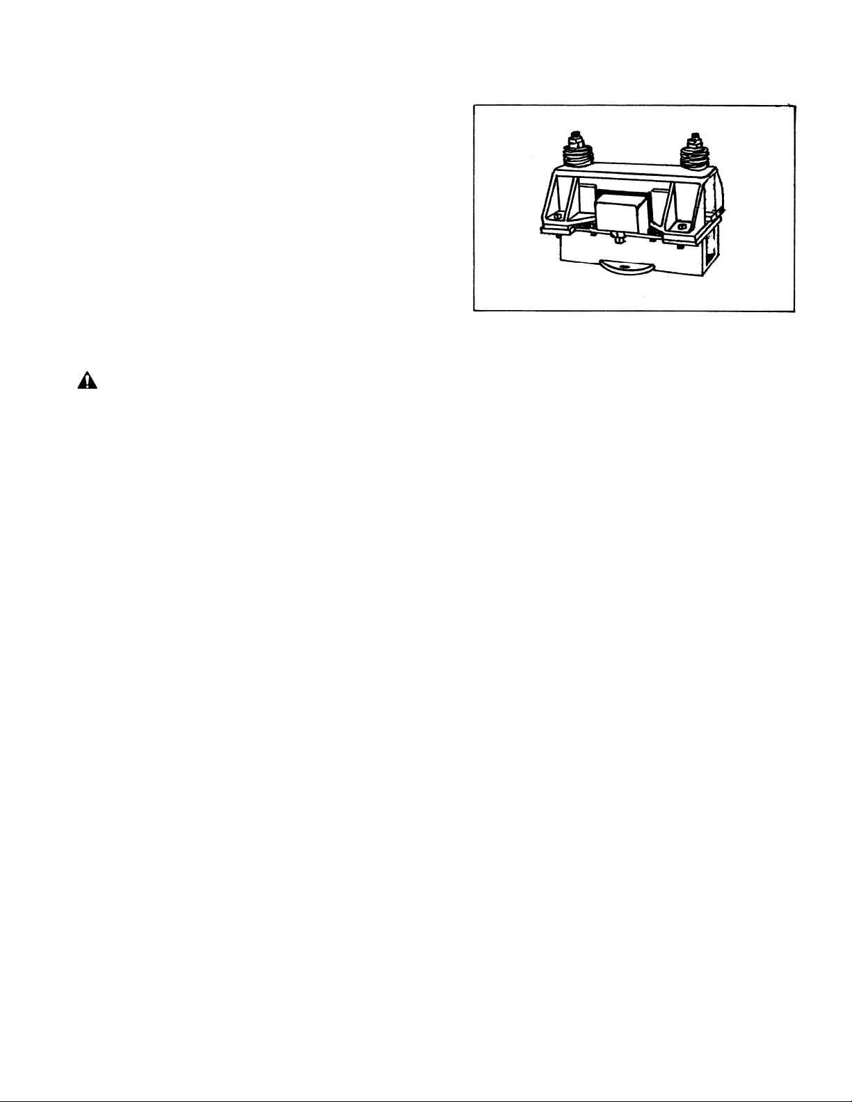
Mounting Electromagnetic Bin Vibrators
The correct location of electromagnetic vibrators is of prime importance in obtaining maximum efficiency from the
selected model.
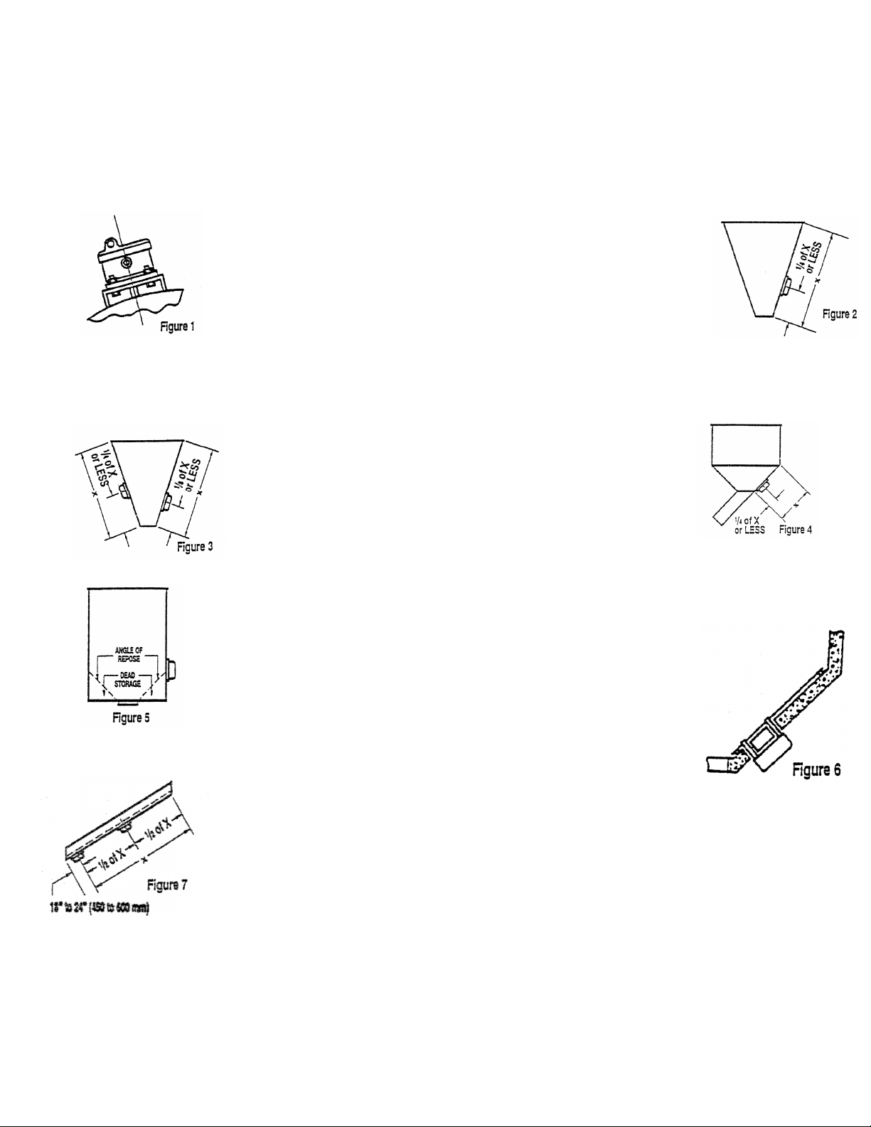
CURVED SURFACES Figure 1
Select a bracket made from a channel section or a bent plate when
mounting a vibrator to a curved surface. A center gusset is required for all
totally enclosed vibrators, and two blocks of sufficent height to contact the
curved surface are required for models V-75 and V-500. The selected gusset
or block must be securely welded to the bracket and curved surface. This
arrangement is required to stiffen the mounting and transmit vibrations
directly to the hopper contents. Mounting bolt heads can be welded to the
brackets underside.
CONICAL HOPPERS Figure 2 The vibrator should be bolted, as above, directly to the hopper face, 12 to 18 inches
(300 to 450mm0 or less from the discharge.
RECTANGULAR HOPPERS Figure 3
Mount each vibrator to the hopper wall the same as on a conical
hopper. If a stiffener obstructs mounting, mount the vibrator in the
middle of the panel next to the stiffener. A second vibrator, if required,
should be bolted on the opposite face at a slightly higher elevation.
HOPPER WITH SLOPING DISCHARGE Figure 4 Mount the vibrator
on the centerline of the hopper, as close to the discharge as possible. An additonal vibrator
may be required on the discharge chute.
RECTANGULAR OR CYLINDRICAL BINS WITH FLAT BOTTOM DISCHARGE Figure 5
Mount directly to the side of the bin, just below the point where the materials’ natural angle of
repose intersects the side, as shown in the sketch.
CONCRETE OR WOODEN HOPPER Figure 6 If a wooden hopper is lined
with thin sheet, the vibrator mounting bolts must attach to the lining.
Ina concrete hopper, a steel plate, secured across the top, should be placed
vertically from the discharge opening inside the hopper, along the side to
which the vibrator will be mounted. At about one-quarter or less of the
distance from the discharge to the vertical side, an opening should be cut (or allowed for in the
hopper construction plans) to permit bolting the vibrator to the steel plate.
INCLINED CHUTES Figure 7 Chutes less than 10 to 12 feet (3 to 3.6 m) long are usually
equipped with just one vibrator located considerably below center. Allow for the vibrator to be
moved about one foot in either direction.
On chutes requiring more than one vibrator, the first one should be located 18 to 24 inches
(450 to 600 mm) from the outlet. The second unit should be mounted about half way between
this vibrator and the upper end.
NOTE: Vibrators on hoppers should operate only when the hopper is open to to flow.
Otherwise, vibrations may pack the hopper contents.

Corporate Office
P. . Box 1370
Tupelo, Mississippi 38802
Phone: 662.869.5711
Fax: 662.869.7449
Tupelo
2730 Hwy 145 South
Saltillo, Mississippi 38866
Phone: 662.869.5711
Fax: 662.869.7493
Toll Free:
800.356.4898
info@syntronmh.com
Changshu
#2 Road No. 1
Changshu Export Processing Zone
Changshu, Jiangsu, China 215513
Phone: +86 0512.52299002
Fax: +86 0512.52297228
info@syntronmh.com
Form No. SM0354_071917 Printed in U.S.A
Table of contents
Other Syntron Material Handling Industrial Equipment manuals