Master Language is English Hot Runner System Installation Guide SVC-17-0001_EN-Rev11
RESTRICTED: Property of Synventive. - 275 - All rights reserved. Errors and omissions excepted
For limited third party distribution based on need and intended use. © 2019 Synventive Molding Solutions
H O T R U N N E R T E C H N O L O G Y
Hot Runner System Installation Guide
Service and Maintenance / Nozzle 06E Series
10.1.1.2 Disassembly the Nozzle 06E
Disassembling the Nozzle Tip
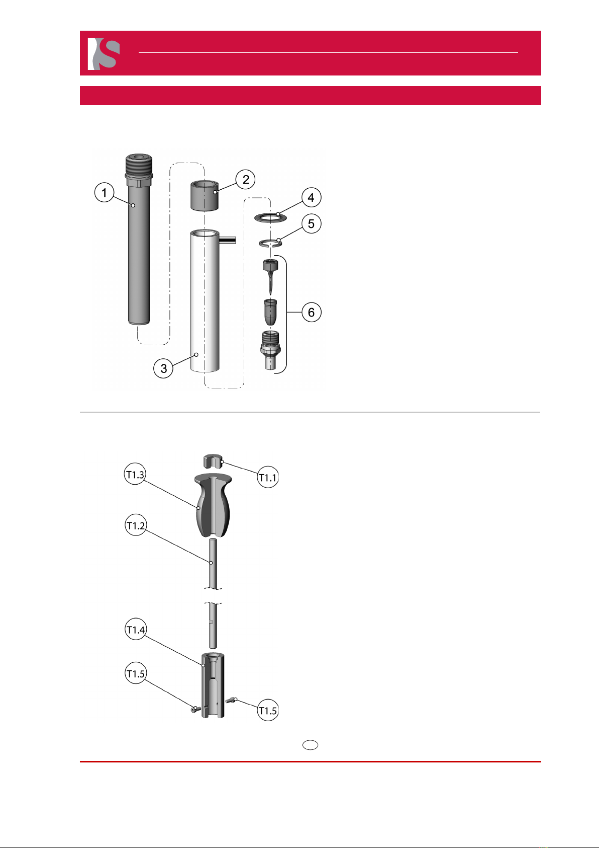
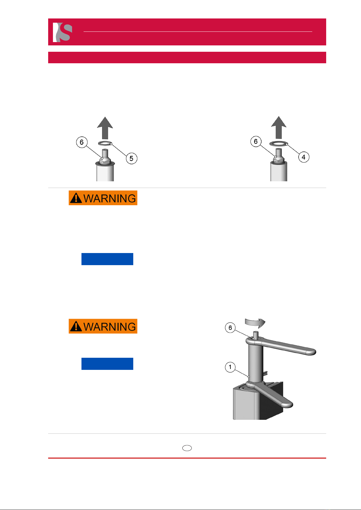
1) Remove the circlip (5) from the nozzle tip (6).
Doc006490.png
2) Remove the component ring version 02(4)
Doc006489.png
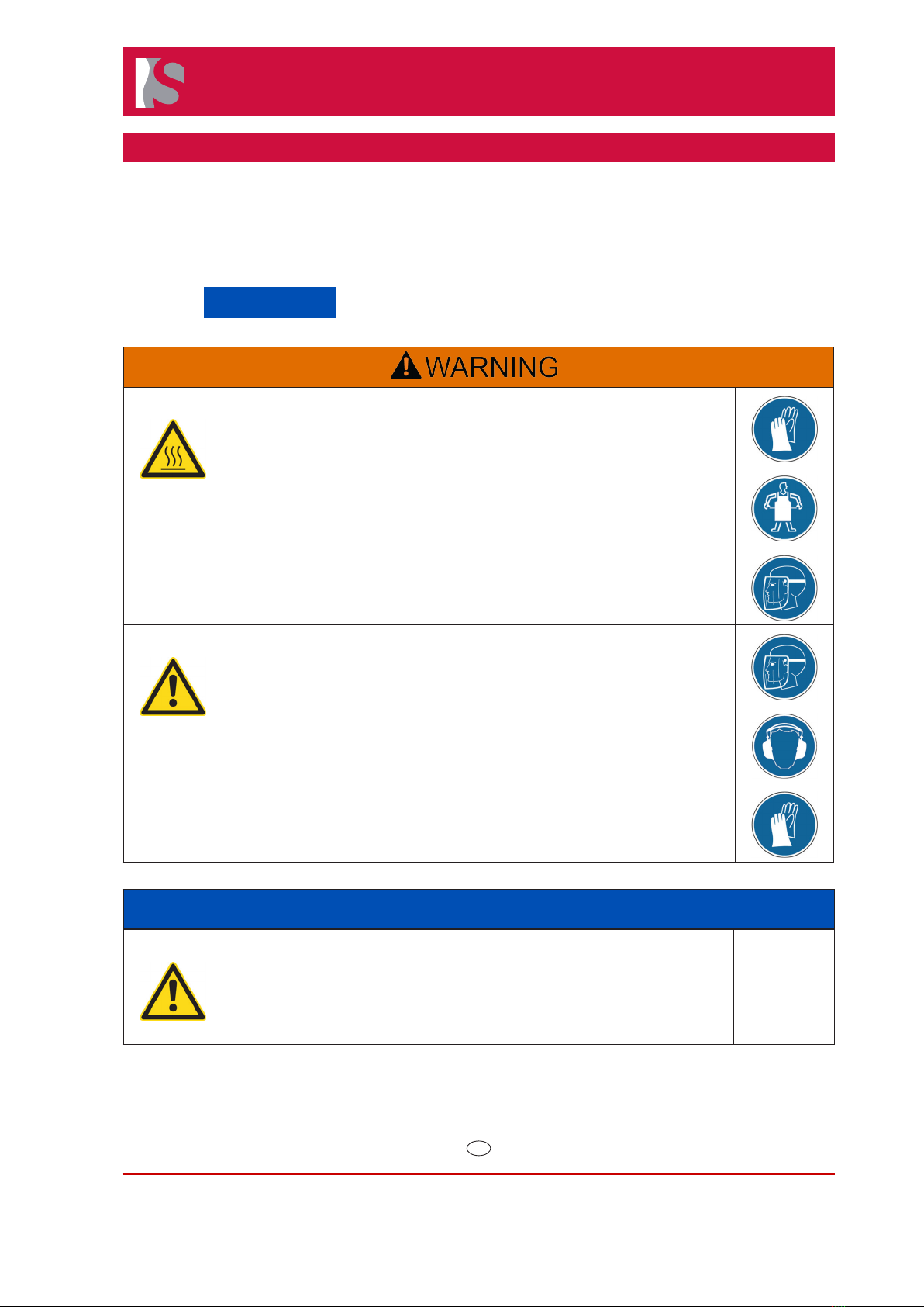
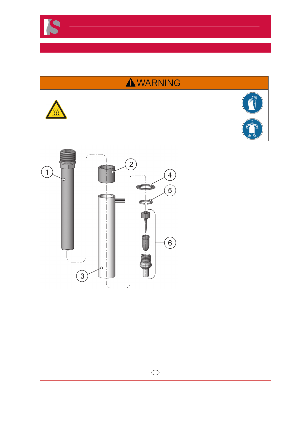
Hot Surfaces Hazard
Following works must be carried out by qualied persons.
Use personal protective equipment, such as gloves, apron, sleeves
and face protection, to guard against burns
Contact between the skin and the hot nozzle could result in burns.
NOTICE
To dismount the nozzle tip from the nozzle, if there is plastic
material in the nozzle, the tip must be heated-up.
Never use an acetylene or welding torch, as severe nozzle
damage can occur from over-heating.
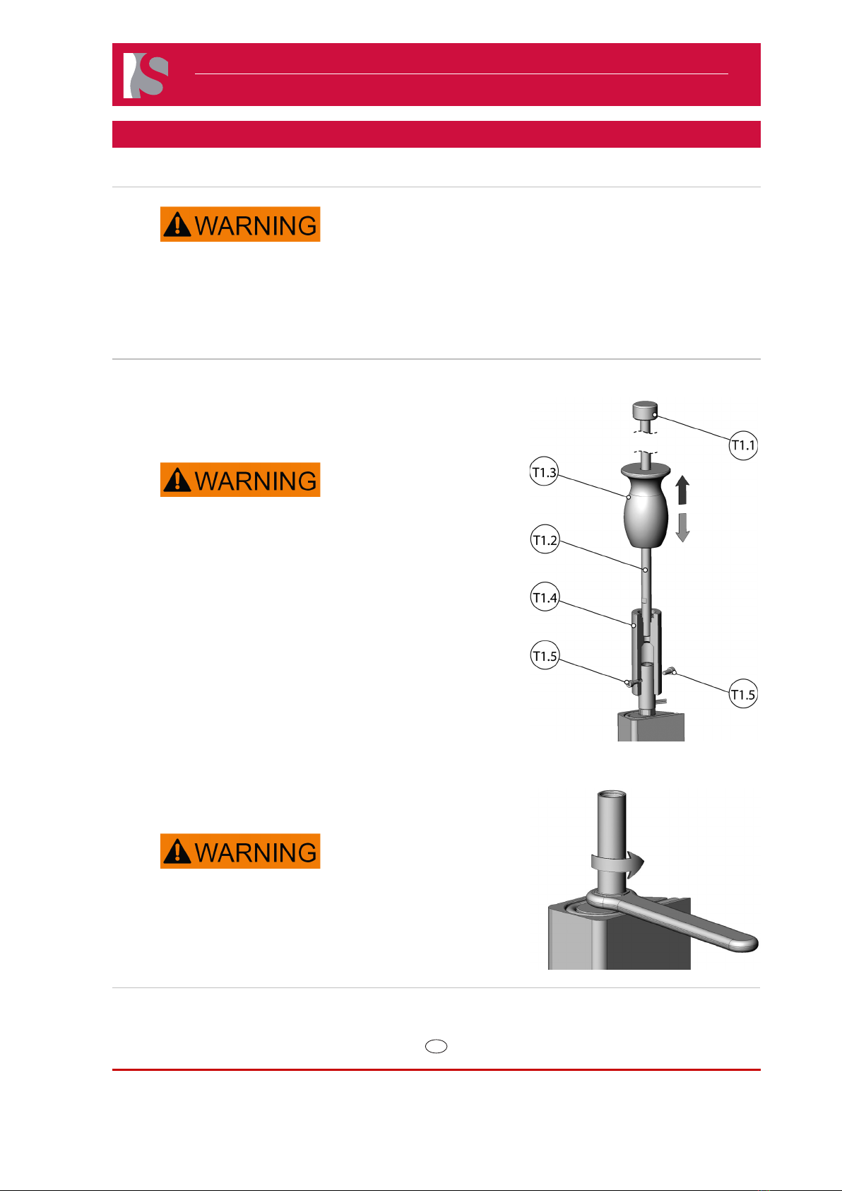
3) Heat the nozzle tip (2) using a heat gun to the maximum temperature of
200 °C (392 °F).
Hot Surfaces Hazard
The nozzle is still hot.
NOTICE
Unscrewing the nozzle tip may cause the nozzle to start
rotating together with the nozzle tip, which could result in
leakage at the base of the nozzle.
4) Hold the nozzle body (1) rmly using an engineer’s wrench at the
hexagonal shape.
5) Unscrew the nozzle tip (6) from the nozzle body (1) using an
engineer’s wrench. Doc006494.png