Synventive HB Series User manual

EN
Master Language is English Hot Runner System Installation Guide SVC-17-0001_EN-Rev13
RESTRICTED: Property of Synventive. - 85 - All rights reserved. Errors and omissions excepted
For limited third party distribution based on need and intended use. © 2021 Synventive Molding Solutions
H O T R U N N E R T E C H N O L O G Y
Hot Runner System Installation Guide
Service and Maintenance / Actuator HB Series
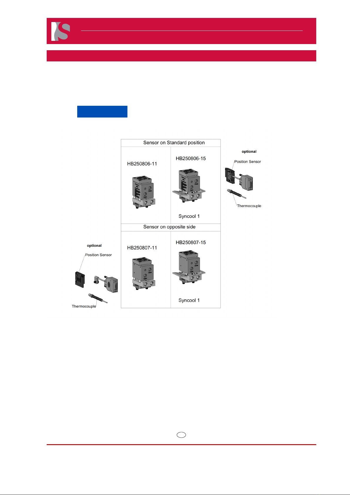
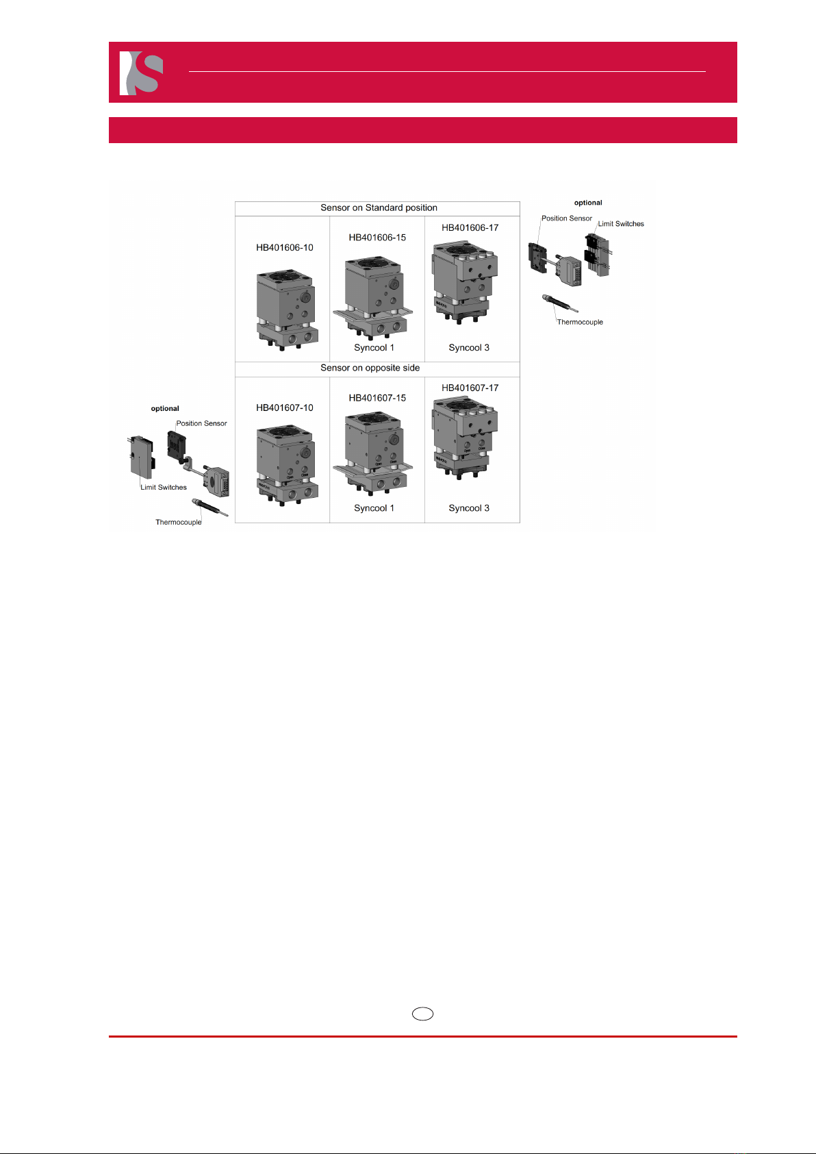
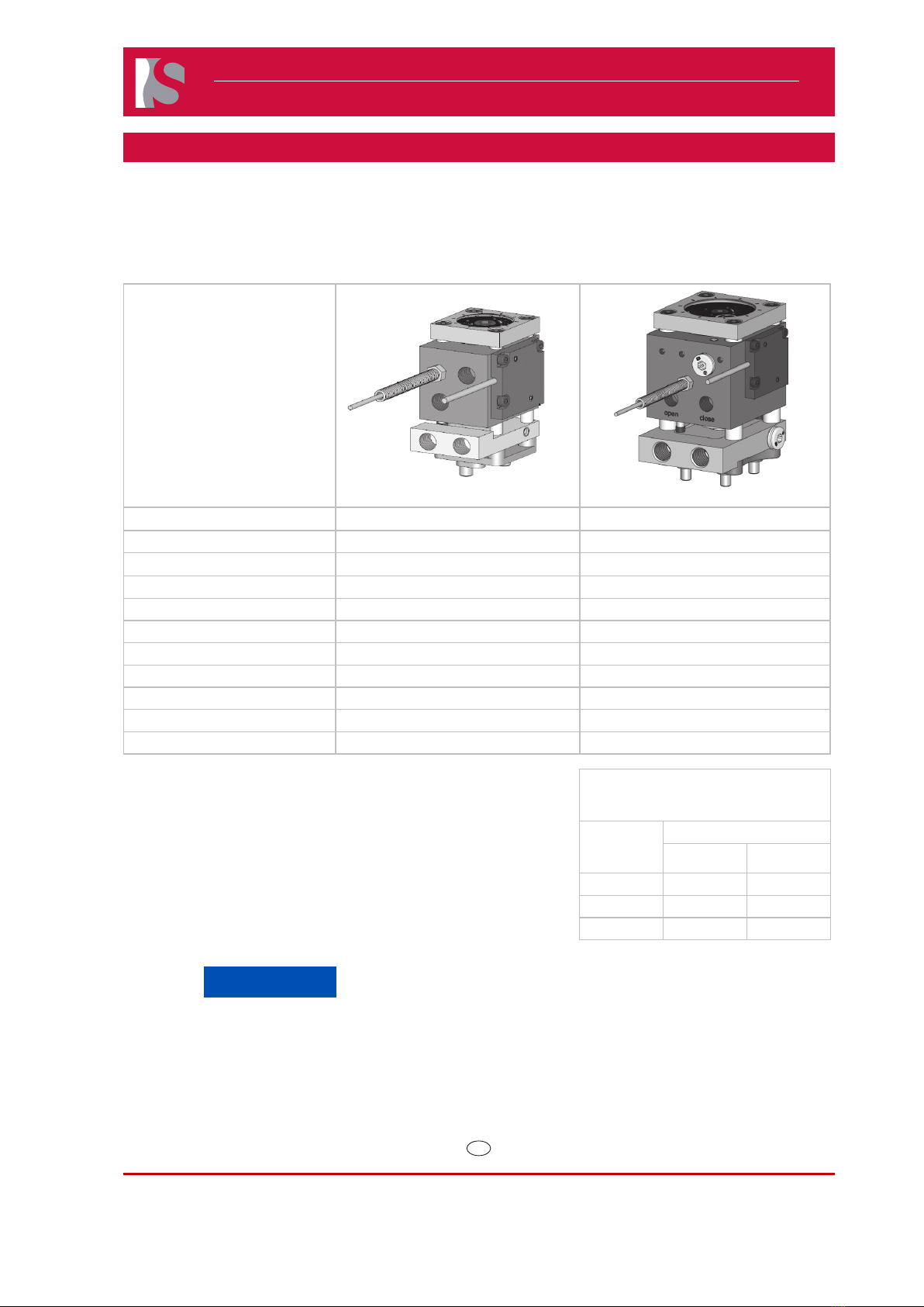
8.1.1 Actuator HB Series
8.1.1.1Technical Data
Doc006521.png Doc006419.png
Parameters HB2508# HB4016#
Valve Pin Diameter 3 mm, 3.8 mm 5 mm, 6 mm, 8 mm, 12 mm
Nozzle Series 06E, 09E 12E, 16E, 22E
Pin Adjustment +/- 1 mm +/- 1.5 mm
MIn/Max Close Forces 1963/2945N 5027/7540N
Min/Max Open Forces 443/2267N 3506/5259N
Min/Max. Hydraulic Pressure 40/60 bar (600/870 psi) 40/60 bar (600/870 psi)
Valve Pin Stroke 8 mm 16 mm
Hydraulic Connections M10x1.0 M10x1.0
Cooling Temperature 30-60°C 30-60°C
Cooling Connections M10x1.0 M12x1.5
Recommended HB4016 Actuator Pressure
Settings when Hydraulic Manifold Block
is not Supplied on Hot Runner
Pin
Diameter
(mm)
Actuator Pressure
PSI Bar
5 300 20
Thermocouple and Position Sensor optional on all models.
Maximum 3 Actuators per cooling zone on all models.
6 450 30
8 & 12 600 40
NOTICE
To ensure long life and continued flawless operation of the actuator, we recommend using a service
medium that complies with the requirements of classification 21/18/13 pursuant to ISO 4406.
The coolant should be properly modified e.g. filtered water with an anti-corrosion and frost proof agent.
After switching off the Hot Runner heater, the cooling for the actuator should remain on for at least
15 minutes, to avoid damage to the Actuator seals and the position sensor.

EN
Master Language is English Hot Runner System Installation Guide SVC-17-0001_EN-Rev13
RESTRICTED: Property of Synventive. - 86 - All rights reserved. Errors and omissions excepted
For limited third party distribution based on need and intended use. © 2021 Synventive Molding Solutions
H O T R U N N E R T E C H N O L O G Y
Hot Runner System Installation Guide
Service and Maintenance / Actuator HB Series
8.1.1.2Overview of the described actuators
This manual describes the assembly process to build the HB Series Actuators. The Actuator parts are
identied with the numbers indicated in the following gure, which shows the components.
NOTICE
Always tighten the screws to the torques specified in the respective table in section 13.
Doc008513.png

EN
Master Language is English Hot Runner System Installation Guide SVC-17-0001_EN-Rev13
RESTRICTED: Property of Synventive. - 87 - All rights reserved. Errors and omissions excepted
For limited third party distribution based on need and intended use. © 2021 Synventive Molding Solutions
H O T R U N N E R T E C H N O L O G Y
Hot Runner System Installation Guide
Service and Maintenance / Actuator HB Series
Doc008514.png

EN
Master Language is English Hot Runner System Installation Guide SVC-17-0001_EN-Rev13
RESTRICTED: Property of Synventive. - 88 - All rights reserved. Errors and omissions excepted
For limited third party distribution based on need and intended use. © 2021 Synventive Molding Solutions
H O T R U N N E R T E C H N O L O G Y
Hot Runner System Installation Guide
Service and Maintenance / Actuator HB Series
8.1.1.3HB Series assemblies
The picture shows the HB401606-10 as example.
Doc008515.png

EN
Master Language is English Hot Runner System Installation Guide SVC-17-0001_EN-Rev13
RESTRICTED: Property of Synventive. - 89 - All rights reserved. Errors and omissions excepted
For limited third party distribution based on need and intended use. © 2021 Synventive Molding Solutions
H O T R U N N E R T E C H N O L O G Y
Hot Runner System Installation Guide
Service and Maintenance / Actuator HB Series
8.1.1.4HB Series seal kits
The picture shows the housing complete from actuator HB401606-10 as example.
Doc008516.png
At service, the parts from the seal set should be replaced.
Seal kit
HB250806-11
HB250806-15
HB250807-11
HB250807-15
HB401606-10
HB401606-15
HB401606-17
HB401607-10
HB401607-15
HB401607-17
Item Description Qty Item Qty Item
1 Seal Kit 1 SKT2508 1 SKT4016
1.1 Piston Seal 1 2G0/25-19-2.9 1 K30-40-40-32-3.2
1.2 Guiding Element 1 15.2X12X1.6/1.6 1 FB2.3-1.5L70.5
1.3 O-Ring Seal 1 VIOR-21.95X1.78-FPM-
75-G
1 VIOR-35X2.28-FPM-80-G
1.4 Rod Seal 1 C1-1028-V3664 1 C1-2038-V3664
1.5 Retaining Ring 1 DIN472-27X1,2 1 DIN472-42X1,75
1.6 Restrictor 1 EIS-TM-04-010 1 EIS-TM-04-010
NOTICE
1) All components must be cleaned (and oil free) prior to beginning assembly process.
2) All Seals and O-rings must be lubricated prior to installation.
3) This procedure is intended for use together with HCO-HB####-##, HB######-## drawings.

EN
Master Language is English Hot Runner System Installation Guide SVC-17-0001_EN-Rev13
RESTRICTED: Property of Synventive. - 90 - All rights reserved. Errors and omissions excepted
For limited third party distribution based on need and intended use. © 2021 Synventive Molding Solutions
H O T R U N N E R T E C H N O L O G Y
Hot Runner System Installation Guide
Service and Maintenance / Actuator HB Series
8.1.1.5HB assembly tools
These tools are needed for assembly and service of the Actuator. The tools are identied with the
numbers indicated in the following gure.
No. Description Figure HB2508 HB4016
T3 Valve pin disassembly tool
Doc001229.tif
ATCYL0805 ATCYL0303
T4 Piston seal installation cone
Doc006650.png
ATCYL0203 ATCYL0304
T5 Piston seal spread tube
Doc006651.png
ATCYL0202 ATCYL0105
T6 Piston seal calibration sleeve
Doc006652.png
ATCYL0204 ATCYL0107
T9 Piston and cap assembly tool
Doc006653.png
ATCYL45 ATCYL27
T10 Dowel insertion tool
Doc006654.png
ATCYL48 ATCYL49
T11 Top CV plug assembly tool
Doc006655.png
Tool not needed ATCYL40
T13 CV Plug Tool
Doc006657.png
EIS-HT-050 EIS-HT-050
T14 Adjustment Tool
Doc006420.png
ATA01 ATA01
T15 Piston Cap Tool
Doc008087.png
AT-PIC25010
AT-PIC2502
AT-PIC4001
AT-PIC4002

EN
Master Language is English Hot Runner System Installation Guide SVC-17-0001_EN-Rev13
RESTRICTED: Property of Synventive. - 91 - All rights reserved. Errors and omissions excepted
For limited third party distribution based on need and intended use. © 2021 Synventive Molding Solutions
H O T R U N N E R T E C H N O L O G Y
Hot Runner System Installation Guide
Service and Maintenance / Actuator HB Series
8.1.1.6Dismounting the Actuators of the HB Series
Danger to Life by Hydraulics
Serious personnel injury or death can result from connecting or
disconnecting hydraulic hoses under pressure.
Hydraulic works must be carried out by qualied persons.
Use personal protective equipment, such as face protection, headgear, anti oil
gloves.
The hoses in Hot Runner Systems and the injection mold are under high
pressure and high temperatures.
Before disconnecting or connecting any Hydraulic hoses:
●The injection machine / hydraulic pump must be shut down.
●The electrical disconnect properly locked out.
●Pressure from the hoses must be removed.
For rst aid contact your medical / safety representing
Dismounting Procedure
1) Locate and remove the four screws (F) on
top of the actuator housing (A).
2) Push the whole actuator housing (A) in
the direction specied on the pin release
indicator label (I).
This will disengage the actuator from the
valve pin.
Doc006358.png

EN
Master Language is English Hot Runner System Installation Guide SVC-17-0001_EN-Rev13
RESTRICTED: Property of Synventive. - 92 - All rights reserved. Errors and omissions excepted
For limited third party distribution based on need and intended use. © 2021 Synventive Molding Solutions
H O T R U N N E R T E C H N O L O G Y
Hot Runner System Installation Guide
Service and Maintenance / Actuator HB Series
3) Lift the entire actuator housing (A) out of the
assembly. Removal of the cooling plate (B)
is not required when removing the actuator
housing assembly.
Doc006356.png
4) Unscrew and remove the M6 socket head
cap screws (R).
5) Lift out the mounting plate (S).
Doc006357.png
8.1.1.7Seal Replacement
Disassembly
1) Remove Snap Ring (A).
LETTER PART
1.1 Piston Seal
1.2 Guiding Element
1.3 O-Ring Seal
1.4 Rod Seal
1.5 Retaining Ring
1.6 Restrictor
Doc008517.png

EN
Master Language is English Hot Runner System Installation Guide SVC-17-0001_EN-Rev13
RESTRICTED: Property of Synventive. - 93 - All rights reserved. Errors and omissions excepted
For limited third party distribution based on need and intended use. © 2021 Synventive Molding Solutions
H O T R U N N E R T E C H N O L O G Y
Hot Runner System Installation Guide
Service and Maintenance / Actuator HB Series
2) Remove piston (E) and cap (F) with a valve
pin.
Doc008518.png
3) Separate piston (E) from cap (F).
Doc008505.png
4) Use tools T15.1 and T15.2 to disassemble the
piston cap PC02 from PC01.
5) Remove Rod Seal 1.4.
Doc008506.png

EN
Master Language is English Hot Runner System Installation Guide SVC-17-0001_EN-Rev13
RESTRICTED: Property of Synventive. - 94 - All rights reserved. Errors and omissions excepted
For limited third party distribution based on need and intended use. © 2021 Synventive Molding Solutions
H O T R U N N E R T E C H N O L O G Y
Hot Runner System Installation Guide
Service and Maintenance / Actuator HB Series
6) Dismount seals:
●Piston Seal (1.1)
●Guiding Element (1.2)
●O-Ring Seal (1.3)
●Rod Seal (1.4)
7) After disassembly of the sealing elements,
the original seals must be replaced. See the
following sections for additional details.
Doc008507.png
8.1.1.8Cooling Plate Maintenance
Cooling Plate Removal
1) With the actuator dismounted, lift up the cooling
plate (2).
Doc006359.png
Cleaning the Cooling Plate
Removing the cooling plate plug
(VSTI10X10RVITCF) facilitates the cleaning of the
cooling plate.
1) Remove the cooling plate plug (3 ) with a HEX5
wrench.
2) Clean the cooling plate (2).
3) Replace plug by torqueing to 6 Nm.
Doc006360.png

EN
Master Language is English Hot Runner System Installation Guide SVC-17-0001_EN-Rev13
RESTRICTED: Property of Synventive. - 95 - All rights reserved. Errors and omissions excepted
For limited third party distribution based on need and intended use. © 2021 Synventive Molding Solutions
H O T R U N N E R T E C H N O L O G Y
Hot Runner System Installation Guide
Service and Maintenance / Actuator HB Series
Replace of the Restrictor
The seal kit is also supplied with a replacement Restrictor (1.6). Replace the Restrictor
(1.6) at the same intervals as when replacing the actuator seals.
1) Unscrew and remove the Plug (A).
2) Unscrew and remove the Restrictor (1.6).
Doc008508.png
3) Insert the Restrictor (1.6) into the housing
and torque.
NOTICE
Use a torque wrench for a torque of
2 Nm (1.63 ft-lbs).
4) Insert Plug (A) and torque.
NOTICE
Use a torque wrench for a torque of
12 Nm (8.9 ft-lbs).
Doc008509.png

EN
Master Language is English Hot Runner System Installation Guide SVC-17-0001_EN-Rev13
RESTRICTED: Property of Synventive. - 96 - All rights reserved. Errors and omissions excepted
For limited third party distribution based on need and intended use. © 2021 Synventive Molding Solutions
H O T R U N N E R T E C H N O L O G Y
Hot Runner System Installation Guide
Service and Maintenance / Actuator HB Series
8.1.1.9Assembling the Actuator HB Series
Installing the Piston Seal
1) Liberally lubricate Piston Seals 1.1 with
hydraulic oil:
NOTICE
The piston seal kit consists of a piston
seal ring and an O-ring. They are
combined as one unit.
Doc008528.png
2) Insert O-ring into piston seal groove.
Doc008529.png
3) Insert Sealing Element (1.1b) into piston
seal groove (over the O-ring 1.1a) using the
mounting cone (T4) and spreader sleeve (T5).
Doc006695.png
4) Precisely align the piston seal (1.1) with the
calibration sleeve (T3).
Doc006692.png

EN
Master Language is English Hot Runner System Installation Guide SVC-17-0001_EN-Rev13
RESTRICTED: Property of Synventive. - 97 - All rights reserved. Errors and omissions excepted
For limited third party distribution based on need and intended use. © 2021 Synventive Molding Solutions
H O T R U N N E R T E C H N O L O G Y
Hot Runner System Installation Guide
Service and Maintenance / Actuator HB Series
5) Screw in the restrictor (1.6) into housing and
torque to specication on drawing (2 Nm).
Doc008523.png
6) Insert threaded plug (PP) and torque to
specication on drawing (12 Nm Min).
Doc006674.png
7) Liberally lubricate Rod Seal (1.4) with Krytox
GPL205 and insert Rod Seal (1.4) into Piston
Cap (PC01) in orientation shown.
Doc008088.png and Doc008527.png

EN
Master Language is English Hot Runner System Installation Guide SVC-17-0001_EN-Rev13
RESTRICTED: Property of Synventive. - 98 - All rights reserved. Errors and omissions excepted
For limited third party distribution based on need and intended use. © 2021 Synventive Molding Solutions
H O T R U N N E R T E C H N O L O G Y
Hot Runner System Installation Guide
Service and Maintenance / Actuator HB Series
8) Use tools T15 Mount piston cap (pc01 and
pc02).
15Nm for HB2508
45Nm for HB4016
Doc008089.png
9) Liberally lubricate Guiding Element (1.2)
and O-Ring Seal (1.3) with Krytox GPL205
and insert them into Piston Cap.
Doc008090.png
NOTICE
To avoid damage to the seals, the T9 assembly
tool should be used.
10) Guide the piston cap onto the assembly tool
(T9).
Doc008525.png
11)Set the piston on the assembly tool (T9)
and slide the piston cap onto the piston.
Doc008524.png

EN
Master Language is English Hot Runner System Installation Guide SVC-17-0001_EN-Rev13
RESTRICTED: Property of Synventive. - 99 - All rights reserved. Errors and omissions excepted
For limited third party distribution based on need and intended use. © 2021 Synventive Molding Solutions
H O T R U N N E R T E C H N O L O G Y
Hot Runner System Installation Guide
Service and Maintenance / Actuator HB Series
12) Use the assembly tool (T9) to guide the
piston into the housing. With the assembly
tool, the piston can be rotated so that the hole
in the piston is aligned with the anti-rotation
pin.
Doc008526.png
13) Install retaining ring (1.5).
Doc008530.png
Mounting the Actuator on a Manifold
1) Position the mounting plate on the manifold.
2) Lubricate the thread of the hexagon socket
head cap screws (5) with high temperature
assembly paste (anti-seize compound).
NOTICE
Anti-seize compound is an important
measure to prevent thread corrosion
due to aggressive gasses which could
be released during plastic processing.
3) Screw the mounting plate (3) onto the manifold
with the socket head cap screws (5) M6x14.
4) Place the cooling plate (2) on the mounting
plate (3). Doc006359.png

EN
Master Language is English Hot Runner System Installation Guide SVC-17-0001_EN-Rev13
RESTRICTED: Property of Synventive. - 100 - All rights reserved. Errors and omissions excepted
For limited third party distribution based on need and intended use. © 2021 Synventive Molding Solutions
H O T R U N N E R T E C H N O L O G Y
Hot Runner System Installation Guide
Service and Maintenance / Actuator HB Series
5) Insert valve pin (6) into bushing (7).
6) Slide the actuator so it engages the pin head
slots of the piston.
7) Lubricate the thread of the socket head cap
screws (F) with high temperature assembly
paste (anti-seize compound).
NOTICE
Anti-seize compound is an important
measure to prevent thread corrosion
due to aggressive gasses which could
be released during plastic processing.
8) Secure the actuator with socket head cap
screws (F).
9) Tighten the socket head cap screws (F) in
an “X” pattern (a, d, c, and b). Use a torque
wrench to torque to specications listed in the
table in section 13.
NOTICE
Do not use cylinder housing as
support to get the system into the
mold, (no hammering e.g.)
Doc006243.png
Doc006358.png
8.1.1.10 Position Sensor
The Position Sensor (J) provides the user
with additional information such as if the pins
are in the fully open, fully closed or in an
intermediate position.
NOTICE
The position sensor (J) has a
maximum temperature rating of
150 degrees C and a maximum
cable (K) rating of 200 degrees C.
Doc006386.png.

EN
Master Language is English Hot Runner System Installation Guide SVC-17-0001_EN-Rev13
RESTRICTED: Property of Synventive. - 101 - All rights reserved. Errors and omissions excepted
For limited third party distribution based on need and intended use. © 2021 Synventive Molding Solutions
H O T R U N N E R T E C H N O L O G Y
Hot Runner System Installation Guide
Service and Maintenance / Actuator HB Series
Removal
NOTICE
Before removal and installation
check that the cable (K) is not
pinched and is free of tension.
1) Locate and remove the three M3 screws
(L) on the side of the actuator housing (A).
2) Gently remove the position sensor (J) and
cable (K) making sure not to touch the
printed circuit board underneath.
Doc006385.png.
Installation
NOTICE
When reinstalling make sure the
mating surface is clean of oil and
debris.
1) Place sensor in the correct location and
install the three M3 screws (L).
2) Torque M3 screws to 1.5 Nm.
Doc006421.png

EN
Master Language is English Hot Runner System Installation Guide SVC-17-0001_EN-Rev13
RESTRICTED: Property of Synventive. - 102 - All rights reserved. Errors and omissions excepted
For limited third party distribution based on need and intended use. © 2021 Synventive Molding Solutions
H O T R U N N E R T E C H N O L O G Y
Hot Runner System Installation Guide
Service and Maintenance / Actuator HB Series
8.1.1.11 Valve Pin Adjustment
Hot Surfaces Hazard
Contact between the skin and hot surfaces could result in
burns.
Use personal protective equipment, such as gloves, apron,
sleeves and face protection, to guard against burns. When
servicing or handling the hot runner system outside the manifold
plates or the injection molding machine, care must be taken to
heed the hot surface exposure warnings.
1) Bring the manifold and mold to the operating temperatures for the
material to be molded.
2) Insert the adjustment tool (T14), Synventive part number ATA01,
on the top of the actuator.
3) Loosen the locking screw (M6).
4) Close the valve gate by applying pneumatic pressure on the
closed port.
5) Rotate the adjusting screw (AJS) in a clockwise (forward)
direction to pre-set the valve pin position.
●Conical Gate: Turn the adjusting screw (AJS) clockwise
until the valve pin seats rmly in the gate.
When valve pin position is achieved, then turn adjusting
screw clockwise (forward) an additional 1/10th of a turn
in order to achieve proper valve pin position during
operation. 1/10th increments are provided adjacent to
the screw for reference.
●Cylindrical Gate: Turn the adjusting screw (AJS)
clockwise until the valve pin protrudes beyond the gate
according to dimension specied on general assembly
drawing.
NOTICE
One full (360 degree) rotation equals one millimeter of
adjustment. Stop if heavy resistance is felt.
Do not overtighten as damage to components may
occur. Remove pneumatic pressure and loosen the
adjusting screw (AJS).
6) Remove adjustment tool (T14) and tighten locking screw (M6) to
the specication on the locking screw.
NOTICE
It is necessary to always adjust the pin position by
rotating the adjusting screw (AJS) in a clockwise
(forward) direction in order to achieve proper pin position
during operation. In the event that the actuator was
“over adjusted” or needs re-adjustment, first remove
pressure from the “close” port, fully loosen the adjusting
screw (AJS) then return to step 4.
Doc006420.png
Doc006387.jpg
Doc006354.png
Doc006355.png
Torque Value locking screw (M6)
HB2508 - 14 Nm / HB4016 - 18 Nm
This manual suits for next models
10
Table of contents
Other Synventive Industrial Equipment manuals
Popular Industrial Equipment manuals by other brands

Siemens
Siemens 3VA9137-0HA 0 Series operating instructions

ABB
ABB HT562739 Operation manual

MyBinding
MyBinding Formax V-Stack36 instruction manual

Siemens
Siemens 3VA9 1-0WD 0 Series operating instructions

Siemens
Siemens 7MH7300 Series operating instructions

Mitsubishi Electric
Mitsubishi Electric NZ2GFCF-D62PD2 user manual