Synway DST Series Instruction sheet

Synway DST Series
Synway Information Engineering Co., Ltd
www.synway.net

Synway Information Engineering Co., Ltd
Contents
Contents............................................................................................................................. i
Copyright Declaration.........................................................................................................ii
Preface..............................................................................................................................iii
Chapter 1 Start ShCtiConfig.exe.......................................................................................1
Chapter 2 Configure DST Board (Common Working Mode) ............................................. 2
Chapter 3 Configure DST Board (Raw Data Acquisition Mode).......................................11
Chapter 4 FAQ................................................................................................................17
4.1 For A-type Boards..............................................................................................17
4.2 For B-type Boards..............................................................................................17
Appendix A Technical/sales Support ............................................................................... 18
Digital Station Tap Board Configuration Manual Page i

Synway Information Engineering Co., Ltd
Copyright Declaration
All rights reserved; no part of this document may be reproduced or transmitted in any form
or by any means, electronic or mechanical, without prior written permission from Synway
Information Engineering Co., Ltd (hereinafter referred to as ‘Synway’).
Synway reserves all rights to modify this document without prior notice. Please contact
Synway for the latest version of this document before placing an order.
Synway has made every effort to ensure the accuracy of this document but does not
guarantee the absence of errors. Moreover, Synway assumes no responsibility in
obtaining permission and authorization of any third party patent, copyright or product
involved in relation to the use of this document.
Digital Station Tap Board Configuration Manual Page ii

Synway Information Engineering Co., Ltd
Preface
This document offers a detailed configuration instruction for the digital station tap board.
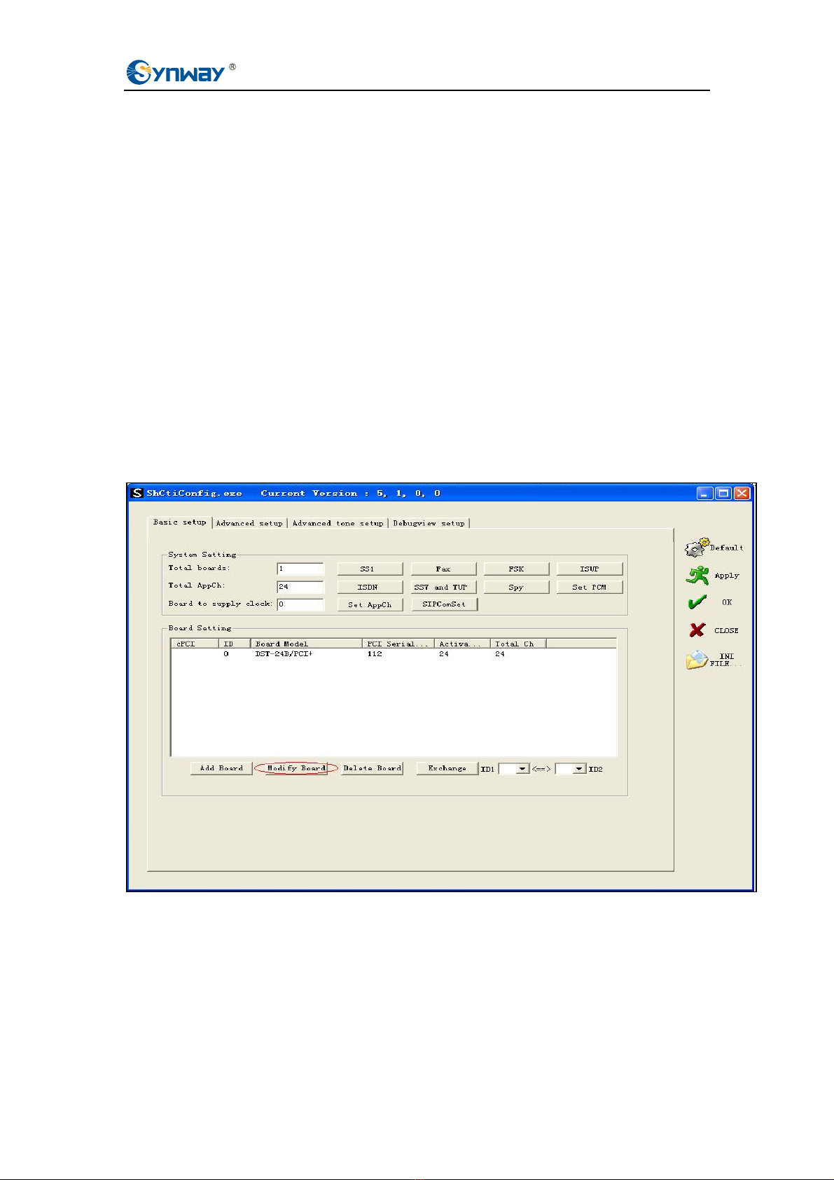
ShCtiConfig is a tool that enables the visualized setting of the system configuration file
ShConfig.ini, which is mandatory to Synway voice boards.
During the SynCTI driver installation, a voice board is configured as original default factory
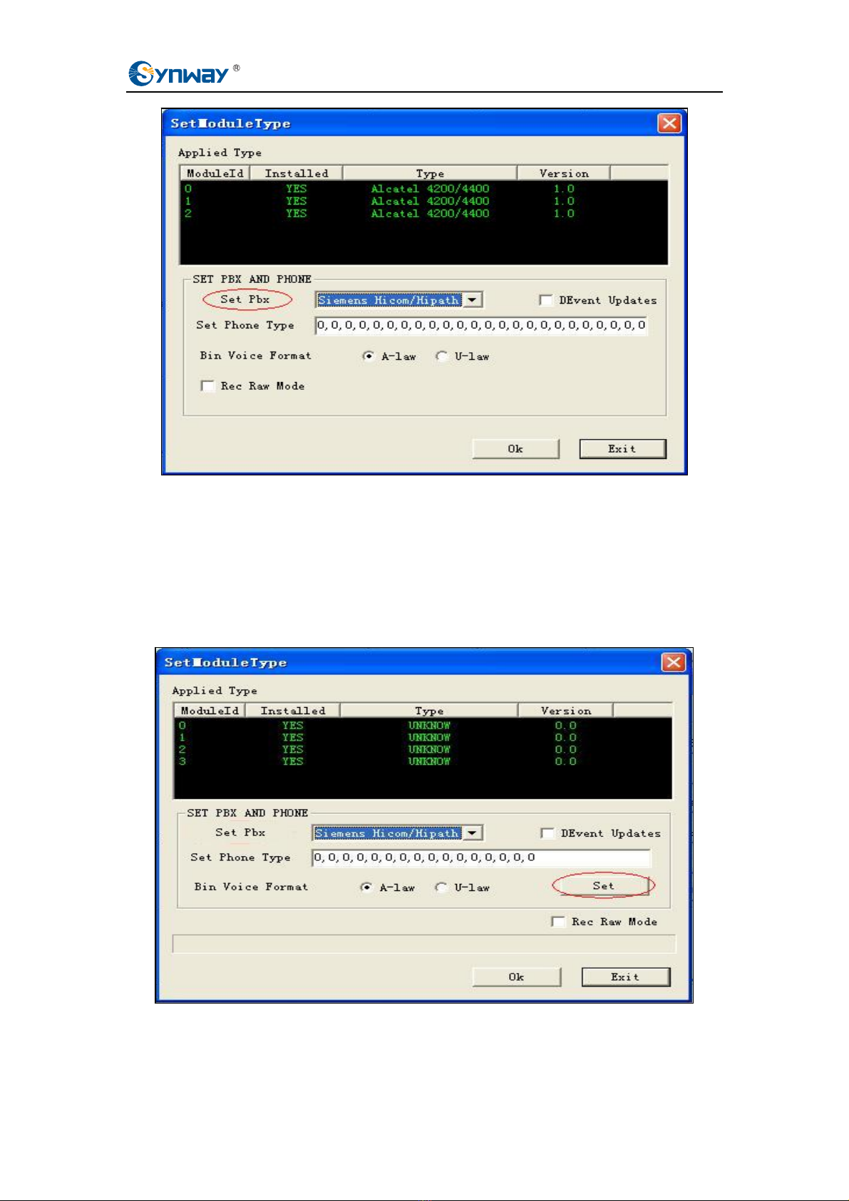
setting. For a digital station tap board, the two parameters PBXType and ModuleType are
by default set to Alcatel. In a practical use, if it is a DST A-type board that you install, you
must reconfigure such parameters according to actually monitored PBX and phone
models; if it is a DST B-type board that you install, you just modifies relative
configurations according to actually monitored PBX and phone models.
The DST series A-type board models include SHR-16DA-CT/PCI and SHR-24DA-CT/PCI,
while B-type board models include DST-24B/PCI, DST-24B/PCI+, DST-24B/PCIe and
DST-24B/PCIe+.
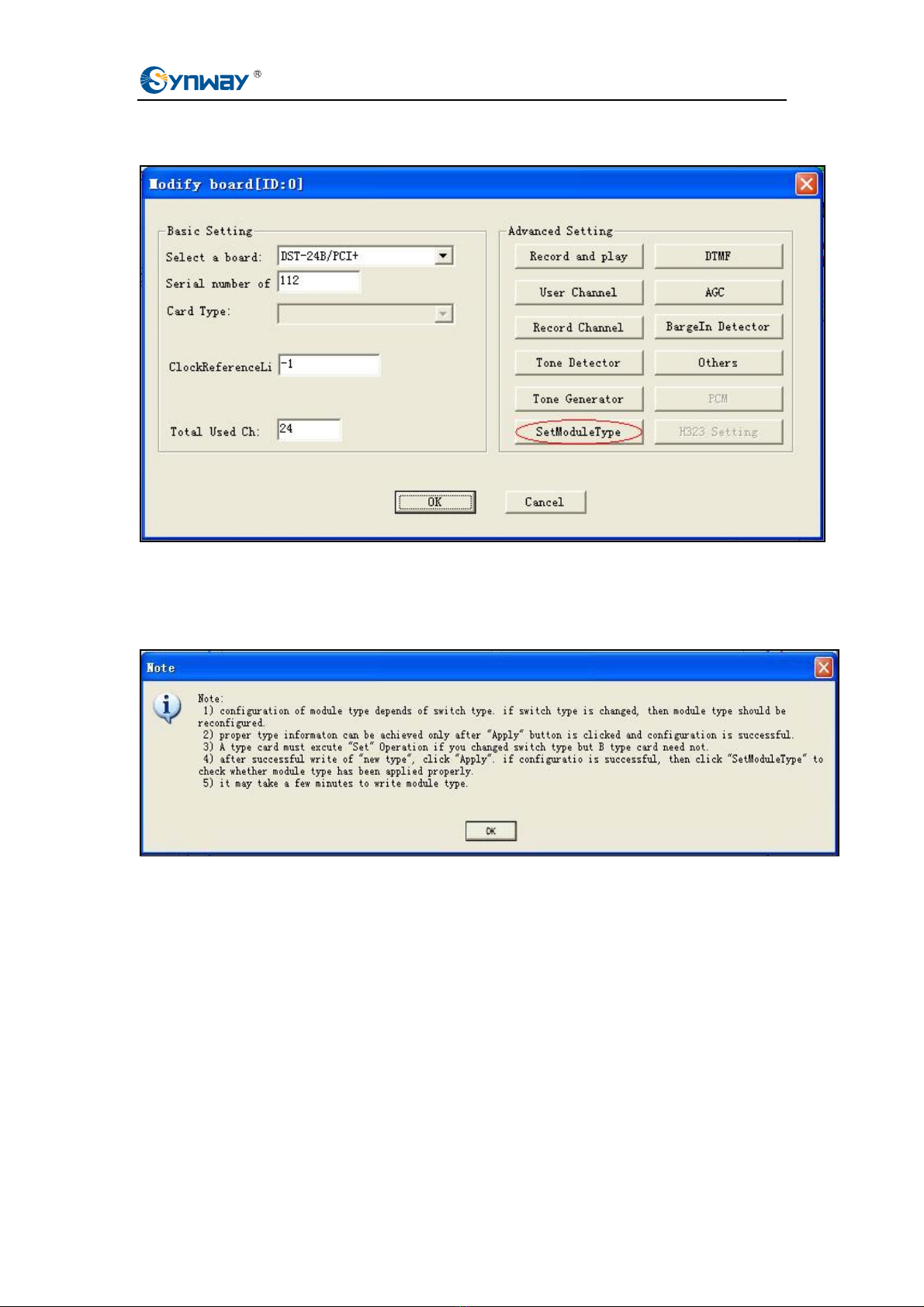
Only with a correct configuration performed by a specific software tool can the A-type
digital station tap board work properly. Once the driver is upgraded or the related vme file
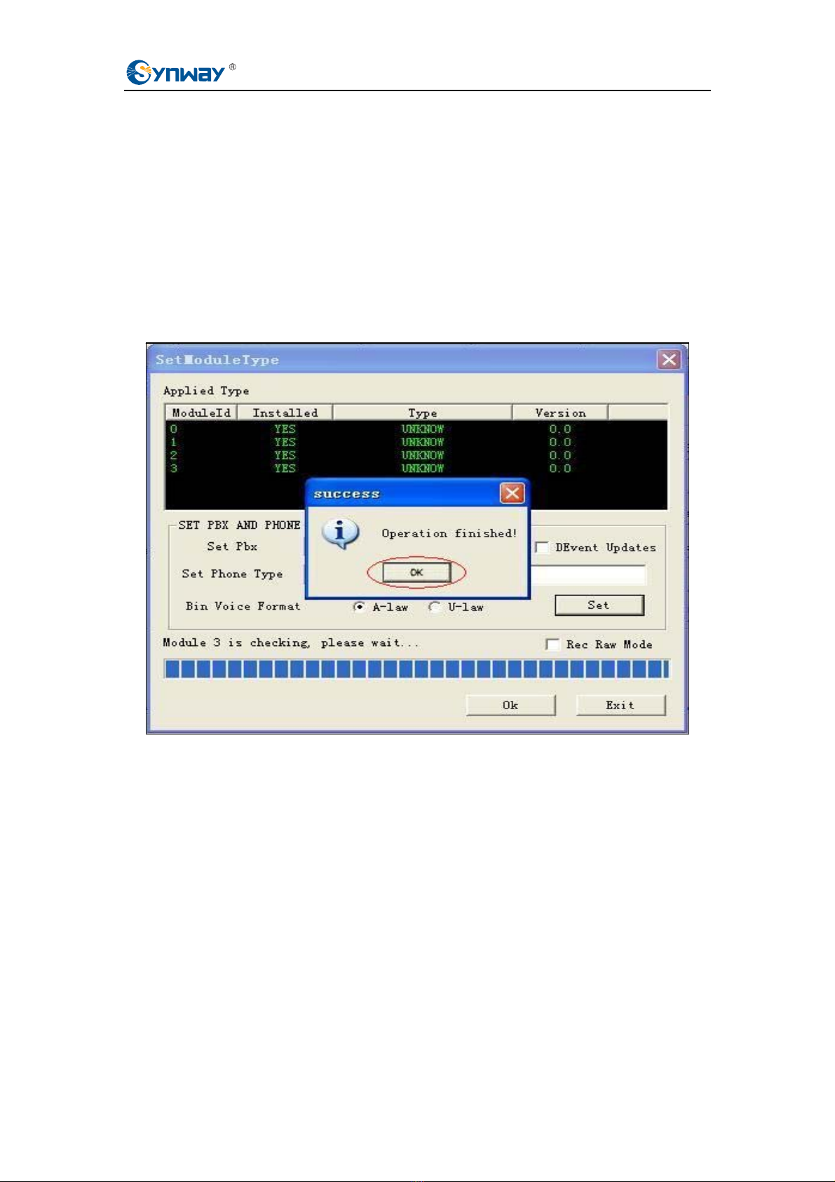
is modified, ModuleType must be reset via ShCtiConfig.exe. Note: The backup
configuration file ShConfig.ini is not allowed to copy to the current application directory
before the reset of ModuleType; otherwise, the digital station tap board will use the old
vme file instead of the new one.
For B-type digital station tap board, you can set PBX and phone models either by
modifying the configuration file ShConfig.ini directly or by using ShCtiConfig.exe. And the
system will automatically load the PBX and phone model that you configure. When the
driver is upgraded, you may use the backup configuration file ShConfig.ini.
The DST series boards have two working modes: Common Working Mode and Raw
Data Acquisition Mode. Only in Common Working Mode can the call recording system
work normally. Raw Data Acquisition Mode is a mode used in debugging to acquire raw
waveforms (to B-type boards) or raw code streams (to A-type boards) on the line for
analysis or troubleshooting .
Before configuring a digital station tap board, you should get the following information:
¾The manufacturer and model of your monitored PBXes
¾The specific model of the used digital phones
Digital Station Tap Board Configuration Manual Page iii

Synway Information Engineering Co., Ltd
Chapter 1 Start ShCtiConfig.exe
During initialization, ShCtiConfig.exe will check whether there is the system configuration
file ShConfig.ini under the current directory. If there is, the program will read and use the
configuration information in the file; otherwise, it will use the default settings for
configuration and then create the file ShConfig.ini under the current directory.
To ensure the use of those modified configuration items, the configuration file shconfig.ini
loaded by the application must be the correct one.
Digital Station Tap Board Configuration Manual Page 1

Synway Information Engineering Co., Ltd
Chapter 2 Configure DST Board
(Common Working Mode)
Please follow the procedures below to configure the digital station tap board to run in
Common Working Mode.
Step 1 : After a digital station tap board and its driver are installed properly, locate
ShCtiConfig.exe in c:/scti provided the installation path is set to c:/shcti, and run
it.
Then click the button ‘Default’. The basic information of the board installed will
be displayed in the list, including ID, Board Model, PCI Serial Number, etc. as
shown in the figure below.
Select the board model in the list and click the button ‘Modify Board’ to enter the
‘Modify board’ dialog box.
Figure 2-1
Digital Station Tap Board Configuration Manual Page 2

Synway Information Engineering Co., Ltd
Step 2 : In the dialog ‘Modify board’, click the button ‘SetModuleType’ as shown in Figure
2-2.
Figure 2-2
Step 3 : Now there pops up the dialog ‘Note’ as shown in Figure 2-3. Click the button
‘OK’ to enter the dialog box ‘SetMooduleType’.
Figure 2-3
Digital Station Tap Board Configuration Manual Page 3

Synway Information Engineering Co., Ltd
Step 4 : In the dialog ‘SetModuleType’, all module information is displayed in the list:
ModuleId----the number of the installed module;
Installed----indicates the module state;
(with two values: YES---means the module is installed; NO---means no module is installed);
Type---- the module type;
Version----the module version.
Select a module in the list and choose the PBX model that you use in the
options menu ‘Set Pbx’. (At present the Synway DST series boards have
supported such mainstream PBX series as ALCATEL, SIMENS and MERIDIAN.
For details about our supported PBX models, refer to the file
DST_PBX_Support.xls) The operation interface for DST A-type boards has a
button ‘set’ on it, as shown in Figure 2-4 below, while that for B-type boards
doesn’t have such button, as shown in Figure 2-5 below.
Figure 2-4 For A-type Boards
Digital Station Tap Board Configuration Manual Page 4

Synway Information Engineering Co., Ltd
Figure 2-5 For B-type Boards
Regarding how to deal with those PBX models not mentioned in this file, another
document ‘FAQ for Use of DST Board’ provides some useful suggestions.
Step 5 : After that, click the button ‘Set’ to evaluate the module type with the PBX model
that you chose. If necessary, set other modules displayed in the list in the same
way.
Figure 2-6 For A-type Boards
Note:
¾For DST B-type boards, this step can be skipped. Go directly to Step 7;
Digital Station Tap Board Configuration Manual Page 5

Synway Information Engineering Co., Ltd
¾For DSTA-type boards, this step cannot be skipped for the first time installation;
¾If the PBX model is not changed with the driver upgrade, the old configuration file still
can be used; however, the vme file must be updated for the monitoring module.
Otherwise, there may appear such problems as instability in operation and
abnormality in monitoring;
¾If the PBX model is changed with the driver upgrade, the vme file must be updated for
the monitoring module to comply with the new PBX model;
¾This step perhaps takes a few minutes.
Step 6 : Once a module setting is done, the dialog ‘success’ pops up. Click the button
‘OK’ as shown in Figure 2-7.
Figure 2-7 For A-type Boards
Step 7 : Go back to the dialog ‘SetModuleType’ and set the item ‘Set Phone Type’
according to your actually used phone model (refer to the file
DST_PBX_Support.xls for details) as shown in Figure 2-8 and Figure 2-9..
Digital Station Tap Board Configuration Manual Page 6

Synway Information Engineering Co., Ltd
Figure 2-8 For A-type Boards
Figure 2-9 For B-type Boards
For those phone models unmentioned in that section, you can try the value 0, 1 or 2. For
more information, refer to the document ‘FAQ for Use of DST Board’.
The voice data format supported by the .bin file means the supported encoding format on
the line. A wrong configuration may probably cause noises in recorded voices, so it is
necessary to confirm the line encoding format with the PBX at the other end upon
Digital Station Tap Board Configuration Manual Page 7

Synway Information Engineering Co., Ltd
configuration. Generally there is no problem using the default configuration. In case the
recorded voice has a lot of noises in it or sounds quite indistinct, you can modify the
configuration item to reset the voice data format supported by the .bin file. If the problem is
still not solved, refer to the document ‘FAQ for Use of DST Board’.
Step 8 : After setting the phone model, click the button ‘Ok’ to exit the dialog
‘SetModuleType’ as shown in Figure 2-10 and Figure 2-11.
Figure 2-10 For A-type Boards
Figure 2-11 For B-type Boards
Step 9 : Then click the button ‘OK’ to exit the dialog ‘Modify board’ as shown in Figure
Digital Station Tap Board Configuration Manual Page 8

Synway Information Engineering Co., Ltd
2-12.
Figure 2-12
Step 10 :Finally click on ‘Apply’ to apply the settings made above and the message
‘Current configuration succeeds’ will pop up as shown in Figure 2-13 if all
settings are done properly.
Figure 2-13
Note:
¾The module information displayed on the interface will not be updated.until you press
the button ‘Apply’ and see the dialog saying ‘Current configuration succeeds’. That is,
only when you go back to ‘SetModuleType’ again after passing the verification could
Digital Station Tap Board Configuration Manual Page 9

Synway Information Engineering Co., Ltd
you find the module type as configured shown on the interface. Refer to Figure 2-14
and Figure 2-15 below.
Figure 2-14 For A-type Boards
Figure 2-15 For B-type Boards
¾To check if the module type has been successfully updated, click the button ‘Apply’
after your setting to see the current information.
Digital Station Tap Board Configuration Manual Page 10

Synway Information Engineering Co., Ltd
Chapter 3 Configure DST Board (Raw
Data Acquisition Mode)
Please follow the procedures below to configure the digital station tap board to run in Raw
Data Acquisition Mode.
Step 1 : After a digital station tap board and its driver are installed properly, locate
ShCtiConfig.exe in c:/scti provided the installation path is set to c:/shcti, and run
it.
Then click the button ‘Default’. The basic information of the board installed will
be displayed in the list, including ID, Board Model, PCI Serial Number, etc. as
shown in the figure below.
Select the board model in the list and click the button ‘Modify Board’ to enter the
‘Modify board’ dialog box.
Figure 3-1
Digital Station Tap Board Configuration Manual Page 11

Synway Information Engineering Co., Ltd
Step 2 : In the dialog ‘Modify board’, click the button ‘SetModuleType’ as shown in Figure
3-2.
Figure 3-2
Step 3 : Now there pops up the dialog ‘Note’ as shown in Figure 3-3. Click the button
‘OK’ to enter the dialog box ‘SetMooduleType’.
Figure 3-3
Digital Station Tap Board Configuration Manual Page 12

Synway Information Engineering Co., Ltd
Step 4 : Tick the option ‘Rec Raw Mode’ in the dialog ‘SetModuleType’ and do not
change any other configurations. Note that, to A-type boards, you still need to
use the button ‘set’ for configuration. See Figure 3-4 and Figure 3-5 below.
Figure 3-4 For A-type Boards
Figure 3-5 For B-type Boards
Step 5 : Click the button ‘Set’ in Figure 3-4 above.
Digital Station Tap Board Configuration Manual Page 13

Synway Information Engineering Co., Ltd
Figure 3-6 For A-type Boards
Note:
For DST B-type boards, this step can be skipped. Go directly to Step 7.
Step 6 : Once a module setting is done, the dialog ‘success’ pops up. Click the button
‘OK’ as shown in Figure 3-7.
Figure 3-7 For A-type Boards
Step 7 : Click the button ‘Ok’ to exit the dialog ‘SetModuleType’ as shown in Figure 3-8
Digital Station Tap Board Configuration Manual Page 14

Synway Information Engineering Co., Ltd
and Figure 3-9.
Figure 3-8 For A-type Boards
Figure 3-9 For B-type Boards
Digital Station Tap Board Configuration Manual Page 15

Synway Information Engineering Co., Ltd
Step 8 : Then click the button ‘OK’ to exit the dialog ‘Modify board’ as shown in Figure
3-10.
Figure 3-10
Step 9 : Finally click on ‘Apply’ to apply the settings made above and the message
‘Current configuration succeeds’ will pop up as shown in Figure 3-11 if all
settings are done properly.
Figure 3-11
Digital Station Tap Board Configuration Manual Page 16
Other manuals for DST Series
1
This manual suits for next models
2
Table of contents
Other Synway Motherboard manuals