Synway SSW020A User manual

Synway UMCT Series
SSW020 Series
SSW030 Series
SSW080 Series
UMCT Intelligent Switch
Version 1.3
Synway Information Engineering Co., Ltd
www.synway.net

Synway Information Engineering Co., Ltd
UMCT Intelligent Switch Hardware Manual (Ver. 1.3) Page i
Contents
Contents..................................................................................................................................................i
Copyright Declaration...........................................................................................................................ii
Revision History...................................................................................................................................iii
Chapter 1 Overview......................................................................................................................1
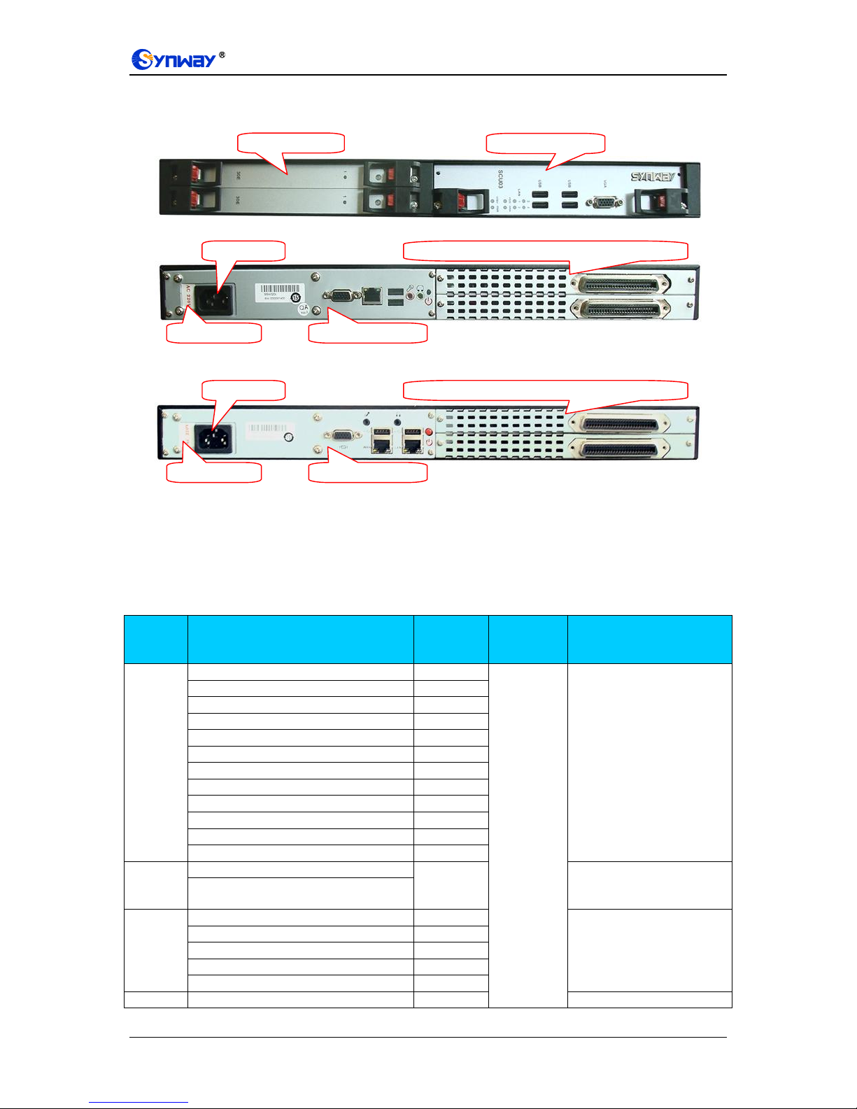
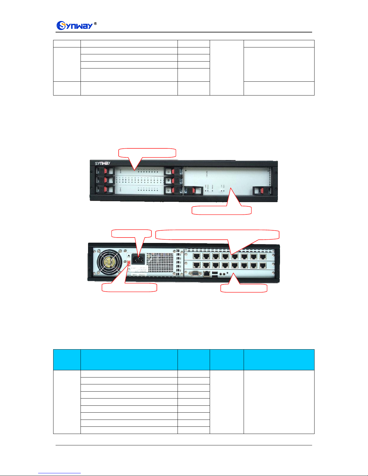
1.1 SSW020A/SSW020A(2.0) .......................................................................................................1
1.2 SSW030A ................................................................................................................................3
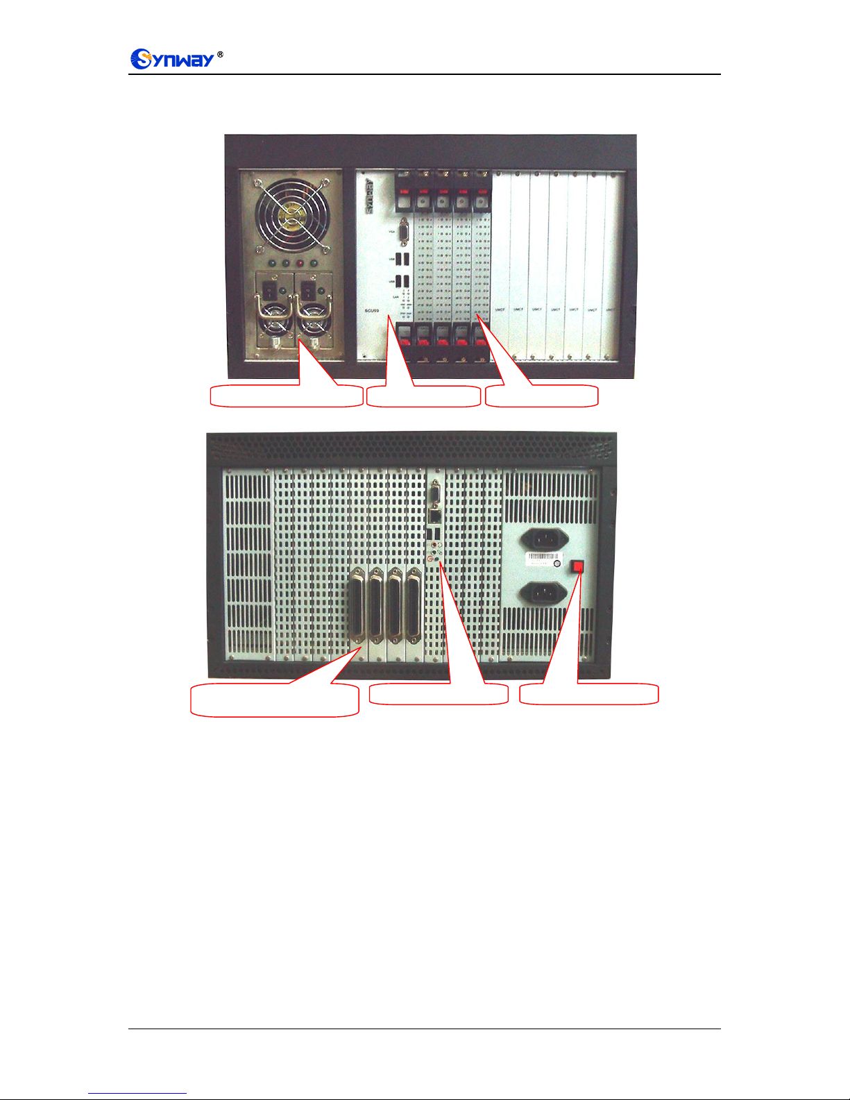
1.3 SSW080A/SSW080B/SSW080C.............................................................................................4
Chapter 2 Installation...................................................................................................................8
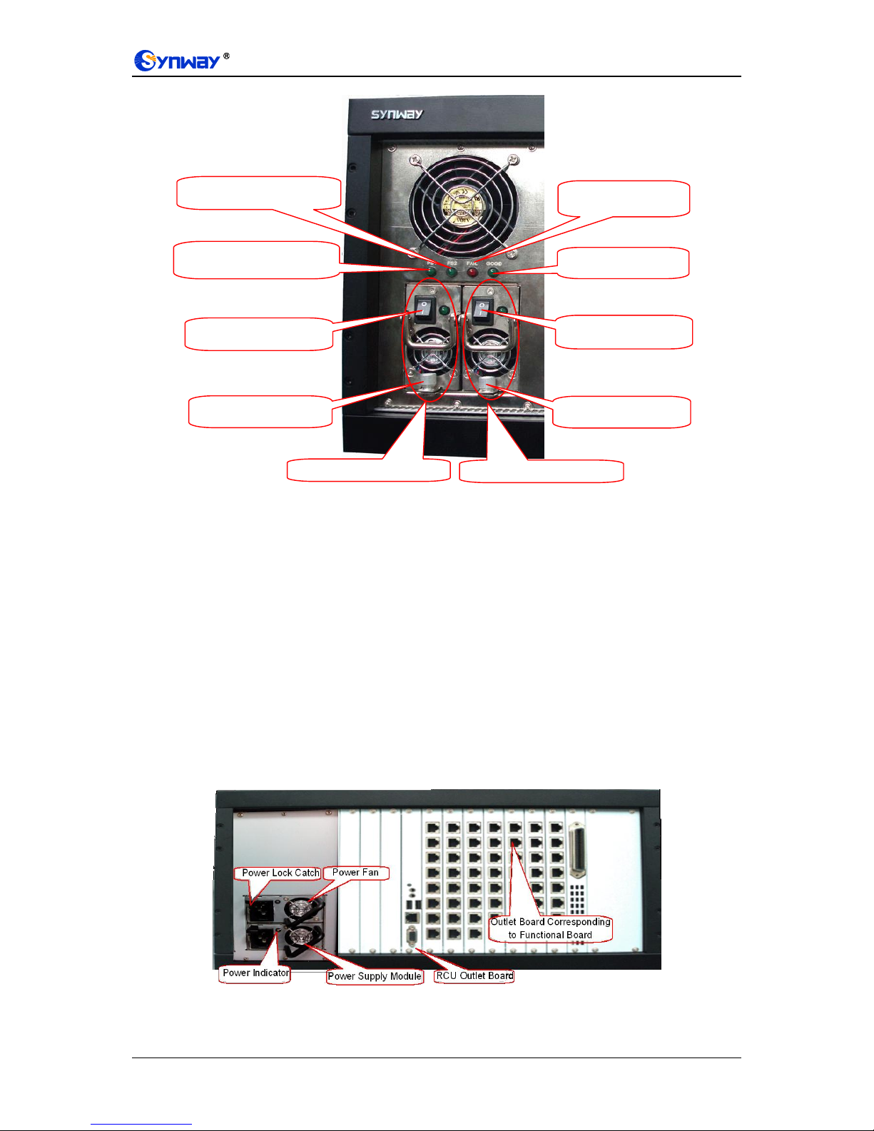
2.1 Hardware Installation...............................................................................................................8
2.2 Turnon/Turnoff........................................................................................................................10
2.2.1 Turn-on Operation..............................................................................................................10
2.2.2 Turn-off Operation..............................................................................................................11
2.3 Hot Replacement...................................................................................................................11
2.4 Fan Changing ........................................................................................................................11
2.4.1 Fans in 2U Chassis............................................................................................................12
2.4.2 Fans in 6U Chassis............................................................................................................12
Appendix A Technical Specifications...............................................................................................14
Appendix B Troubleshooting.............................................................................................................17
Appendix C Technical/sales Support................................................................................................18

Synway Information Engineering Co., Ltd
UMCT Intelligent Switch Hardware Manual (Ver. 1.3) Page ii
Copyright Declaration
All rights reserved; no part of this document may be reproduced or transmitted in any form or by
any means, electronic or mechanical, without prior written permission from Synway Information
Engineering Co., Ltd (hereinafter referred to as ‘Synway’).
Synway reserves all rights to modify this document without prior notice. Please contact Synway for
the latest version of this document before placing an order.
Synway has made every effort to ensure the accuracy of this document but does not guarantee
the absence of errors.

Synway Information Engineering Co., Ltd
UMCT Intelligent Switch Hardware Manual (Ver. 1.3) Page iii
Revision History
Version
Date
Comments
Version 1.0
2009-12
Initial publication
Version 1.1
2010-7
Add description on the new UMCT intelligent switch
model SSW020A.
Version 1.2
2013-7
Add description on the new UMCT intelligent switch
model SSW020A(2.0). Update some board information
and relative contents.
Version 1.3
2014-12
Add description on the new UMCT intelligent switch
model SSW080C.
Note: Please visit our website http://www.synway.net to obtain the latest version of this document.

Synway Information Engineering Co., Ltd
UMCT Intelligent Switch Hardware Manual (Ver. 1.3) Page 1
Chapter 1Overview
The Synway UMCT intelligent switch adopts the X86 industrial embedded platform which has the
Com Express structure as the main control unit. It owns all essential features of a PBX, such as
the excellent expansibility and the capability to support a variety of functional boards. What’s more,
it supports all applications of the SynCTI driver platform as well as open source software like
Asterisk.
The UMCT intelligent switch is extendable and allows hot swap of boards (replacing boards while
the computer system using them remains in operation). The overall design features high
efficiency and good ventilation. Especially, the SSW080B intelligent switch adopts the
redundancy design, further ensuring the reliability in operation.
The UMCT intelligent switch models and their supported boards are shown in the table below (★
denotes supported).
UMCT Model
SCU Series
Board Series
RCU Series
SCU03
SCU03-
3
SCU06(2.0)
SCU07
SCU08
SHD
SHT
SHN
DST
TEJ
FXM
Max.
Inserte
d
Boards
RCU01
RCU02
RCU04
SSW020
★
★
★
★
★
★
★
2
★
★
SSW020(2.0)
★
★
★
★
★
★
★
3
★
★
SSW030A
★
★
★
★
★
★
★
★
★
★
3
★
★
SSW080A
★
★
★
★
★
★
★
★
★
★
8
★
★
★
SSW080B
★
★
★
★
★
★
★
★
★
★
8
★
★
★
SSW080C
★
★
★
★
★
★
★
★
★
★
8
★
★
★
SSW080C(DC)
★
★
★
★
★
★
★
★
★
★
8
★
★
★
Note: A single switch can accommodate only a piece of SCU as well as a piece of RCU, but multiple voice boards
in different series.
Table 1-1 List of Board Models Supported by UMCT Intelligent Switch
Feature
Series
Note
Digital trunk board
SHD
Provides E1/T1 digital line interface
Analog voice board
SHT
Provides analog line interface
VoIP board
SHN
Provides VoIP interface
Digital station tap board
DST
Provides high-impedance recording of
digital phone lines
AST series digital board
TEJ
Supports digital voice interface of Asterisk
platform
AST series analog board
FXM
Supports analog voice interface of Asterisk
platform
Table 1-2 List of Board Types and Feature Description
1.1 SSW020A/SSW020A(2.0)
The SSW020A and SSW020A(2.0) UMCT intelligent switches are 1U in height and support up to
2 UMCT series voice boards.
The SSW020A is equipped with an RCU01 outlet board which accommodates the following
interfaces: a VGA, a network interface, two USB2.0, two sound card interfaces and a Power key.
See Figure 1-1 and Figure 1-2 for its hardware structure.
The SSW020A(2.0) is equipped with an RCU05 outlet board which accommodates the following

Synway Information Engineering Co., Ltd
UMCT Intelligent Switch Hardware Manual (Ver. 1.3) Page 2
interfaces: a VGA, two network interfaces, two USB2.0, two sound card interfaces and a Power
key. See Figure 1-1 and Figure 1-3 for its hardware structure.
Figure 1-1 SSW020A/ SSW020A(2.0) Front Panel
Figure 1-2 SSW020A Rear Panel
Figure 1-3 SSW020A(2.0) Rear Panel
The SSW020A and SSW020A(2.0) switches support two options for power supply: 220V AC and
110V AC, which can be selected by the voltage switch.
Note: Make sure the voltage option you choose conform to the actual voltage input before you
power on the machine.
See Table 1-3 for the board models supported by SSW020A/SSW020A(2.0).
Series
Board Model
Available
Ports per
Board
Max.
Inserted
Boards
Note
SHD
SHD-30E-CT/PCI(SSW)
30
2
Up to 16 E1 digital
interfaces configurable
per system, with the
maximum capacity of
480 ports
Up to 128 fax channels
available per system
SHD-30E-CT/PCI/EC(SSW)
30
SHD-60E-CT/PCI(SSW)
60
SHD-60E-CT/PCI/EC(SSW)
60
SHD-120E-CT/PCI(SSW)
120
SHD-120E-CT/PCI/EC(SSW)
120
SHD-240E-CT/PCI(SSW)
240
SHD-240E-CT/PCI/EC(SSW)
240
SHD-30E-CT/PCI/FAX(SSW)
30
SHD-60E-CT/PCI/FAX(SSW)
60
SHD-120E-CT/PCI/FAX(SSW)
120
SHD-240E-CT/PCI/FAX (SSW)
240
SHT
SHT-16C-CT/PCI/EC(SSW)
16
Up to 32 analog trunk
channels configurable
per system
SHT-16C-CT/PCI/FAX(SSW)
SHN
SHN-8B-CT/PCI+(SSW)
8
Up to 240 VoIP
channels available per
system
SHN-16B-CT/PCI+(SSW)
16
SHN-32B-CT/PCI+(SSW)
32
SHN-60B-CT/PCI+(SSW)
60
SHN-120B-CT/PCI+(SSW)
120
DST
DST-24B/PCI(SSW)
24
Up to 48 channels
Power Socket
Outlet Board Corresponding to Functional Board
Voltage Switch
RCU05 Outlet Board
Power Socket
Outlet Board Corresponding to Functional Board
Voltage Switch
RCU01 Outlet Board
Functional Boards
Switch Control Unit

Synway Information Engineering Co., Ltd
UMCT Intelligent Switch Hardware Manual (Ver. 1.3) Page 3
available per system
TEJ
TEJ101P(SSW)
30
Up to 16 E1 digital
interfaces configurable
per system, with the
maximum capacity of
480 ports
TEJ201P(SSW)
60
TEJ401P(SSW)
120
TEJ801P(SSW)
240
FXM
FXM3201P(SSW)
32
Up to 64 voice channels
available per system
Table 1-3 Model List of Functional Boards
1.2 SSW030A
The SSW030A UMCT intelligent switch is 2U in height and supports up to 3 UMCT series voice
boards. See Figure 1-4 and Figure 1-5 for its hardware structure.
Figure 1-4 SSW030A Front Panel
Figure 1-5 SSW030A Rear Panel
The SSW030A switch supports two options for power supply: 220V AC and 110V AC, which can
be selected by the voltage switch.
Note: Make sure the voltage option you choose conform to the actual voltage input before you
power on the machine.
See Table 1-4 for the board models supported by SSW030A.
Series
Board Model
Available
Ports per
Board
Max.
Inserted
Boards
Note
SHD
SHD-30E-CT/PCI(SSW)
30
3
Up to 24 E1 digital
interfaces configurable
per system, with the
maximum capacity of
720 ports
Up to 192 fax channels
available per system
SHD-30E-CT/PCI/EC(SSW)
30
SHD-60E-CT/PCI(SSW)
60
SHD-60E-CT/PCI/EC(SSW)
60
SHD-120E-CT/PCI(SSW)
120
SHD-120E-CT/PCI/EC(SSW)
120
SHD-240E-CT/PCI(SSW)
240
SHD-240E-CT/PCI/EC(SSW)
240
SHD-30E-CT/PCI/FAX(SSW)
30
Power Socket
Outlet Board Corresponding to Functional Board
RCU Outlet Board
Voltage Switch
Functional Boards
Switch Control Unit

Synway Information Engineering Co., Ltd
UMCT Intelligent Switch Hardware Manual (Ver. 1.3) Page 4
SHD-60E-CT/PCI/FAX(SSW)
60
SHD-120E-CT/PCI/FAX(SSW)
120
SHD-240E-CT/PCI/FAX (SSW)
240
SHT
SHT-16C-CT/PCI/EC(SSW)
16
Up to 48 analog trunk
channels configurable
per system
SHT-16C-CT/PCI/FAX(SSW)
SHN
SHN-8B-CT/PCI+(SSW)
8
Up to 360 VoIP
channels available per
system
SHN-16B-CT/PCI+(SSW)
16
SHN-32B-CT/PCI+(SSW)
32
SHN-60B-CT/PCI+(SSW)
60
SHN-120B-CT/PCI+(SSW)
120
DST
DST-24B/PCI(SSW)
24
Up to 72 channels
available per system
TEJ
TEJ101P(SSW)
30
Up to 24 E1 digital
interfaces configurable
per system, with the
maximum capacity of
720 ports
TEJ201P(SSW)
60
TEJ401P(SSW)
120
TEJ801P(SSW)
240
FXM
FXM3201P(SSW)
32
2
Up to 64 voice channels
available per system
Table 1-4 Model List of Functional Boards
1.3 SSW080A/SSW080B/SSW080C
The SSW080A, SSW080B and SSW080C UMCT intelligent switches are 6U in height and
support up to 8 UMCT series voice boards.
The SSW080A switch adopts common power supply. See Figure 1-6 for its hardware structure.
The SSW080A switch supports two options for power supply: 220V AC and 110V AC, which can
be selected by the voltage switch.
Note: Make sure the voltage option you choose conform to the actual voltage input before you
power on the machine.
Figure 1-6 SSW080A Front Panel
The difference between SSW080B and SSW080A is that the SSW080B switch has a redundant
power supply which further guarantees the operating stability. See Figure 1-7 and Figure 1-8 for
the hardware structure of SSW080B.
Switch Control Unit
Baffle
Functional Board

Synway Information Engineering Co., Ltd
UMCT Intelligent Switch Hardware Manual (Ver. 1.3) Page 5
The SSW080B supports a wide range of AC input, i.e. 100V~240V, 47~63Hz and the maximum
current of 4A.
Figure 1-7 SSW080B Front Panel
Figure 1-8 SSW080B Rear Panel
Note: Apart from the redundant power supply, the rear panel of SSW080A is the same as that of
SSW080B.
Outlet Board Corresponding
to Functional Board
BUZZER RESET Button
RCU Outlet Board
Switch Control Unit
Redundant Power Supply
Functional Board

Synway Information Engineering Co., Ltd
UMCT Intelligent Switch Hardware Manual (Ver. 1.3) Page 6
Figure 1-9 Redundant Power Supply
In the above Figure 1-9, the two screws are used respectively to fix the two redundant power
supplies to prevent loose in running.
If both power supply modules work normally, the indicator marked Good lights up while the
indicator marked Fall goes out; if either of these two power supplies becomes invalid, the Good
indicator goes out and the Fall indicator lights up, meanwhile the corresponding PS1 or PS2 goes
out and an alarm goes off. To stop the alarm, press the BUZZER RESET button on the rear panel
as shown in Figure 1-8.
SSW080C supports both AC power and +48V DC power, where lies the difference from
SSW080B. What’s more, AC and DC power modules are allowed to work together to further
guarantee the operating stability. The front panel of SSW080C is the same as that of SSW080A.
See Figure 1-10 for the rear panel of SSW080C.
SSW080C supports a wide range of AC input, i.e. 100V~240V, 47~63Hz, with the maximum
current of 6A. And the DC input range it supports is 42-60V DC.
Figure 1-10 SSW080C Rear Panel
Redundant power supply 1
Redundant power supply 2
PS1 (Indicator for redundant
power supply module 1)
PS2 (Indicator for redundant
power supply module 2)
FALL (Power supply
failure indicator)
GOOD (Power supply
normal indicator)
Switch of redundant
power supply module 1
Switch of redundant
power supply module 2
Screw for redundant
power supply module 1
Screw for redundant
power supply module 2

Synway Information Engineering Co., Ltd
UMCT Intelligent Switch Hardware Manual (Ver. 1.3) Page 7
If the power supply module works normally, the indicator lights up green; if it goes abnormal, the
indicator lights up orange and an alarm buzzes. To stop the alarm, pull out the abnormal power
supply module.
The method to insert or extract the power supply:
To insert the power supply module, push it home into the slot until it can go no further. To extract
the power supply module, open the power lock catch by pulling it toward the power fan and draw
the power supply module until it is completely out.
SSW080C supports the 5”hard disk, but it requires SCU08 or above.
The method to install the HD:
a) Disassemble the two vacant panels beside the RCU outlet board, and take out the HD
installation bracket.
b) Use the HD shock pad and screws to fix the hard disk onto the HD installation bracket.
c) Connect the flat cable properly for the HD.
d) Plug back the HD installation bracket and reinstall the two vacant panels. Now the HD
installation finishes.
See Table 1-5 for the board models supported by SSW080A/SSW080B/SSW080C.
Series
Board Model
Available
Ports per
Board
Max.
Inserted
Boards
Note
SHD
SHD-30E-CT/PCI(SSW)
30
8
Up to 64 E1 digital
interfaces configurable
per system, with the
maximum capacity of
1920 ports
Up to 512 fax channels
available per system
SHD-30E-CT/PCI/EC(SSW)
30
SHD-60E-CT/PCI(SSW)
60
SHD-60E-CT/PCI/EC(SSW)
60
SHD-120E-CT/PCI(SSW)
120
SHD-120E-CT/PCI/EC(SSW)
120
SHD-240E-CT/PCI(SSW)
240
SHD-240E-CT/PCI/EC(SSW)
240
SHD-30E-CT/PCI/FAX(SSW)
30
SHD-60E-CT/PCI/FAX(SSW)
60
SHD-120E-CT/PCI/FAX(SSW)
120
SHD-240E-CT/PCI/FAX (SSW)
240
SHT
SHT-16C-CT/PCI/EC(SSW)
16
Up to 128 analog trunk
channels configurable
per system
SHT-16C-CT/PCI/FAX(SSW)
SHN
SHN-8B-CT/PCI+(SSW)
8
Up to 960 VoIP
channels available per
system
SHN-16B-CT/PCI+(SSW)
16
SHN-32B-CT/PCI+(SSW)
32
SHN-60B-CT/PCI+(SSW)
60
SHN-120B-CT/PCI+(SSW)
120
DST
DST-24B/PCI(SSW)
24
Up to 192 channels
available per system
TEJ
TEJ101P(SSW)
30
Up to 64 E1 digital
interfaces configurable
per system, with the
maximum capacity of
1920 ports
TEJ201P(SSW)
60
TEJ401P(SSW)
120
TEJ801P(SSW)
240
FXM
FXM3201P(SSW)
32
Up to 256 voice
channels per system,
inclusive of 96 station
channels at most for
SSW080A/B and 256
station channels at most
for SSW080C.
Table 1-5 Model List of Functional Boards

Synway Information Engineering Co., Ltd
UMCT Intelligent Switch Hardware Manual (Ver. 1.3) Page 8
Chapter 2 Installation
2.1 Hardware Installation
Note: SSW020A, SSW020A(2.0), SSW030A, SSW080A, SSW080B and SSW080C are
approximately the same in hardware architecture. Here we take the SSW030A switch for
example to demonstrate the installation procedures.
Step1: Check if the packed board and modules are in good condition.
When taking apart the package, you will see a board as shown in Figure 2-1, Figure 2-2 below.
Figure 2-1 Front Panel
Figure 2-2 Rear Panel
Note: The SCU (switch control unit) is allowed to be pulled out. To do so, first loosen off
the screws on the panel and press both red buttons on the board handle at the same time.
Wait until the board breaks away from the locking hole on the chassis and draw it
horizontally out.
Note: Pulling out the SCU during system runtime may result in such problems as system
shut down or data missing. Therefore, don’t forget to close the system before taking out
the SCU.
Step2: Install the functional boards
Note: For the board models supported by the UMCT intelligent switch, refer to Table 1-2
and Table 1-4. All of them are composed of two parts: the mainboard and the outlet board.
It doesn’t matter to insert the mainboard first or insert the outlet board first. Just make
sure to insert the mainboard and the corresponding outlet board to a right pair of vacant
slots on the front and back panels of the chassis.
Remove the baffle for functional board as shown in Figure 2-1 before installing the functional
board. Then you will see guide rails on both sides and slots inside on the functional board. See
Figure 2-3 below.
Switch Control Unit
Baffle for Functional Board
Power Socket
RCU Outlet Board
Baffle for Outlet Board

Synway Information Engineering Co., Ltd
UMCT Intelligent Switch Hardware Manual (Ver. 1.3) Page 9
Figure 2-3 Guide Rails for Functional Boards
Figure 2-4 Board Insertion
Smoothly insert the functional board to the guide rails as shown in Figure 2-4. With the board
completely inserted, push the upper and bottom handles inwards at the same time until a ‘click’
sound is heard. The board is now properly fitted.
Note: The board can be further fastened with screws on the handle for extended use and
prevention of accidental removal. See Figure 2-4 above.
To pull the board out, first loosen off the screws on the panel and press both red buttons on the
board handle at the same time. Wait until the board breaks away from the locking hole on the
chassis and draw it horizontally out.
Step3: Install the outlet board.
Remove the baffle for outlet board as shown in Figure 2-2 before installing the outlet board. Then
you will see guide rails on both sides and slots on the outlet board. See Figure 2-5 below.
Figure 2-5 Rear Panel
Smoothly insert the outlet board to the guide rails.
Guide Rail1
Guide Rail 2
Slot on Outlet Board
Guide Rails
On-board Slots
Screw here to fix the functional board

Synway Information Engineering Co., Ltd
UMCT Intelligent Switch Hardware Manual (Ver. 1.3) Page 10
Figure 2-6 Rear Panel
With the outlet board completely inserted, screw on the corresponding rear panel to fix it. Now the
outlet board is properly fitted.
Note: To pull out the outlet board, just loosen off the screws on the rear panel and take it
out by hand.
2.2 Turnon/Turnoff
2.2.1 Turn-on Operation
First of all, check if the power cord is connected properly, if the HD and the memory on the SCU is
intact, if all necessary boards are well installed, and if the display, the keyboard, the mouse are all
connected to right interfaces (see Figure 2-7).
Figure 2-7 Interfaces to Display, Mouse, Keyboard and Network
When the intelligent switch is connected to the power, the STDBY indicator on the SCU keeps on
all the time.
Figure 2-8 Indicators on SCU
LINK
HDD
ACT
STDBY
POWER
Ethernet
USB
VGA
POWER
AUD OUT
AUD IN

Synway Information Engineering Co., Ltd
UMCT Intelligent Switch Hardware Manual (Ver. 1.3) Page 11
Push the POWER button (see Figure 2-7) to start the switch. Then the STDBT indicator goes out
while the POWER indicator lights up and keeps on all the time. During computer startup, the HDD
indicator lights up and keeps winking. Meanwhile, there appears the normal boot screen on the
computer. Now the switch is started up successfully.
2.2.2 Turn-off Operation
Except for using the system turnoff command, you can keep pressing the POWER button to turn
off the switch. Once it is turned off, the POWER indicator goes out while the STDBY indicator
lights up and keeps on all the time. Only after the switch is disconnected from the power will the
STDBY indicator go out.
2.3 Hot Replacement
The UMCT intelligent switches support the feature of hot replacement which allows users to take
out and replace the damaged components or boards during system runtime so as to improve the
system capability of recovering from disasters as well as the system expansibility and flexibility. At
present they do not support the hot-add operation.
To perform hot replacement during system runtime, stop the running boards first and pull out the
one to be replaced. Insert the new board and start it in the system. This operation is now
completed.
Note: Directly pulling out boards with relative applications unclosed may result in data
loss or system malfunction.
The following operations are not supported so far.
1) Install a functional board after the system is started up.
2) During system runtime, pull out a functional board and install another one of new kind or
move a functional board from one slot to another and reinstall it.
Notes:
a) Push the board home into the slot until it can go no further, and ensure that it is
not inclined at an angle before applying lever action on the handles to secure it.
The contact may become loose or the on-board Hot-Swap indicator may turn to be
blue (the Hot-Swap indicator keeps off when the board is working smoothly), or
even the connecting parts on the mainboard of the switch may be damaged if:
(I) Handles are used too early
(II) Handles are used while the board is inclined
(III) Force on handles is not applied evenly.
b) A board can be inserted when the computer is powered on. However, as strong
static electricity may lead to damages, the operator should touch a grounded
conductor to discharge the static electricity on him before inserting the board.
2.4 Fan Changing
Note: Usually the switch we provide has been installed with a fan in the chassis. Only when
the fan is broken does it need to be changed.

Synway Information Engineering Co., Ltd
UMCT Intelligent Switch Hardware Manual (Ver. 1.3) Page 12
2.4.1 Fans in 2U Chassis
Figure 2-9 Fan Plate in 2U Chassis
Fans in a 2U chassis are shown in Figure 2-9 above. To change fans in a 2U chassis, follow the
steps below.
Step1: Take the SCU out from the chassis and you can see the fans in the switch as shown in
Figure 2-10.
Figure 2-10 Fans Location in 2U Chassis
Step2: Loosen off the screws shown in Figure 2-10 and draw out the damaged fan plate.
Note: The fan plate can not be taken out vertically. Please incline it a little bit to right and
then pull it out.
Step3: Insert a new fan plate to the corresponding slots on the chassis.
Step4: Tighten up the screws to fix the new fan plate.
2.4.2 Fans in 6U Chassis
Figure 2-11 Fan Plate in 6U Chassis
Fans in a 6U chassis are shown in Figure 2-11 above. To change fans in a 6U chassis, follow the
steps below.
Step1: Open the upper cover of a 6U chassis to see the fan plate.
Screw to fix fan plate
Fan

Synway Information Engineering Co., Ltd
UMCT Intelligent Switch Hardware Manual (Ver. 1.3) Page 13
Step2: Loosen off the screws that fix the fan plate and tear down the broken fans. Replace them
with new fans and tighten up the screw to fix the fan plate. See Figure 2-12 below.
Figure 2-12 Fans Location in 6U Chassis
Slot for Fan Plate
Screw to fix fan plate

Synway Information Engineering Co., Ltd
UMCT Intelligent Switch Hardware Manual (Ver. 1.3) Page 14
Appendix A Technical Specifications
SSW020A 1U Specifications
Safety
Lightning resistance: Level 4
Certification: FCC CE
Physical Size
Height: 44.2.mm (1U)
Width: 442mm (19″)
Depth: 362mm
Weight: 4~6kg
Power Requirements
AC: 220V/110V
Frequency: 50Hz/60Hz
Maximum power: 200W
Environment
Well ventilated
Relative humidity: 10%~85%
To prevent static: Ensure proper grounding
﹡Suggested temperature: 0℃~40℃
﹡Keep clean, get away from dust
﹡Standard 19”chassis recommended
RCU Interfaces
VGA: One VGA
Network: One 1000M Network Interface
USB: Two USB2.0
Audio: Two 3.5 Audio Interfaces
SSW020A(2.0) 1U Specifications
Safety
Lightning resistance: Level 4
Certification: FCC CE
Physical Size
Height: 44.2.mm (1U)
Width: 442mm (19″)
Depth: 362mm
Weight: 4~6kg
Power Requirements
AC: 220V/110V
Frequency: 50Hz/60Hz
Maximum power: 200W
Environment
Well ventilated
Relative humidity: 10%~85%
To prevent static: Ensure proper grounding
﹡Suggested temperature: 0℃~40℃
﹡Keep clean, get away from dust
﹡Standard 19”chassis recommended
RCU Interfaces
VGA: One VGA
Network: One 1000M Network Interface
One 100M Network Interface
USB: Two USB2.0
Audio: Two 3.5 Audio Interfaces
SSW030A 2U Specifications
Safety
Lightning resistance: Level 4
Certification: FCC CE
Physical Size
Height: 88.1mm (2U)
Width: 442mm (19″)
Depth: 371mm
Weight: 9~10kg
Power Requirements
AC: 220V/110V
Frequency: 50Hz/60Hz
Maximum power: 200W
Environment
Well ventilated
Relative humidity: 10%~85%
To prevent static: Ensure proper grounding
﹡Suggested temperature: 0℃~40℃
﹡Keep clean, get away from dust
﹡Standard 19”chassis recommended

Synway Information Engineering Co., Ltd
UMCT Intelligent Switch Hardware Manual (Ver. 1.3) Page 15
SSW080A 6U Specifications
Safety
Lightning resistance: Level 4
Certification: FCC CE
Equipped with EMI circuit to effectively hold
back electromagnetic interference
Physical Size
Height: 266mm (6U)
Width: 442mm (19″)
Depth: 373.5mm
Weight: 16~18kg
Power Requirements
AC: 220V/110V
Frequency: 50Hz/60Hz
Maximum power: 350W
Environment
Well ventilated
Relative humidity: 10%~85%
To prevent static: Ensure proper grounding
﹡Suggested temperature: 0℃~40℃
﹡Keep clean, get away from dust
﹡Standard 19”chassis recommended
SSW080B 6U Specifications
Safety
Lightning resistance: Level 4
Certification: FCC CE
Equipped with EMI circuit to effectively hold
back electromagnetic interference
Physical Size
Height: 266mm (6U)
Width: 442mm (19″)
Depth: 373.5mm
Weight: 16~18kg
Power Requirements
AC: 100V~240V
Frequency: 47Hz~63Hz
Maximum power: 250W
Environment
Well ventilated
Relative humidity: 10%~85%
To prevent static: Ensure proper grounding
﹡Suggested temperature: 0℃~40℃
﹡Keep clean, get away from dust
﹡Standard 19”chassis recommended
SSW080C 6U Specifications
Safety
Lightning resistance: Level 4
Certification: FCC CE
Equipped with EMI circuit to effectively hold
back electromagnetic interference
Physical Size
Height: 266mm (6U)
Width: 442mm (19″)
Depth: 373.5mm
Weight: 16~18kg
Power Requirements
AC: 100V~240V
Maximum input current: 8A
Frequency: 47Hz~63Hz
Maximum power: 480W
Environment
Well ventilated
Relative humidity: 10%~85%
To prevent static: Ensure proper grounding
﹡Suggested temperature: 0℃~40℃
﹡Keep clean, get away from dust
﹡Standard 19”chassis recommended

Synway Information Engineering Co., Ltd
UMCT Intelligent Switch Hardware Manual (Ver. 1.3) Page 16
SSW080C(DC) 6U Specifications
Safety
Lightning resistance: Level 4
Certification: FCC CE
Equipped with EMI circuit to effectively hold
back electromagnetic interference
Physical Size
Height: 266mm (6U)
Width: 442mm (19″)
Depth: 373.5mm
Weight: 16~18kg
Power Requirements
DC: 42~60V;
Maximum power: 480W
Environment
Well ventilated
Relative humidity: 10%~85%
To prevent static: Ensure proper grounding
﹡Suggested temperature: 0℃~40℃
﹡Keep clean, get away from dust
﹡Standard 19”chassis recommended
This manual suits for next models
6
Table of contents
Popular Network Accessories manuals by other brands

Edimax
Edimax SB-2200g user manual

Paradyne
Paradyne COMSPHERE 6800 Series Installation and Enabling/Disabling Instructions

Avaya
Avaya VSP 4850 GTS DC Quick install guide

Ceragon
Ceragon FibeAir IP-20S installation guide

Cisco
Cisco ONS 15600 Series Reference manual

Dell
Dell EMC Edge 510 LTE installation guide