manuals.online logo
Brands
  1. Home
  2. •
  3. Brands
  4. •
  5. SYR
  6. •
  7. Plumbing Product
  8. •
  9. SYR 2128 User manual

SYR 2128 User manual

0712 - Printed in Germany 9.2128.00
Montage: Die Füllgruppe wird unter Beachtung der
Fließrichtung fest mit der geschlossenen Anlage (nach
DIN 1988, Teil 4 mit der Heizungsanlage) verbunden. Für die
Dauer des Füllvorgangs wird sie mittels Schlauchverbindung
an die Trinkwasserleitung angeschlossen. Diese Verbindung
muß nach Beendigung des Füllvorgangs wieder gelöst wer-
den.
Bedienung : Zum Entriegeln Griff nach unten ziehen (Bild 1) und
bis zum Anschlag nach minus (-) drehen; eine Zapfstelle hinter
dem Druckminderer öffnen und wieder schließen, Einstellgriff
nach plus (+) bzw. minus (-) drehen bis der gewünschte Druck
erreicht ist (Bild 2), dann den Griff zur Verriegelung wieder nach
oben schieben (Bild 3).
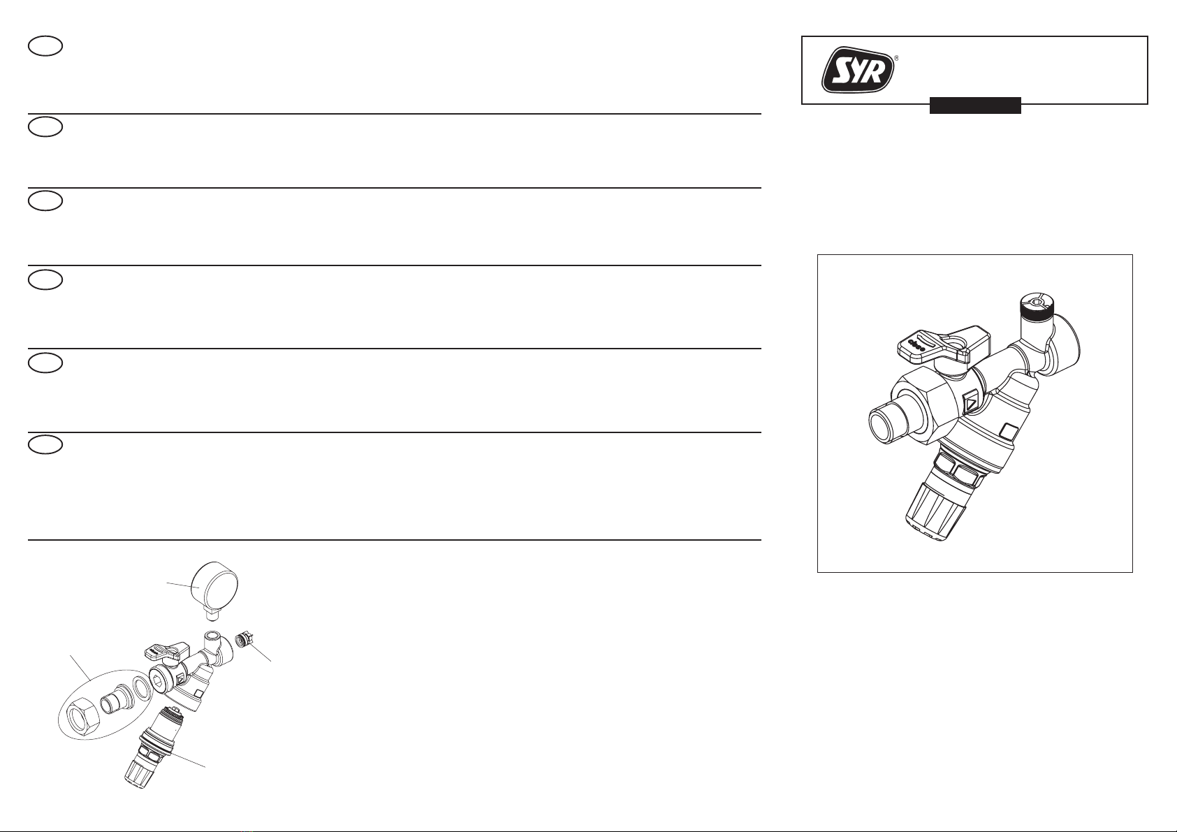
Wartung:
Rückflußverhinderer: Absperrung (1) schließen und Prüfstopfen
entfernen.
Druckminderer:
Absperrung schließen. Funktionsteil (2) lösen und herausneh-
men. Reinigung der Funktionseinheit nur mit klarem, kalten
Wasser ohne Reinigungsmittel.
Installation: Connect the Filling-Group to the
closed-circuit-system according to the direction of flow:
to fill the heating system, connect it to the potable water pipe by
means of a hose connection. When filling is completed, remove
the hose connection.
GB
D
Operation: for setting the outlet pressure, pull the adjustment
handle downwards (fig. 1) to unlock and turn counterclockwise
(-) to the stop, open and close again the draw-off point behind
the pressure reducing valve. Turn counterclockwise to decrease
and clockwise (+) to increase the pressure until the desired
pressure is reached (fig. 2), then lift the pressure adjustment
handle for re-locking (fig.3).
Maintenance:
Check valve: Close isolating valve (1) and remove test plug.
Pressure reducer: Close isolating valve. Remove pressure
reducer cartridge (2). Use cold water only for any cleaning work.
FInstallation: Raccorder le groupe de remplissage au
système à circuit fermé en tenant compte du sens
d'écoulement de l'eau. Pour remplir l'installation de chauffage,
raccorder celle-ci à la conduite d'eau potable au moyen d'un
tuyau flexible. Démonter ce dernier lorsque le remplissage est
terminé.
Utilisation: pour régler la pression: tirer le bouton de réglage
vers le bas pour débloquer (fig.1), tourner vers le moins (-)
jusqu'à la butée, ouvrir et refermer le point de puisage derrière
le réducteur de pression, tourner vers le plus(+) ou le moins
(-) jusqu'à obtention de la pression désirée (fig. 2), puis pousser
le bouton de réglage vers le haut pour bloquer à nouveau (fig.3).
Entretien:
Clapet anti-retour: Pour l'examiner, fermer le robinet d'arrêt (1).
Retirer le bouchon d'inspection.
Réducteur de pression: Fermer le robinet d'isolement. Retirer
la cartouche (2). Nettoyer à l'eau froide seulement.
GR
Εγκατáσταση: Συνδéστε τον αυτóματο πλ
ρωσης σταθερá στην εγκατáσταση,
λαμβáνοντας υπóψη την ρο του νεροú. ´Οσο
διαρκεí η πλρωση της εγκατáστασης, ο αυτóματος
πρéπει να εíναι συνδεδεμéνος με το δíκτυο πóλεως,
κατá προτíμηση με εúκαμπτο σωλνα.
Συντρηση βαλβíδας αντεπιστροφς
Κλεíστε τον διακóπτη 1 και απομακρúνετε την
βαλβíδα αντεπιστροφς.
Μειωτς πíεσης:
Κλεíστε τον διακóπτη του αυτóματου πλρωσης.
Αφαιρéστε το εξáρτημα 2 και καθαρíστε το με
καθαρó, κρúο νερó, χωρíς απορρυπαντικá.
EInstalación: El grupo de llenado debe instalarse en
el dispositivo de llenado de la instalación. Se conectará
a la red de agua de usos doméstico con un acoplamiento de
manguera. Esta conexión se desmontará después de
terminado el proceso de llenado.
Mantenimiento:
Dispositivo de retención: Cerrar las llaves de paso y sacar la
válvula antirretorno (1).
Valvula reductora: Cerrar las llaves de paso. Desenroscar y
sacar la unidad funcional. Aclarar la unidad funcional (2)
solamente con agua clara, fria y sin detergentes.
Ajuste: Para desbloquear tirar por el mango hacia abajo
(imágen 1) y girar en sentido menos (-) hasta el tope; abrir un
grifo posterior a la valvula reductora y volver a cerrarlo.
Girar el mango de selección hacia más (+) o hacia menos (-
) hasta alcanzar la presión deseada (imágen 2), luego empujar
de nuevo el mango hacia arriba para bloquearlo (imágen 3).
PL Zawór nape³niania instalacji automatyzuje proces na-
pe³niania instalacji grzewczych. Wbudowany reduktor
ciœnienia umo¿liwia utrzymywanie w³aœciwego ciœnienia
nape³nianej instalacji.
Instalacja: Zawór 2128 musi byæ po³¹czony z instalacj¹ wody
pitnej tylko podczas procesu nape³niania lub uzupe³niania
wody w z³adzie. Po zakoñczeniu nape³niania instalacji nale¿y
zamkn¹æ zawór odcinaj¹cy w armaturze, a nastêpnie od³¹czyæ
w¹¿ razem ze œrubunkiem.
Obs³uga:Wcelunastawyciœnienia wyjœciowego nale¿y ci¹gn¹c
w dó³ odblokowaæ pokrêt³o regulacyjne(rys.1). Obrót pokrêt³a w
kierunku (-) obni¿a, a w (+) podnosi nastawê ciœnienia wyjœcio-
wego (rys.2). Przy obni¿eniu nastawy ciœnienia nale¿y chwilowo
obni¿yæ ciœnienie (np. poprzez otwarcie dowolnego punktu
poboru) za reduktorem by móc zaobserwowaæ zmianê nastawy.
Po nastawieniu w³aœciwego ciœnienia pokrêt³o regulacyjne
wcisn¹æzpowrotemwgórê(rys.3)wceluzablokowanianastawy.
Obs³uga:
Zawór zwrotny: Zamkn¹æ zawór odcinaj¹cy i otworzyæ króciec
kontrolny (1). Wyciek wody oznacza uszkodznie zaworu - zawór
nale¿y wymieniæ.
Reduktorciœnienia:Wzrostciœnieniamo¿e wynikaæz zabrudzenia
reduktora. Zamkn¹æ zawór odcinaj¹cy i zalecany, zamontowany
zawór odcinaj¹cy za zaworem nape³niania . Po zdemontowaniu,
wk³ad reduktora ciœnienia (2) oczyœciæ u¿ywaj¹c zimnej wody.
Wymyæ elementy wewnêtrzne, a zw³aszcza filtr siatkowy.
Ρúθμιση μειωτ πíεσης:
Για απασφáλιση τραβξτε την λαβ προσ τα κáτω
εικóνα 1 και γυρíστε την προσ το μεíον - μéχρι
το τéλοσ της διαδρομς. Ανοíξτε το νερó σε κáποιο
σημεíο μετá τον μειωτ πíεσης, ξανακλεíστε το,
γυρíστε την λαβ προς το συν +  το μεíον éως óτου
επιτευχθεí η επιθυμητ πíεση και κατóπιν ασψαλíστε
την λαβ σπρẃχνοντáς την ξανá προς τα πáνω.
1
2
123
0712 - Printed in Germany 9.2128.00
Betriebstemp.: max. 80°C; Eingangsdruck: max. 16 bar; Aus-
gangsdruck: 1,0 - 5,0 bar.
Die Füllgruppe darf nur für die Dauer des Füllvorgangs mit der
Trinkwasserleitung verbunden werden. Nach Beendigung des
Füllvorgangs, Zuleitung absperren und Schlauchverschraubung
abnehmen.
ARMATUREN
Made in Germany
Gebrauchsanleitung
Instructions for use
Mode d'emploi
Οδηγíες χρσης
Instrucciones de uso
Instrukcja obs³ugi
2128
Füllgruppe
Filling-Group
Groupe de remplissage
Αυτóματος πλρωσης
Grupo de llenado
Zawór nape³niania instalacji
Hans Sasserath & Co KG
Tel.: +49 2161 6105-0 Fax: +49 2161 6105-20
Mühlenstrasse 62 41352 Korschenbroich
Internet: www.syr.de email: [email protected]
Die Installation und Wartung darf nur durch einen
autorisierten Fachbetrieb vorgenommen werden.
Die Verpackung ist Transportschutz. Bei starker Beschädigung
der Verpackung, Armatur nicht einbauen.
GB
D
F
GR
E
Only qualified personnel is authorised to install and
service the device.
A special packaging protects the product for transport. If the
packaging would be seriously damaged, do not install.
Seul un personnel qualifié est autorisé à effectuer
l'installation et la maintenance du produit.
Un emballage spécial sert de protection pour le transport. Si cet
emballage est fortement endommagé, ne pas installer le
produit.
Service temp.: max. 80°C; inlet pressure: max. 16 bar; outlet
pressure: 1.0 - 5.0 bar.
The Filling-Group shall only be connected to the potable water
pipe for filling the heating installation. When filling is completed,
isolate the inlet pipe and remove the hose connection.
Temp. de service: max. 80°C; pression d'entrée: max. 16 bar;
pression de sortie: 1,0 - 5,0 bar.
Le raccordement du groupe de remplissage à la conduite d'eau
potable n'est autorisé que pour la durée du remplissage.
Lorsque l'installation de chauffage est remplie, obturer la
conduite d'arrivée d'eau et retirer le flexible raccordé.
Η εγκατáσταση πρéπει να γíνεται μóνο απó
εξουσιοδοτημéνους τεχνικοúς. Η συσκευασíα
αποτελεí προστατευτικó υλικó κατá την μεταφορá.
Σε περíπτωση που η συσκευασíα éχει υποστεí
σημαντικ ζημιá, το εξáρτημα να μην εγκαθíσταται.
Θερμοκρασíα λειτουργíας: max. 80°C, Πíεση εισóδου:
max. 16 bar, Πíεση εξóδου: 1,0 - 5,0 bar.
Ο αυτóματος πλρωσης πρéπει να εíναι
συνδεδεμéνος με το δíκτυο πóλεως καθ óλη την
διáρκεια πλρωσης. Η σúνδεση μπορεí να αφαιρεθεí
μετá το τéλος της πλρωσης της εγκατáστασης.
Instalación y mantenimiento sólo pueden ser realizados
por personal autorizado. El embalaje sirve de protección durante
el transporte. El apartado no debe de ser instalado si el
embalaje muestra daños graves.
Temperatura de servicio: max. 80°C, Presión de en-trada:
max. 16 bar, Presión de salida: 1,0 - 5,0 bar.
El dispositivo de llenádo solamente debe de ser acoplado a la
tuberia de agua potable durante el proceso de alimentación.
Despues de finalizar el proceso de alimentación cortar el
suministro de agua y desconeczer el roscado de manguera.
PL Instalacja i obs³uga mo¿e byæ wykonywana jedynie
przez autoryzowany zak³ad instalacyjny.
Opakowanie pe³ni rolê ochronn¹ podczas transportu.
W przypadku znacznego uszkodzenia opakowania nale¿y
odst¹piæ od instalacji armatury.
Temperatura pracy: maks.80oC; Ciœnienie wejœciowe:
maks.25 bar; Ciœnienie wyjœciowe: 1,0 - 5,0 bar; Media: woda,
powietrze sprê¿one, olej opa³owy, neutralne nieklej¹ce p³yny i
gazy. Zawór nape³niania instalacji mo¿e byæ po³¹czony z
instalacj¹ wody pitnej tylko podczas procesu nape³niania lub
uzupe³niania wody w z³adzie. Po zakoñczeniu nape³niania
instalacji nale¿y zamkn¹æ zawór odcinaj¹cy w armaturze, a
nastêpnie od³¹czyæ w¹¿ razem ze œrubunkiem.
0312.20.933
DN 15 0814.15.900
DN 20 0812.20.900
6628.00.901
0312.10.901
optional
optional
optionnelle
Ελευθερς Επιλογς
opcional
opcjonalnie

Other SYR Plumbing Product manuals

SYR BA 6600 User manual

SYR

SYR BA 6600 User manual

SYR 315 User manual

SYR

SYR 315 User manual

SYR HygBox Connect User manual

SYR

SYR HygBox Connect User manual

SYR HygBox Connect Installation guide

SYR

SYR HygBox Connect Installation guide

SYR 2128 User manual

SYR

SYR 2128 User manual

Popular Plumbing Product manuals by other brands

Oras Vienda Installation and maintenance guide

Oras

Oras Vienda Installation and maintenance guide

Delta In2ition 58620 PK Series manual

Delta

Delta In2ition 58620 PK Series manual

Delta MultiChoice R18224 Series parts list

Delta

Delta MultiChoice R18224 Series parts list

Delta 28996LF manual

Delta

Delta 28996LF manual

IB RUBINETTI MARMO 306 Fitting instructions

IB RUBINETTI

IB RUBINETTI MARMO 306 Fitting instructions

ESS Easy Drain Multi TAF EDMTAF2000 Installation advice

ESS

ESS Easy Drain Multi TAF EDMTAF2000 Installation advice

Rubi KROnos RKR77 Installation

Rubi

Rubi KROnos RKR77 Installation

Franke 2030005623 Installation and operating instructions

Franke

Franke 2030005623 Installation and operating instructions

KWC QBIX/QBIX-ART 11.253.033.006 specification

KWC

KWC QBIX/QBIX-ART 11.253.033.006 specification

Riobel PB66C-EM installation guide

Riobel

Riobel PB66C-EM installation guide

Brizo Charlotte 85885 Series installation instructions

Brizo

Brizo Charlotte 85885 Series installation instructions

EOS Multicup Installation and operation instruction

EOS

EOS Multicup Installation and operation instruction

Symmons Duro 361SH Operation & maintenance manual

Symmons

Symmons Duro 361SH Operation & maintenance manual

miseno MNOSH425ECP quick start guide

miseno

miseno MNOSH425ECP quick start guide

Sloan Wes-115 installation instructions

Sloan

Sloan Wes-115 installation instructions

Sunlighten Signature Series user manual

Sunlighten

Sunlighten Signature Series user manual

CIFIAL 3215005 Assembly and instruction manual

CIFIAL

CIFIAL 3215005 Assembly and instruction manual

Helvex 310-32 installation guide

Helvex

Helvex 310-32 installation guide

manuals.online logo
manuals.online logoBrands
  • About & Mission
  • Contact us
  • Privacy Policy
  • Terms and Conditions

Copyright 2025 Manuals.Online. All Rights Reserved.