Systema EOLO LX User manual

ENGLISH
Instruction manual
installation, use and maintenance
Rev. 00ITIT20210827
EOLO LX
HEAT EXCHANGER
GAS UNIT

Symbols used in the manual
Important
Important information and recommended practice.
READ CAREFULLY BEFORE USE; KEEP THE MANUAL FOR FURTHER REFERENCE
Before installation, make sure that the local distribution conditions, the nature of the gas
and the pressure correspond to the settings of the device.
Systema Polska reserves a right to modify product content for the purposes of product
improvement at sole discretion without preliminary notice.
Systema Polska Sp. z o.o.
ul. Długa 5
98-220 Zduńska Wola
NIP: 829-150-55-41
(+43) 824 72 87
In this manual, the word DANGER combined with the danger symbol indicates a danger with a high
level of risk which, if not avoided, will result in death or severe injury.
WARNING
In this manual, the word WARNING combined with the warning symbol indicates a danger with a me-
dium level of risk, which, if not avoided, could result in death or severe injury.
CAUTION
In this manual, the word WARNING combined with the warning symbol indicates a danger with a me-
dium level of risk, which, if not avoided, could result in death or severe injury.
Note
Useful reference information for proper device operation.
DANGER

3
I
Systema Polska Sp. z o.o.
Lennox rev. 00ITIT20210827
SOMMARIO
1 GENERAL RULES..............................................................................................................................................................................................................5
1.1 EXPLOITATION ..........................................................................................................................................................................................................6
1.2 TERMS AND DEFINITIONS ......................................................................................................................................................................................7
2 FEATURES .......................................................................................................................................................................................................................8
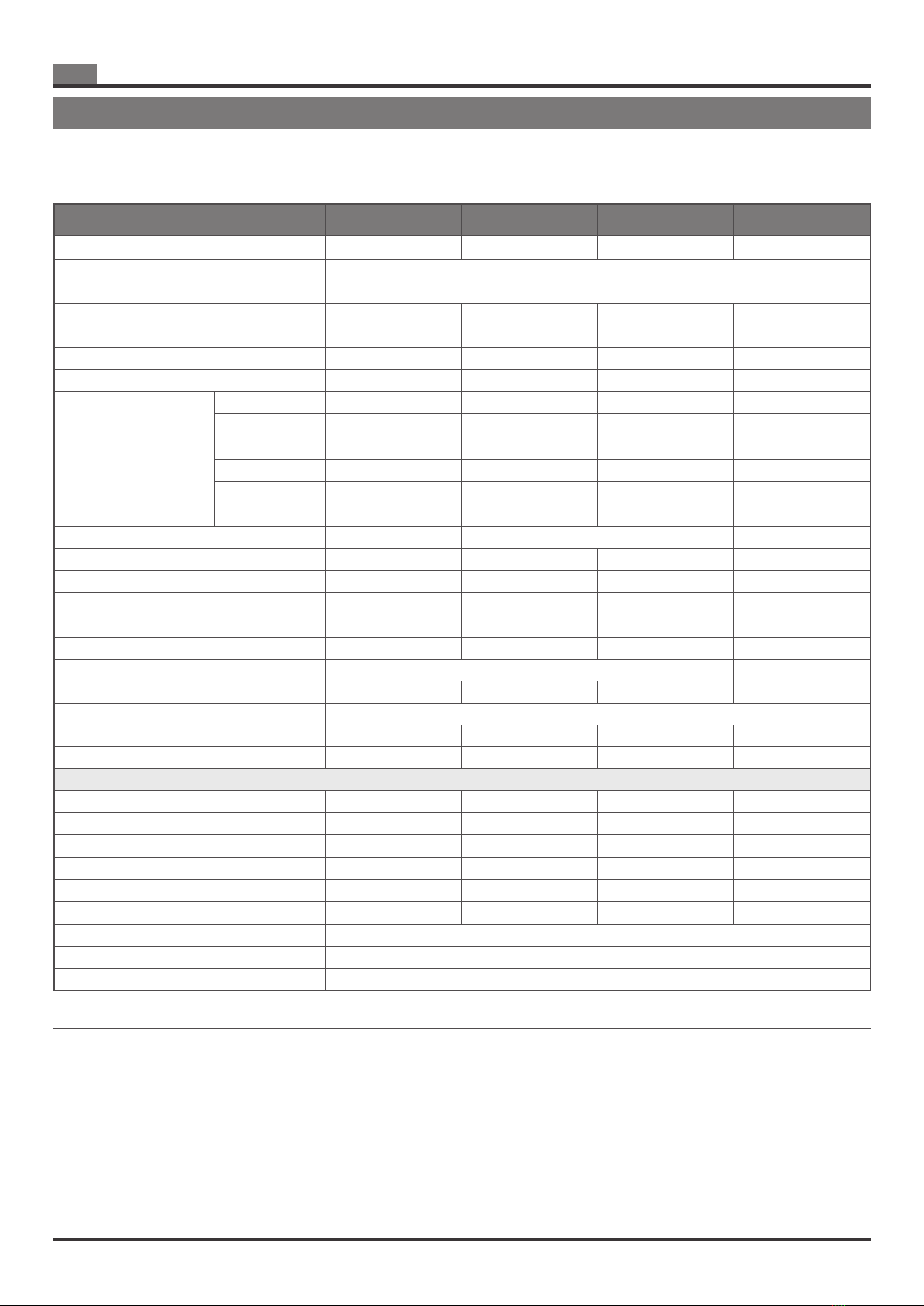
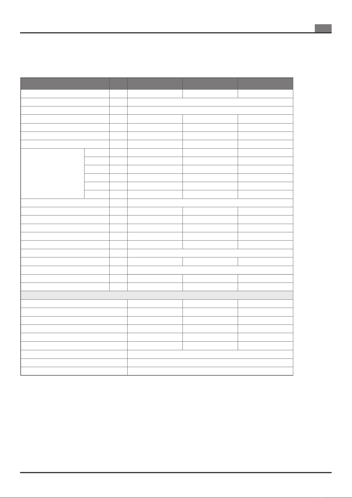
2.1 TECHNICAL DATA......................................................................................................................................................................................................8
2.2 IDENTIFICATION PLATE AND INFORMATION LABELS ....................................................................................................................................... 10
2.3 OVERALL DIMENSINS..............................................................................................................................................................................................12
2.4 COMPONENT ARRANGEMENT............................................................................................................................................................................... 13
2.5 LIST OF COMPONENTS ...........................................................................................................................................................................................14
2.6 BURNER...................................................................................................................................................................................................................... 16
2.6.1 VIP 1 HW................................................................................................................................................................................................................16
2.6.2 VIP 2 HW................................................................................................................................................................................................................17
2.6.3 VIP 3 HW a/b..........................................................................................................................................................................................................18
2.6.4 VIP 4 HW a.............................................................................................................................................................................................................19
2.6.5 VIP 4 HW b.............................................................................................................................................................................................................20
2.6.6 VIP 5 HW a.............................................................................................................................................................................................................21
3 WIRING .......................................................................................................................................................................................................................22
3.1 SCP674V130B1 CARD CONNECTIONS (MAIN BOARD)....................................................................................................................................... 24
3.2 SCP674V202MB SLAVE CARD CONNECTIONS.................................................................................................................................................... 26
4 OPERATION OF THE APPLIANCE .................................................................................................................................................................................. 27
4.1 CHARACTERISTICS OF THE COMMAND AND CONTROL BOARD SCP674V130B1........................................................................................ 27
4.2 SIGNALS ON THE DISPLAY..................................................................................................................................................................................... 28
4.3 MAINBOARD OPERATION ....................................................................................................................................................................................... 29
4.4 BURNER SHUTDOWN - COMBUSTION CHAMBER POST VENTILATION.........................................................................................................29
4.4.1 Burner shutdown due to the opening of a safety contact .......................................................................................................................................29
4.4.2 Burner shutdown due to burner fan speed exceeding............................................................................................................................................30
4.5 RESET OF BURNER..................................................................................................................................................................................................30
4.6 BURNER OPERATING PARAMETERS.................................................................................................................................................................... 30
4.7 SCP674V202MB SLAVE BOARD FEATURES ......................................................................................................................................................... 32
4.7.1 Main features..........................................................................................................................................................................................................32
4.7.2.1 Serial conguration of devices................................................................................................................................................................................33
4.7.2.2 Network / slave device addresses..........................................................................................................................................................................33
4.7.2.3 Exception codes .....................................................................................................................................................................................................33
4.7.2.4 COMMAND DESCRIPTION ...................................................................................................................................................................................34
4.8 SCP674V202MB SLAVE CARD PROGRAMMING .................................................................................................................................................. 35
4.8.1 SCP674V202MB card encoding for network operation..........................................................................................................................................35
4.8.2 DIP Switch Conguration 3.....................................................................................................................................................................................37
4.8.3 Conguration DIP Swicht 4.....................................................................................................................................................................................37
4.8.4 Menu SET-POINT: SEt ...........................................................................................................................................................................................37
4.8.5 FUNCTIONS menu: Fnc - burner RESET..............................................................................................................................................................38
4.8.6 Menu INFO: inFo....................................................................................................................................................................................................38
4.8.7 Menu ALARMS: ALSt ............................................................................................................................................................................................. 39
4.8.8 Menu PARAMETERS .............................................................................................................................................................................................39
4.8.9 Burner operation mode (PWM)...............................................................................................................................................................................40
5 GAS INSTALLATION.......................................................................................................................................................................................................... 42
5.1 CONNECTION OF THE APPLIANCE ....................................................................................................................................................................... 42
6 INSTALLATION...................................................................................................................................................................................................................45
6.1 PRELIMINARY UNLOADING OPERATIONS........................................................................................................................................................... 45
6.1.1 Packaging...............................................................................................................................................................................................................45
6.1.2 Packaging dimensions............................................................................................................................................................................................46
6.1.3 Handling with forklift ...............................................................................................................................................................................................46
6.1.4 Exchanger handling with eyebolts..........................................................................................................................................................................47
6.2 CONDENSATE DRAIN...............................................................................................................................................................................................48
6.2.1 Condensate drain connection.................................................................................................................................................................................48
6.2.2 Condensate stagnation in the exchanger...............................................................................................................................................................49
6.2.3 Frost protection.......................................................................................................................................................................................................49
6.2.4 Discharge into the drainage system .......................................................................................................................................................................49
6.3 EXHAUST DUCTS...................................................................................................................................................................................................... 49
6.4 APPLICATION IN AIR CONDITIONING SYSTEMS WITH REFRIGERANT GAS.................................................................................................51
6.5 CONDITIONS INSTALLING THE APPLIANCE IN AN EXTERNAL HOUSING AS AIR HANDLING UNIT..........................................................52
7 TESTING AND START-UP OF THE SYSTEM.................................................................................................................................................................. 53
7.1 DRY TEST (WITHOUT FUEL GAS) ..........................................................................................................................................................................53
7.2 PRELIMINARY OPERATIONS ..................................................................................................................................................................................53
7.3 STARTING UP THE APPLIANCE..............................................................................................................................................................................54
7.4 ADJUSTMENTS ......................................................................................................................................................................................................... 54
7.4.1 Gas unit with gas valves VR4205VE5002B and VK4415V1002B.......................................................................................................................... 55
7.4.2 Gas unit with gas valve VR415VE5024..................................................................................................................................................................56
7.5 POSITION OF ELECTRODES .................................................................................................................................................................................. 57
8 MAINTENANCE ..................................................................................................................................................................................................................58
8.1 FUEL CHANGE...........................................................................................................................................................................................................60
8.1.1 Replacement of the Venturi for gas valve VK4205VE5002B..................................................................................................................................................61
8.1.2 Pre-settings of gas valve VK4205VE5002B after gas type change. ......................................................................................................................................62
8.1.3 Replacement of the Venturi for gas valve VK4415V1002B ................................................................................................................................................... 63
8.1.4 Pre-settings of gas valve VK4415V1002B after gas type change..........................................................................................................................................64
8.1.5 Replacement of the Venturi for gas valve VR415/ VR420 ..................................................................................................................................................... 65
8.1.6 Pre-settings of gas valve VR415/VR420 after gas type change. ...........................................................................................................................................66
8.2 FAULTS AND REMEDIES..........................................................................................................................................................................................67

4
I
Systema Polska Sp. z o.o.
Lennox rev. 00ITIT20210827
9 WARRANTY .......................................................................................................................................................................................................................69
9.1 OBJECT AND DURATION OF THE WARRANTY.................................................................................................................................................... 69
9.2 WARRANTY EXCLUSIONS.......................................................................................................................................................................................69
9.3 OPERATION AND EFFECTIVENESS OF WARRANTY.......................................................................................................................................... 69
9.4 RESPONSIBILITY ......................................................................................................................................................................................................69
10 SHUTDOWN AND DISPOSAL...........................................................................................................................................................................................70
10.1 SHUTDOWN ...............................................................................................................................................................................................................70
10.2 DISPOSAL...................................................................................................................................................................................................................70

5
1
Systema Polska Sp. z o.o.
Lennox rev. 00ITIT20210827
GENERAL RULES
1 GENERAL RULES
These appliances are designed and built according to EU Regulation 2016/426 (GAR).Please, read this manual before use
of the device.
■It is mandatory to follow the instructions in this manual, particularly concerning safety rules.
■In no case will Systema be responsible for any direct or indirect damage to humans, animals, or property, resulting from
user’s failure to follow the instructions given in this manual.
■This Operation Manual is an important and integral part of the device and should be stored carefully the installation for
further reference.
■Please, carefully read the instructions and warnings contained in this manual before installation and use of the device, as
they provide important information regarding safety, installation, operation, and maintenance.
■If the manual is lost, please contact the manufacturer immediately.
■In case of change of owner or new tenant, please provide all the documentation related to the heating device to the new
owner/tenant.
■When transferring the product to a new user please check the integrity and completeness of the device and its compo-
nents. If the device and/or its components do not comply with the requirements, contact the seller.
■When installation work is complete, the installer should provide the owner with the necessary documentation to certify
that installation has been carried out in a workmanlike manner and complies with the applicable country regulations.
■Excessively high temperatures in a heated space may be harmful to health and are a waste of energy. We recommend
using your device reasonably.
■The manufacturer is responsible for the compliance of its product with the applicable rules at the time of the product
selling.
■Compliance with the current legislation and regulations for the design of the systems, its installation, operation, and
maintenance are the sole responsibility of the designer, installer and user.
■Distribution of this product without prior notice to the manufacturer is prohibited. In the country where the device was
nally installed specic documentation is required, depending on the country of destination of the product.
■Additional devices installed in the same room or directly communicating rooms are considered as a single system, with
a heat output equal to the sum of the thermal ows of the individual devices.
WARNING
■To ensure proper behavior of devices, it is important to strictly follow the manufacturer's instructions, to use original ac-
cessories and spare parts and to have the system maintained by qualied personnel (at least once a year).
■Do not install devices in areas, intended for trade or industrial activities, where the storage of materials and processing
thereof pose the risk of gas, vapor or dust generation, which can cause res or explosions.
■It should be possible to exchange air regularly in sites where the devices are installed, according to the current regula-
tions.
■Installation, routing of gas pipes, electrical connection, the initial startup, and maintenance should be carried out by qua-
lied personnel, following the instructions in this manual and should comply to the current national and local regulations
of the country where the system is installed.
■Gas supply and electrical connections should comply with the current national and local regulations of the country where
the system is installed. Where required, they should be designed by a qualied professional.
■The systems (gas pipes, power sources, etc.) should be designed without creating obstacles or risks to personnel.
■Do not use gas pipes for grounding of electric devices.
■Before starting devices, please check:
– that the parameters of the electric power supply and gas supply networks are compatible with the instructions given in
this manual and on the devices’ nameplates;
– that tightness of the gas supply system complies with the applicable standards and dimensions, and is equipped with
all the necessary safety and control devices required by current regulations;
– the proper routing and operation of gas exhaust and air intake pipelines;
– the correct realization and operation of the delivery conduit of the condensate drain.
■This device should be used for its intended purpose only. Any other use is considered improper and therefore dangerous.
■In no case will the manufacturer be subjected to civil or criminal liability for any damage to humans or animals due to
incorrect installation, adjustment and maintenance, modications and tampering, use of non-original spare parts and
accessories, incorrect and/or improper use of the device, noncompliance with the manufacturer’s instructions and inter-
vention of unqualied personnel.
■If the device is not used for long periods, it is recommended to perform the following operations:
– turn the device main power switch and system master switch to OFF;
– close the main shut-o gas valve.
■After long periods when the device was not used we recommend to contact the technical support or qualied technical
personnel to put the device back into operation.
■If the device is stopped and/or malfunctioning, please turn it o. Any repair or replacement of components should be

6
1
Systema Polska Sp. z o.o.
Lennox rev. 00ITIT20210827
GENERAL RULES
carried out only by qualied personnel using only original spare parts. Failure to follow these rules may compromise the
safety of the device.
■Do not leave packaging elements (nylon, polystyrene foam, wood, staples, etc.) within the reach of children and/or unat-
tended, as they can be potential sources of danger and pollution. Collect and keep them in a special place.
Keep in mind that the use of electricity and gas-operated products must comply with some basic rules:
■The product shouldn't be used by disabled persons without assistance and children.
■If there is a smell of gas, do not operate electrical devices (such as switches), electrical appliances, etc. In such cases
proceed as follows:
– open the doors and windows to ensure air change in the premises;
– close the main shut-o gas valve.
– in case of a breakdown do not try to manage it by yourself, but immediately call qualied personnel or technical support.
■Do not touch the device barefoot and with wet or moist parts of the body.
■Do not attempt to clean or service the device when it is connected to the electric power supply. To carry out these opera-
tions it is rst necessary to set the system master switch to OFF and close the supply of the fuel gas.
■It is strictly prohibited to tamper with or modify the safety and control systems without authorization and specic in-
structions from the device manufacturer.
■Do not pull, detach or twist the device’s electrical cables, even when they are disconnected from a power source.
■Do not open the device while it is in operation, rst set the main power switch to OFF.
■Do not place objects on top of the device, or insert them in exhaust and combustion air intake pipes.
■Do not touch the combustion chamber, exhaust pipe or other hot parts during the device operation, as hot surfaces can
cause burns. These surfaces may remain hot even after the device is turned o. Turn o the system in case of activities
conducted near the equipment and continuously monitor the control panel to prevent it from being turned on.
■Do not tamper with the device control system at the control panel during maintenance. During maintenance, the service
technician must place a warning sign on the system control panel with the following message: “The device is under main-
tenance. DO NOT operate the device control panel!”.
■Do not use the xing system to support the weight of other devices or equipment. Specications for the xing system in
this manual take into account only the weight of one device with the exhaust and air intake pipes.
■Do not use the device as a support base and/or walkable surface.
■Do not block/cover the blower intake or air supply inlet.
Note
To switch o the device, always use the room thermostat, not the main switch on the ground
control panel. The reason is that overheating of the combustion chamber can occur with sub-
sequent damage to the device itself.
1.1 EXPLOITATION
The condensing gas unit EOLO LX series are heat generators designed to be used as a module for
heating inside the air handling units and roof-tops.
The power is regulated automatically, modulating the heat input from minimum to maximum.
Thanks to the use of a premixed burner, specially designed for this specic application, high combustion e-
ciency is obtained.
In order to function, the unit must be connected to a gas supply system, to the electricity network, as well as
to a ue gas discharge pipe and a condensate drain pipe.
Note
Insert the EOLO LX series gas units in a system with an adequate air ow rate (see the nomi-
nal air ow rate indicated in tables 2.1 and 2.2)

7
1
Systema Polska Sp. z o.o.
Lennox rev. 00ITIT20210827
GENERAL RULES
1.2 TERMS AND DEFINITIONS
Tab. 1.1 Denition
TERMS DESCRIPTION
Damage Physical damage, personal injury or deterioration of property, and/or contamination of the environment.
Danger A potential source of damage.
Qualied professional
A person who is properly trained, prepared and/or has relevant technical experience in the subject, allowing him to
perceive risks and avoid dangers arising during the use of the product, and who has the necessary technical and pro-
fessional certicates, if this is stipulated by the current legislation.
Risk Combination of the probability of the damage occurrence and its severity.
User Person or entity using the devices.
Modulatig
The device can automatically adjust its heat output in a certain range, depending on the actual temperature of the airow
supplied to the room, or the actual temperature of the room, based on the control values set from the ground control
panel.
GCV (Unit MJ/m³)
Higher caloric value, the total amount of heat released by a unit quantity of fuel, when it is burned completely with
oxygen, and when the products of combustion are returned to ambient temperature. This quantity includes the heat of
condensation of any water vapor contained in the fuel and of the water vapor formed by the combustion of any hydrogen
contained in the fuel.
NCV (Unit MJ/m³) Lower caloric value, the total amount of heat released by a unit quantity of fuel with a certain amount of water vapor,
when it is burned completely with oxygen and when the products of combustion are not returned to ambient temperature.
Nominal Heat Input
(unit kW) It is the product of the lower caloric value (NCV) of the fuel used and the ow rate of fuel burned.
Nominal heat output
(unit kW) It corresponds to the reduced heat input of the heat output lost to the chimney.
Rated heating capacity (kW) rated heating capacity (Prated,h) means the heating capacity of a heat pump, warm air heater or fan coil units when provi-
ding space heating at ‘standard rating conditions’, expressed in kW; (simbolo Prated,h)
Minimum capacity (kW) minimum capacity’ means the minimum heating capacity of the warm air heater (Pmin), expressed in kW;
Nominal values of powers and
efciency
These are the maximum power and efciency values of an appliance specied and guaranteed by the manufacturer for
continuous operation.
Warm air heater Warm air heater means an air heating product that transfers the heat from a heat generator directly to air and
incorporates or distributes this heat through an air-based heating system;
B1 warm air heater
B1 warm air heater’ means a warm air heater using gaseous/liquid fuels specically designed to be connected to a
natural draught ue that evacuates the residues of combustion to the outside of the room containing the B1 warm
air heater and for drawing the combustion air directly from the room; a type B1 warm air heater is marketed as
a B1 warm air heater only.
C2 warm air heater
C2 warm air heater’ means a warm air heater using gaseous/liquid fuels specically designed for drawing the
combustion air from a common duct system to which more than one appliance is connected and extracting ue gas to
the duct system; a type C2 warm air heater is marketed as a C2 warm air heater only
C4 warm air heater
C4 warm air heater’ means a warm air heater using gaseous/liquid fuels specically designed for drawing the
combustion air from a common duct system to which more than one appliance is connected and extracting ue gas to
another pipe of the ue system; a type C4 warm air heater is marketed as a C4 warm air heater only;
Slave Card (SCP674V202MB) installed on the machine equipped with a port for connecting the device to a serial network.

8
2
Systema Polska Sp. z o.o.
Lennox rev. 00ITIT20210827
FEATURES
2.1 TECHNICAL DATA
Description Unit EOLO LXC 50 EOLO LXD 70 EOLO LXE 90 EOLO LXE+ 110
Operation - Range rated Range rated Range rated Range rated
Category - see tab. 5.1, pag. 49
Type - B23
Nominal heat input (NCV) kW 50 (45)* 70 (65)* 90 110
Min. heat input (NCV) kW 10 14 18 22
Eftient at nominal power %96 96 96 96
Eftient at min. power % 109 109 109 109
Gas consumption
15 °C 1013 mbar
G 20 m³/h 5,29 7,41 9,52 11,64
G 25 m³/h 6,15 8,62 11,08 13,54
G 2.350 m³/h 7,35 10,29 13,23 16,17
G 27 m³/h 6,45 9,04 11,62 14,20
G 30 kg/h 3,94 5,52 7,10 8,67
G 31 kg/h 3,88 5,44 6,99 8,55
Supply gas pressure mbar see tab. 5.1, pag. 49
Arow min. / max. m³/h 4200/6900 7100/11100 13500/16000 20500/24500
Diameter of gas connection Inch 3/4 3/4 3/4 3/4
Exhaust pipe diameter mm 100 100 100 100
Maximum pressure in exhoust Pa 120 120 120 120
Exhaust mass ow (*) kg/h 86 119 155 187
El. Supply V/Hz 2/PE ~50Hz 400V
Nominal electrical power kW 0,065 0,135 0,173 0,170
Operating temperature (min ÷ max) °C -20÷40
Noise level (1 meter from the appliance) dB(A) 48 51 52 53
Weight kg 100 120 155 155
MAIN COMPONENTS OF THE UNIT
Exchanger LXC35-30-075_5x5 LXD35-30-110_5x5 LXE35-30-135_5x5 LXE35_30_135 5x5
Burner VIP 1 HW a VIP 2 HW VIP 3 HW a VIP 3 HW b
Burner head Ø129 x 120 Ø154 x 120 Ø159 x H 120 Ø159 x H 120
Gas valve VK4205 VK4205 VK4415 VK4415
Gas blower NRG 118 RG 148 NRG 137 NRG 137
Venturi 45900451-56 45900451-56 45900450N-020 45900450N-020
Flame controler Genius M82
Control electronics (motherboard) SCP674V130B1
Automatic control electronics (slave board) SCP674V202MB
Tab. 2.1 Tecnical data (1 of 2)
3 CARATTERISTICHE2 FEATURES
(*) For gases G25 / G27 / G2.350
(**) Referred to methane G 20

9
2
Systema Polska Sp. z o.o.
Lennox rev. 00ITIT20210827
FEATURES
Description Unit EOLO LXF 130 EOLO LXG 170 EOLO LXH 230
Operation Range rated Range rated Range rated
Category vedi tab. 5.1, pag. 49
Type B23
Nominal heat input (NCV) kW 130 170 230
Min. heat input (NCV) kW 26 34 46
Eftient at nominal power %96 96 97
Eftient at min. power % 109 109 109
Gas consumption
15 °C 1013 mbar
G 20 m³/h 13,76 17,99 24,34
G 25 m³/h 16,00 20,92 28,31
G 2.350 m³/h 19,11 24,99 33,81
G 27 m³/h 16,78 21,94 29.69
G 30 kg/h 10,25 13,41 18,14
G 31 kg/h 10,10 13,21 17,87
Supply gas pressure mbar vedi tab. 5.1, pag. 49
Arow min. / max. m³/h 15000/23000 26000/28000 33000/35000
Diameter of gas connection Inch 1" 1"1/4 1"1/4
Exhaust pipe diameter mm 130 130 150
Maximum pressure in exhoust Pa 120 120 120
Exhaust mass ow (*) kg/h 220 296 382
El. Supply V/Hz 2/PE ~50Hz 400V
Nominal electrical power kW 0,180 0,250 0,250
Operating temperature (min ÷ max) °C -20÷40
Noise level (1 meter from the appliance) dB(A) 53 56 57
Weight kg 195 260 310
MAIN COMPONENTS OF THE UNIT
Exchanger LXF33-45-150_5x5 LXG35-55-175_5x5 LXH35-63-175_12x12
Burner VIP 4 HW a VIP 4 HW b VIP 5 HW b
Burner head Ø154 x H 180 Ø168 x H 180 Ø168 x H 180
Gas valve VK4415 VR415 VR420
Gas blower RG 175 RG 175 G1G 170
Venturi 45900450N-030 VMU185 VMU300
Flame controler Genius M82
Control electronics (motherboard) SCP674V130B1
Automatic control electronics (slave board) SCP674V202MB
Tab. 2.1 Tecnical data (2 of 2)
(*) Referred to methane G 20

10
2
Systema Polska Sp. z o.o.
Lennox rev. 00ITIT20210827
FEATURES
XXXXXXXXX
ul. Długa 5
98-220 Zdu ska Wola/ POLSKA
Model
Serial no.:
Year
Destination
Category
Type
Certicate no.:
Nominal heat input (Hi) [ kW ]
12
Gas network pressure
Nominal consumption max
Electrical
mbar
kg/h
m³/h
Protection
class
Max eletr. power
Classe
NOx
5
www.systemapolska.pl
Nominal heat output
(V/Hz)
(W)
2H +
DESTINATION
Device adjusted for:
12
Document int.
Category:
TYPE:
XX/11/PWProd/PWT1/2020
70LENX0100
19
DESTINATION
Device adjusted for:
YYYYYYYY
Category:
TYPE:
XXXXXXXXXXXXXXX
Document int.
XXXXXXXXX
Read the installation instructions before
installing and switching on the appliance.
For type B applications, please forsee
adequately ventilated spaces.
Device adjusted
for:
Device adjusted for:
................................ / ................................. mbar
25
50
IP20
2/PE
50Hz/400V
72
5,29 6,15
3,88 3,94
2H3+
EOLOLXC 50
XXXX XXX XX
L20H110 12
XXXXXXX
XXXXXXX
XXXXXXXXXX
XXXXXX
X X X X
X X X X
XXXXXXX
XX
XXXXXXXXX
XXXXXXXXX
XXXXXXXXX
ul. Długa 5
98-220 Zdu ska Wola/ POLSKA
Model
Serial no.:
Year
Destination
Category
Type
Certicate no.:
Nominal heat input (Hi) [ kW ]
12
Gas network pressure
Nominal consumption max
Electrical
mbar
kg/h
m³/h
Protection
class
Max eletr. power
Classe
NOx
5
www.systemapolska.pl
Nominal heat output
(V/Hz)
(W)
2H +
DESTINATION
Device adjusted for:
12
Document int.
Category:
TYPE:
XX/11/PWProd/PWT1/2020
70LENX0100
19 DESTINATION
Device adjusted for:
YYYYYYYY
Category:
TYPE:
XXXXXXXXXXXXXXX
Document int.
XXXXXXXXX
Read the installation instructions before
installing and switching on the appliance.
For type B applications, please forsee
adequately ventilated spaces.
Device adjusted
for:
Device adjusted for:
................................ / ................................. mbar
25
50
IP20
2/PE
50Hz/400V
72
5,29 6,15
3,88 3,94
2H3+
EOLOLXC 50 XXXX XXX XX
L20H110 12 XXXXXXX
XXXXXXX
XXXXXXXXXX
XXXXXX
X X X X
X X X X
XXXXXXX
XX
XXXXXXXXX
XXXXXXXXX
XXXXXXXXX
ul. Długa 5
98-220 Zdu ska Wola/ POLSKA
Model
Serial no.:
Year
Destination
Category
Type
Certicate no.:
Nominal heat input (Hi) [ kW ]
12
Gas network pressure
Nominal consumption max
Electrical
mbar
kg/h
m³/h
Protection
class
Max eletr. power
Classe
NOx 5
www.systemapolska.pl
Nominal heat output
(V/Hz)
(W)
2H +
DESTINATION
Device adjusted for:
12
Document int.
Category:
TYPE:
XX/11/PWProd/PWT1/2020
70LENX0100
19 DESTINATION
Device adjusted for:
YYYYYYYY
Category:
TYPE:
XXXXXXXXXXXXXXX
Document int.
XXXXXXXXX
Read the installation instructions before
installing and switching on the appliance.
For type B applications, please forsee
adequately ventilated spaces.
Device adjusted
for:
Device adjusted for:
................................ / ................................. mbar
25
50
IP20
2/PE
50Hz/400V
72
5,29 6,15
3,88 3,94
2H3+
EOLOLXC 50 XXXX XXX XX
L20H110 12 XXXXXXX
XXXXXXX
XXXXXXXXXX
XXXXXX
X X X X
X X X X
XXXXXXX
XX
XXXXXXXXX
XXXXXXXXX
XXXXXXXXX
ul. Długa 5
98-220 Zdu ska Wola/ POLSKA
Model
Serial no.:
Year
Destination
Category
Type
Certicate no.:
Nominal heat input (Hi) [ kW ]
12
Gas network pressure
Nominal consumption max
Electrical
mbar
kg/h
m³/h
Protection
class
Max eletr. power
Classe
NOx
5
www.systemapolska.pl
Nominal heat output
(V/Hz)
(W)
2H +
DESTINATION
Device adjusted for:
12
Document int.
Category:
TYPE:
XX/11/PWProd/PWT1/2020
70LENX0100
19 DESTINATION
Device adjusted for:
YYYYYYYY
Category:
TYPE:
XXXXXXXXXXXXXXX
Document int.
XXXXXXXXX
Read the installation instructions before
installing and switching on the appliance.
For type B applications, please forsee
adequately ventilated spaces.
Device adjusted
for:
Device adjusted for:
................................ / ................................. mbar
25
50
IP20
2/PE
50Hz/400V
72
5,29 6,15
3,88 3,94
2H3+
EOLOLXC 50 XXXX XXX XX
L20H110 12 XXXXXXX
XXXXXXX
XXXXXXXXXX
XXXXXX
X X X X
X X X X
XXXXXXX
XX
XXXXXXXXX
XXXXXXXXX
XXXXXXXXX
ul. Długa 5
98-220 Zdu ska Wola/ POLSKA
Model
Serial no.:
Year
Destination
Category
Type
Certicate no.:
Nominal heat input (Hi) [ kW ]
12
Gas network pressure
Nominal consumption max
Electrical
mbar
kg/h
m³/h
Protection
class
Max eletr. power Classe
NOx 5
www.systemapolska.pl
Nominal heat output
(V/Hz)
(W)
2H +
DESTINATION
Device adjusted for:
12
Document int.
Category:
TYPE:
XX/11/PWProd/PWT1/2020
70LENX0100
19 DESTINATION
Device adjusted for:
YYYYYYYY
Category:
TYPE:
XXXXXXXXXXXXXXX
Document int.
XXXXXXXXX
Read the installation instructions before
installing and switching on the appliance.
For type B applications, please forsee
adequately ventilated spaces.
Device adjusted
for:
Device adjusted for:
................................ / ................................. mbar
25
50
IP20
2/PE
50Hz/400V
72
5,29 6,15
3,88 3,94
2H3+
EOLOLXC 50 XXXX XXX XX
L20H110 12 XXXXXXX
XXXXXXX
XXXXXXXXXX
XXXXXX
X X X X
X X X X
XXXXXXX
XX
XXXXXXXXX
XXXXXXXXX
2.2 IDENTIFICATION PLATE AND INFORMATION LABELS
Some information labels are applied to the appliance packaging (g. 2.1).
The product identication label is applied to the device (g. 2.4) where all the identication data that distingui-
sh the device and the warning labels are indicated.
Among these indications there is the unique serial number for each product, thanks to this number the manu-
facturer can precisely identify the model and all the technical data relating to the product in case of assistance
requests. All labels must be kept intact on the device and must be replaced if they become illegible.
Together with the instruction manual, there are labels to be used when changing fuel (g.2.2).
Fig. 2.1 Labels placed on the appliance packaging
Fig. 2.2 Labels to be used for fuel changes
Fig. 2.3 Labels placed on the packaging for the obligation of individual protection devices
On the packaging there are warning symbols for the mandatory use of personal protective equipment (g.
2.3).
Footwear by
safety
Helmet of
protection
Gloves of
protection
Important
the serial number of the product is essential for an adequate and rapid assistance.

11
2
Systema Polska Sp. z o.o.
Lennox rev. 00ITIT20210827
FEATURES
Model:
Destination:
SERIAL NUMBER:
EOLO LXC 50
FRANCE
L20H11000
ul. Długa 5
98-220 Zduńska Wola / POLAND
tel. +48 43 824 72 87
www.systemapolska.pl
Systema Polska Sp. z o.o.
Model:
Destination:
SERIAL NUMBER:
EOLO LXC 50
FRANCE
L20H11000
SYSTEMA POLSKA Sp. z o.o.
ul. Długa 5
98-220 Zduńska Wola/ POLSKA
Model
Serial no.:
Year
Destination
Category
Type
Certificate no.:
Nominal heat input (Hi) [ kW ]
EOLO LXC 50
LXXXXXXX
2020
XXXXXXX
II
Device adjusted for: Gas G20 / 2,0kPa
Type of gas
Gas network pressure
Nominal gas consumption
Electrical supply
kPa
kg/h
m³/h
Protection
class
2,0
Max. eletr. power Classe
NOx
5
www.systemapolska.pl
G20 G31
XX
XXXX
Nominal heat output
(V/Hz)
(W)
3,7
2ESi3P
SERIAL NUMBER:
Model:
FRANCE
DESTINATION
Device adjusted for:
Gas G20 / 20mbar
L20H11000
EOLO LXC 50
Document int.
Category:
TYPE:
124/11/PWProd/PWT1/2020
L20H11000
70LENX0100
EOLOLXC 50
19
1450
SERIAL NUMBER:
Model:
FRANCE
DESTINATION
Device adjusted for:
Gas G20 / 20mbar
L20H11000
EOLO LXC 50
Category:
TYPE:
124/11/PWProd/PWT1/2020
Document int.
L20H11000
EOLOLXC 50
70LENX0100
19
1450
Read the installation instructions before
installing and switching on the appliance.
For type B applications, please forsee
adequately ventilated spaces.
IMPORTANT
IMPORTANT
Read the installation instructions before
installing and switching on the appliance.
For type B applications, please forsee
adequately ventilated spaces.
Adjusted for: ................................
Gas network pressure ................................mbar
G20
20mbar
Device adjusted
for:
G31
37mbar
Device adjusted for:
................................ / ................................. mbar
Adjusted for: G20
Gas network pressure 20mbar
B23
2,5
G25
50 kW
47 kW
IP00
2/PE
50Hz/400V
72
Condensing gas unit
FRANCE
5,29 6,15
3,88
ul. Długa 5
98-220 Zduńska Wola / POLAND
tel. +48 43 824 72 87
www.systemapolska.pl
Systema Polska Sp. z o.o.
II
2ESi3P
B23
II
2ESi3P
B23
XXXXXXXXX
ul. Długa 5
98-220 Zdu ska Wola/ POLSKA
Model
Serial no.:
Year
Destination
Category
Type
Certicate no.:
Nominal heat input (Hi) [ kW ]
12
Gas network pressure
Nominal consumption max
Electrical
mbar
kg/h
m³/h
Protection
class
Max eletr. power Classe
NOx
5
www.systemapolska.pl
Nominal heat output
(V/Hz)
(W)
2H +
DESTINATION
Device adjusted for:
12
Document int.
Category:
TYPE:
XX/11/PWProd/PWT1/2020
70LENX0100
19 DESTINATION
Device adjusted for:
YYYYYYYY
Category:
TYPE:
XXXXXXXXXXXXXXX
Document int.
XXXXXXXXX
Read the installation instructions before
installing and switching on the appliance.
For type B applications, please forsee
adequately ventilated spaces.
Device adjusted
for:
Device adjusted for:
................................ / ................................. mbar
25
50
IP20
2/PE
50Hz/400V
72
5,29 6,15
3,88 3,94
2H3+
EOLOLXC 50 XXXX XXX XX
L20H110 12 XXXXXXX
XXXXXXX
XXXXXXXXXX
XXXXXX
X X X X
X X X X
XXXXXXX
XX
XXXXXXXXX
XXXXXXXXX
Voltage
Disconnect the voltage before
accessing the panel
Fig. 2.4 Location of the identication plate and warning labels
Symbol
danger of tension

12
2
Systema Polska Sp. z o.o.
Lennox rev. 00ITIT20210827
FEATURES
2.3 OVERALL DIMENSINS
Fig. 2.4 Overall dimensions
FRONT VIEW (burner side)
SIDE VIEW
DIMENSIONS IN
MM
Tab. 2.4 Overall dimensions
Dim. EOLO
LXC 50
EOLO
LXD 70
EOLO
LXE 90
EOLO
LXE+ 110
EOLO
LXF 130
EOLO
LXG 170
EOLO
LXH 230
A1022 1518 1785 1785 1906 2212 2212
B873 873 873 873 814 818 934
C485 485 485 485 549 714 822

13
2
Systema Polska Sp. z o.o.
Lennox rev. 00ITIT20210827
FEATURES
2.4 COMPONENT ARRANGEMENT
Fig. 2.5 Component arrangement
Tab. 2.5 Components
POS. DESCRIPTION POS. DESCRIPTION
18 holes for xture xing 16 Capillary thermostat 0 ÷ 40 ° C
2400/230 V transformer and MODBUS connection 17 Electrical PVC box
3SCP674V130B1 motherboard 18 Minimum air ow pressure switch (Pa)
4SCP674V202MB slave card 19 Limit thermostat capillary housing
5SCP674V130B1 board display 20 Safety thermostat (Tso)
6Reset button (Sr) 21 Condensate drain connection
7Red lamp - burner in block 22 Flue gas exhaust connection
8Green lamp - ame conrmation 23 Power supply connection
9White lamp - power supply present on burner controler 24 Circuit breaker - general switch (Q1)
10 Burner controler - Genius M82 25 Ignition transformer (Tacc)
11 Premix burner 26 Anti-vibration joint
12 Gas valve (EV) 27 Gas valve power cable
13 Gas connection 28 Gas blower wire
14 Housing for 4 outlet airow temperature probes 29 Venturi
15 Lo temperature kit 150 W with capillary thermostat 0 ÷ 40
° C (optional)

14
2
Systema Polska Sp. z o.o.
Lennox rev. 00ITIT20210827
FEATURES
2.5 LIST OF COMPONENTS
Fig. 2.6 Components
Tab. 2.6
32
33
34
35
36
37
39
40
41
43
42
41
38
Uwaga:
-Ostre krawędzie stępić
21
27
4 15
23
1431
7
28
22
321 20 19
17
16
30
5
6
8
9
12
29
11
10
24
13
182526
Uwaga:
-Ostre krawędzie stępić

15
2
Systema Polska Sp. z o.o.
Lennox rev. 00ITIT20210827
FEATURES
POS. DESCRIPTION No.
1 Horizontal exhaust terminal 1
2 Exhaust extention 1
3 Exhaust connection 1
4 Chimney gasket 1
5 Yellow-green PE protective conductor terminal 2
6 Bipolar overload switch 2
7 Transformer 400/230 V (TR) 1
8 DIN bar for fixing terminals and magnetothermic swich 1
9 Swich & transformer suuport plate 1
10 Air deflector L=990 mm 1
11 Air deflector L=1077 mm 1
12 Fixing guide 1
13 Plate heat exchanger 1
14 Combustion head support plate 1
15 Mounting plate 1
16 Housing for inlet air flow temperatite sensor 2
17 Capillary housing for extreme thermostat L= 450/450 mm 1
18 Sensor housing mounting screws 12
19 Elbow 1/8 1
20 pressure measurement connection 1
21 Air flow temperature probe L=2000 mm (P4) 2
22 Air flow temperature probe L=1500 mm (P4) 1
23 Air flow temperature probe L=1250 mm (P4) 2
24 Burner (see paragraph 2.6) 1
25 Washer M8x24x2 4
26 M8 torch locking nut 4
27 Probe (PT 1000) heat exchanger extreme temoerature (P1) 1
28 Complete electrical panel 1
29 Electrical panel - set 1
30 Heta-resistant tube 1
31 Pipe 1
32 Flame control board 1
33 Burner protection fuse 2
34 Red lamp light signal in block 1
35 Green flame signal lamp 1
36 White lamp indicating power supply present 1
37 Min air flow pressure switch (Pa) 1
38 4 pin adaper 1
39 Insulation box with cover for electrical installation 1
40 Safety thermostat (Tso) 1
41 Reset button (Sr) 2
42 SCP674V130B1 motherboard 1

16
2
Systema Polska Sp. z o.o.
Lennox rev. 00ITIT20210827
FEATURES
2.6 BURNER
2.6.1 VIP 1 HW
Tab. 2.7
POS. DESCRIPTION CODE POS. DESCRIPTION CODE
1Burner plate 70PLDM0008 10 3/4 anti-vibration joint 12ARPG6007
2Insulating gasket 94CNGU0080 11 Gas blower gasket 00CNOR3000
3Insulating gasket 94CNGU0082 12 Silicon gasket 94CNOR3021
4Burner head 70PAGL0000 13 Gas blower control cable 70OKWI0000
5Electrode set 94CNEL0035 14 Solenoid valve wire supply 00CECO1109
6Blower support 15 Gas blower wire supply 70OKWI0003
7Gas blower NRG118 94CNVE0019 16 Nut M6 10WSNA2021
8Gas air-mixer 94CNIM0033 17 Transformer 00CNAC2008
9Solenoid valve 94CEVA0010
Fig. 2.7 Burner VIP 1 HW

17
2
Systema Polska Sp. z o.o.
Lennox rev. 00ITIT20210827
FEATURES
Tab. 2.8
POS. DESCRIPTION CODE POS. DESCRIPTION CODE
1Burner plate 70PLDM0008 10 3/4" anti-vibration joint 12ARPG6007
2Insulating gasket 94CNGU0080 11 Mixer ring 85PLPI0000
3Insulating gasket 94CNGU0082 12 Transformer 00CNAC2008
4Burner head 70PAGL0001 13 Blower gasket 00CNOR3000
5Electrode - set 94CNEL0035 14 Silicon gasket 94CNOR3021
6Gas blower support 15 Gas blower control cable 70OKWI0000
7Gas blower 94CNVE0012 16 Solenoid valve wire supply 00CECO1109
8Gas air-mixer 94CNM0033 17 Gas blower wire supply 70OKWI0007
9Solenoid valve 94CEVA0010 18 Nut M6 10WSNA2041
Fig. 2.8 Burner VIP 2 HW
2.6.2 VIP 2 HW

18
2
Systema Polska Sp. z o.o.
Lennox rev. 00ITIT20210827
FEATURES
POS. DESCRIPTION CODE POS. DESCRIPTION CODE
1Burner plate 70PLDM0008 11 3/4" anti-vibration joint 12ARPG6007
2Insulating gasket 94CNGU0080 12 Nut M6 10WSNA2041
3Insulating gasket 94CNGU0082 13 Blower gasket 00CNOR3000
4Burner head 70PAGL0003 14 Silicon gasket 94CNOR3021
5Electrode - set 94CNEL0035 15 Transformer 00CNAC2008
6Gas blower support 70PLDM0006 16 Hex screw M5x35
7Gas blower 94CNVE0016 17 Solenoid valve wire supply 00CECO1106
8Gas air-mixer 94CNIM0023 18 Gas blower control cable 70OKWI0000
9Solenoid valve 94CEVA0011 19 Gas blower wire supply 70OKWI0003
10 Gas connection 94ARSZ6009
2.6.3 VIP 3 HW a/b
Tab. 2.9
Fig. 2.9 Burner VIP 3 HW a/b

19
2
Systema Polska Sp. z o.o.
Lennox rev. 00ITIT20210827
FEATURES
2.6.4 VIP 4 HW a
Tab. 2.10
Fig. 2.10 Burner VIP 4 HW a
POS. DESCRIZIONE CODICE POS. DESCRIZIONE CODICE
1Burner plate 70PLDM0002 11 Blower gasket 00CNOR3000
2Insulating gasket 94CNGU0080 12 Gas blower support 70PLDM0006
3Insulating gasket 94CNGU0082 13 Blower gasket 94CNGU0062
4Burner head 70PAGL0004 14 Transformer 00CNAC2008
5Electrode 94CNEL0023 15 Nut M5 10WSWK2136
6Gas blower NRG 175 94CNVE0013 16 Nut M8 10WSNA2022
7Gas air-mixer 94CNIM0023 17 Solenoid valve wire supply 00CECO1106
8Solenoid valve 94CEVA0011 18 Gas blower control cable 70OKWI0001
9Gas connection 3/4 94ARSZ6009 19 Gas blower wire supply 70OKWI0004
10 3/4" anti-vibration joint 12ARPG6007

20
2
Systema Polska Sp. z o.o.
Lennox rev. 00ITIT20210827
FEATURES
2.6.5 VIP 4 HW b
Tab. 2.11
Fig. 2.11 Burner VIP 4 HW b
POS. DESCRIZIONE CODICE POS. DESCRIZIONE CODICE
1Burner plate 70PLDM0002 12 Blower gasket 00CNOR3000
2Insulaing gasket 94CNGU0080 13 Blower gasket 94CNGU0062
3Insulaing gasket 94CNGU0082 14 5/4" anti-vibration joint 22CNGI0615
4Burner head 70PAGL0005 15 Screw M5x25 DIN 912 10WSSR2050
5Electrode 94CNEL0023 16 Nut M8 DIN 934 10WSNA2022
6Gas blower support 70PLDM0007 17 Transformer 00CNAC2008
7Gas blower 94CNVE0013 18 Gas blower control cable 70OKWI0002
8Gas air-mixer 94CNIM0015 19 Gas blower wire supply 70OKWI0005
9Flange connection 5/4" 94ARSZ6013 20 Solenoid valve wire supply 70OKWI0006
10 Solenoid valve 94CEVA0005 21 Pressure swich 00CEPR1151
11 Flange connection 94ARSZ6014
Table of contents
Popular Industrial Equipment manuals by other brands

SUHNER ABRASIVE
SUHNER ABRASIVE LWC 21 Technical document

Dover
Dover Triton 9610 installation guide

PairGain
PairGain HiGain HLU-D41 manual

Endress+Hauser
Endress+Hauser 51517656 CleanFit H CPA 475 operating instructions

Moeller
Moeller DILM65-XRL installation instructions

MiTEC
MiTEC WTX-14014539-70-ES Series Operation and maintenance manual