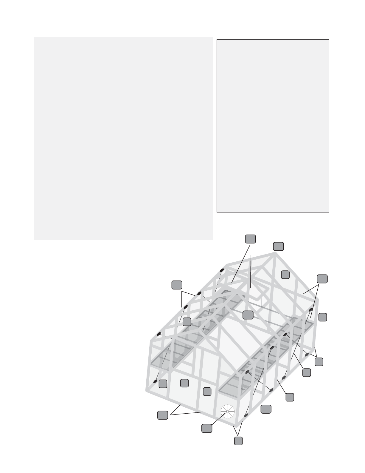
General Order of Assembly
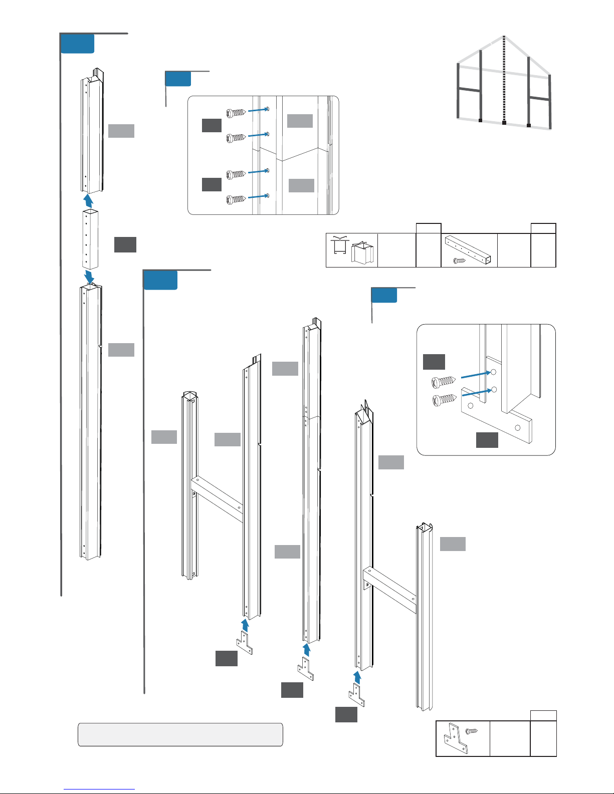
Step 1: Assemble Back
Step 2: Assemble Doors
Step 3: Assemble Front
Step 4: Assemble Sides
Step 5: Prepare Shelves
Step 6: Connect Sides to Back
Step 7: Connect Sides to Front
Step 8: Assemble and Connect Gables
Step 9: Brace Sides
Step 10: Assemble and Install Roof Vents
Step 11: Install Circular Vent
Step 12: Install Side and Roof Panels
Step 13: Weather Stripping
Step 14: Install Trim Plates
Step 15: Weather Strip and Hang Doors
Step 16: Secure to Ground
Step 17: Install Trays and Bin Holder
1
3
4
9
5
8
13
12
11
14
15 16
10
6
7
Safety Advice
The greenhouse must be positioned and xed on a at level
surface.
Dispose of all plastic bags safely. Keep them out of the reach
of small children.
Keep children and pets away from the assembly area until
the work is completed.
Always wear shoes, gloves and safety goggles when working.
In manufacturing all sharp edges and burs have been removed
but caution should still be taken when handling metal parts.
Do not lean against or push the greenhouse during assembly.
Take special care not to touch overhead power lines with the
aluminium proles.
Do not attempt to assemble the greenhouse in windy or wet
conditions.
Do not position your greenhouse in an area exposed to
excessive wind.
If using power tools or a step ladder always follow the
manufacturers safety instructions.
Hot items such as recently used grills, blowtorches etc. must
not be stored in the greenhouse.
Store the polycarbonate panels in a cool dark place like a
garage until you are ready to use them.
Make sure the greenhouse complies with local building codes.
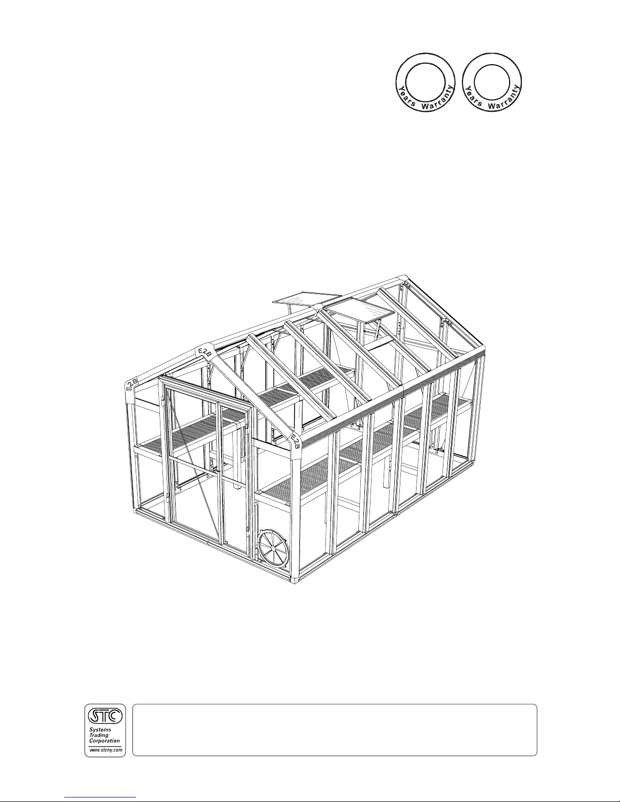
Introduction .........................................
Safety Advice .......................................
General Order of Assembly ............
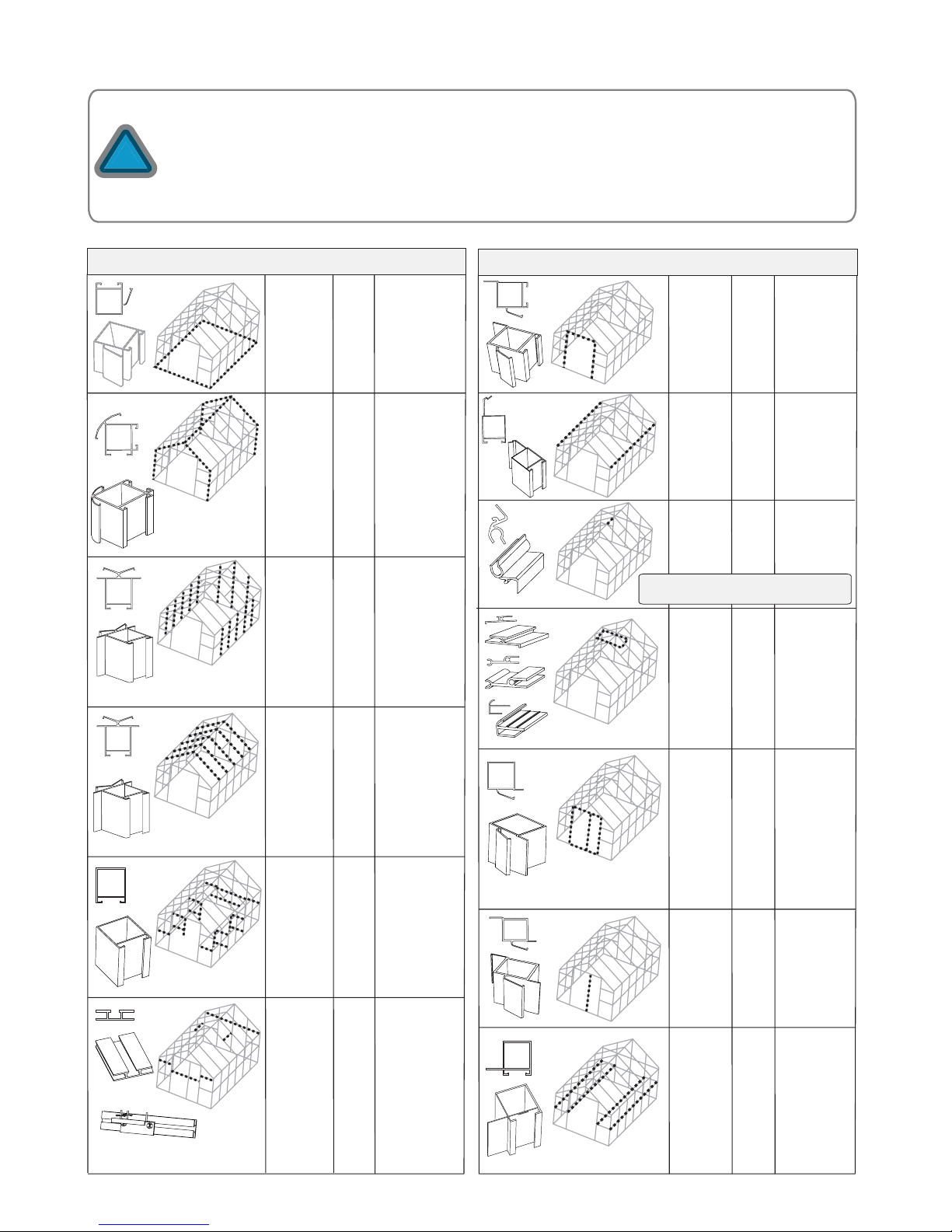
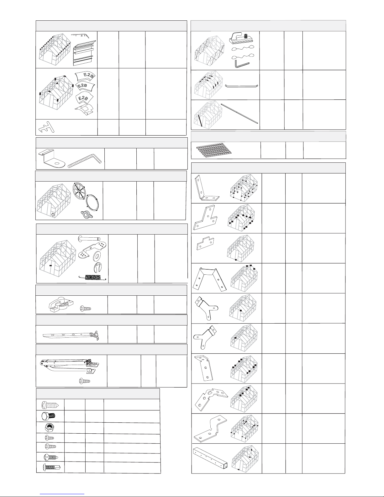
List of Parts ...........................................
Assemble Back ....................................
Assemble Doors ..................................
Assemble Front ..................................
Assemble Sides ...................................
Prepare Shelves ..................................
Connect Sides to Back ......................
Connect Sides to Front .....................
Assemble and Connect Gables ......
Brace Sides ............................................
Assemble and Install Roof Vents ...
Install Circular Vent ...........................
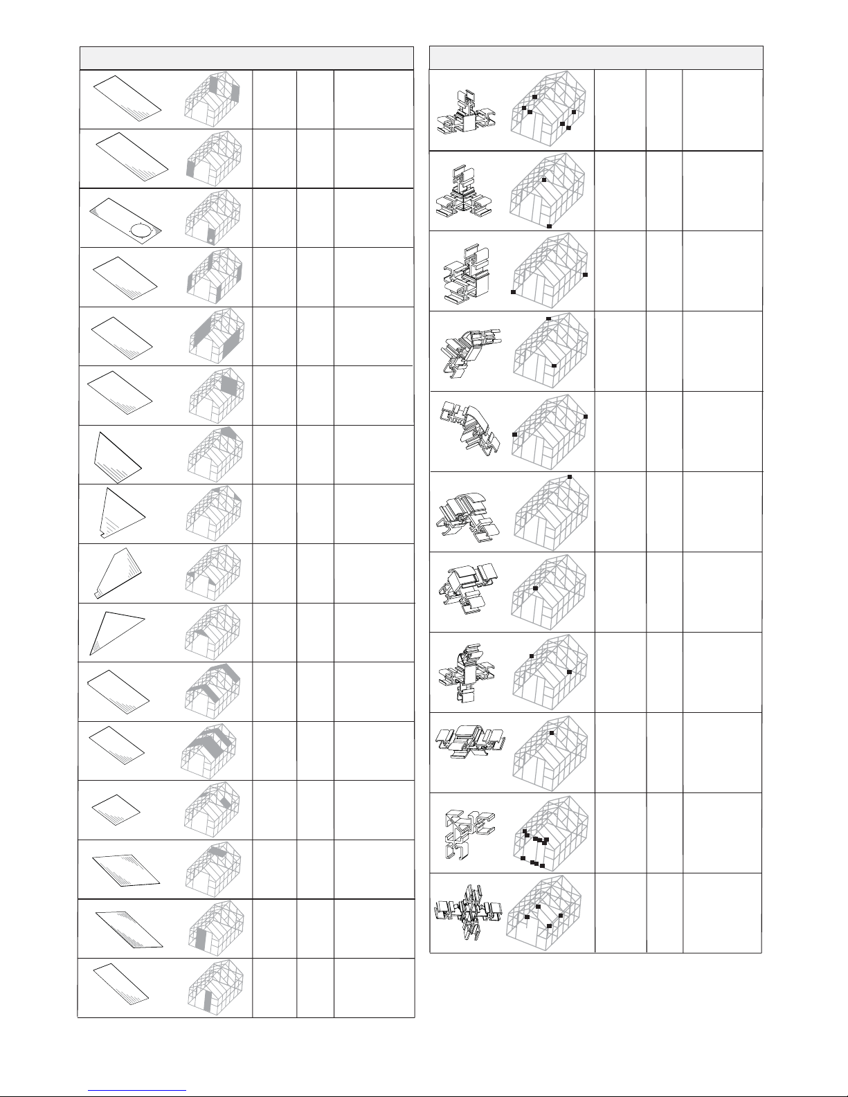
Install Side and Roof Panels ............
Install Weather Stripping ................
Install Trim Plates ................................
Weather Strip and Hang Doors ......
Secure to Ground ................................
Install Trays and Bin Holder .............
Table of Contents
2
2
17
2 of 56
www.stcny.com
1
2
2
3
6
15
19
27
33
34
36
39
43
45
49
50
51
52
54
55
56