Systium Technologies 555 User manual

SySTIUM®TECHNOLOGIES
Assembly Guide
Model 555

SySTIUM®TECHNOLOGIES MotherBoard ReadyTM System • MODEL 555
Radio Frequency Interference Notice (USA)
This equipment has been tested and found to comply with the limits for a Class B digital device, pursuant to Part 15 of
the FCC Rules. These limits are designed to provide reasonable protection against harmful interference in a residential
installation. This equipment generates, uses, and can radiate radio frequency energy and, if not installed and used in
accordance with the instructions, may cause harmful interference to radio communications. However, there is no
guarantee that interference will not occur in a particular installation. If this equipment does cause harmful interference to
radio or television reception, which can be determined by turning the equipment off and on, the user is encouraged to
try to correct the interference by one or more of the following measures:
•Reorient or relocate the receiving antenna.
•Increase the separation between the equipment and the receiver.
•Connect the equipment into an outlet on a circuit different from that to which the receiver is connected.
•Consult the dealer or an experienced radio/TV technician for help.
Any changes or modifications not expressly approved by the grantee of this device could void the user’s authority to
operate the equipment. The customer is responsible for ensuring compliance of the modified product.
Only peripherals (computer input/output devices, terminals, printers, etc.) that comply with FCC class B limits may be
attached to this computer product. Operation with noncompliant peripherals is likely to result in interference to radio and
TV reception.
All cables used to connect to peripherals must be shielded and grounded. Operation with cables, connected to
peripherals that are not shielded and grounded may result in interference to radio and TV reception.
Manufacturer: SySTIUM® Technologies, LLC
New Hope, MN 55428
763-537-3600
Contact: Customer Support
NOTE
If a Class A device is installed within this system; then the system is to be considered a Class A system. In this
configuration, operation of this equipment in a residential area is likely to cause harmful interference.
Radio Frequency Interference Notice (CDN)
This Class B digital apparatus complies with Canadian ICES-003:2004
Cet appareil numérique de Ia classe B est conforme a Ia norme NMB-003:2004 du Canada.
Declaration of the Manufacturer or Importer
This system is compliant with Low Voltage Directive 2006/95/EC using the standard EN 60950-
1:2006/A11:2009/A1:2010/A12:2011, (IEC 60950-1:2005 (2nd Edition); Am 1:2009).
This system is compliant with EU directive 2004/108/EC using the standards EN55022:2010 and EN55024:2010.
Disclaimer Statement
SySTIUM® Technologies makes no warranty of any kind with regard to this material, including, but not limited to, the
implied warranties of merchantability and fitness for a particular purpose. SySTIUM® Technologies assumes no
responsibility for any errors that may appear in this document. SySTIUM® Technologies makes no commitment to
update nor to keep current the information contained in this document. No part of this document may be copied or
reproduced in any form or by any means without prior written consent of SySTIUM® Technologies.
Third-party brands and trademarks are the property of their respective owners.

SySTIUM®TECHNOLOGIES MotherBoard ReadySM System • MODEL 555
Copyright © 2013, SySTIUM® Technologies, LLC
PN: 91609-00 Rev01
ASSEMBLY GUIDE
Assembly Safety Instructions
Assembly of a computer system using the Systium
Model 555 enclosure t shall be done only by technically
qualified personnel. Follow the instructions in the
document “Model 555 Maintaining Regulatory
Compliance” to meet and maintain the safety and
product regulatory compliance of this product when
assembling a computer system using this product.
WARNINGS
Read and adhere to all of these instructions and
instructions supplied with this assembly. Failure
to follow these instructions will result in voiding
the products regulatory compliance statements.
The procedures in this document assume familiarity
with the general terminology associated with personal
computers and with the safety practices and regulatory
compliance required for using and modifying electronic
equipment.
WARNINGS
TO PREVENT ACCESS TO HIGH
ELECTRICAL ENERGY PARTS, DO NOT
REMOVE THE COVERS WHILE THE
SYSTEM IS POWERED ON!
Do not open the power supply. The power supply
in this computer contains no user-serviceable
parts. To avoid personal injury or damage to
your equipment, refer repair or replacement of
the power supply to qualified technical personnel
only. All other areas and components of this
computer are considered user-accessible.
CAUTIONS
Electrostatic discharge (ESD) can damage disk
drives, add-in cards, and other components.
Follow the procedures described in this chapter
only at an ESD workstation. If such a station is
not available, you can provide some ESD
protection by wearing an anti-static wrist strap
and attaching it to a metal part of the chassis.
Add-in cards can be extremely sensitive to ESD
and always require careful handling. After
removing the card from its protective wrapper or
from the computer, place the card flat on a
grounded, static-free surface, component side
up. Use a conductive foam pad (f available, but
not the board wrapper Do not slide the board
over any surface.
For proper cooling and airflow, always close the chassis
before turning on the computer system. Operating the
computer system without the chassis closed can
damage system parts.
Before You Begin
1. Be sure to follow each procedure in the correct
order.
2. Set up an equipment log to record the computer’s
model and serial numbers, all installed options,
and other information about the computer. This
information must be saved as a record of the
product’s configuration and compliance with the
allowable configuration options.
3. We recommend that you use an anti-static wrist
strap and a conductive foam pad when working
on the computer.
4. You will need a Phillips (#1 and #2 bits)
screwdriver and Needle Nose Pliers.
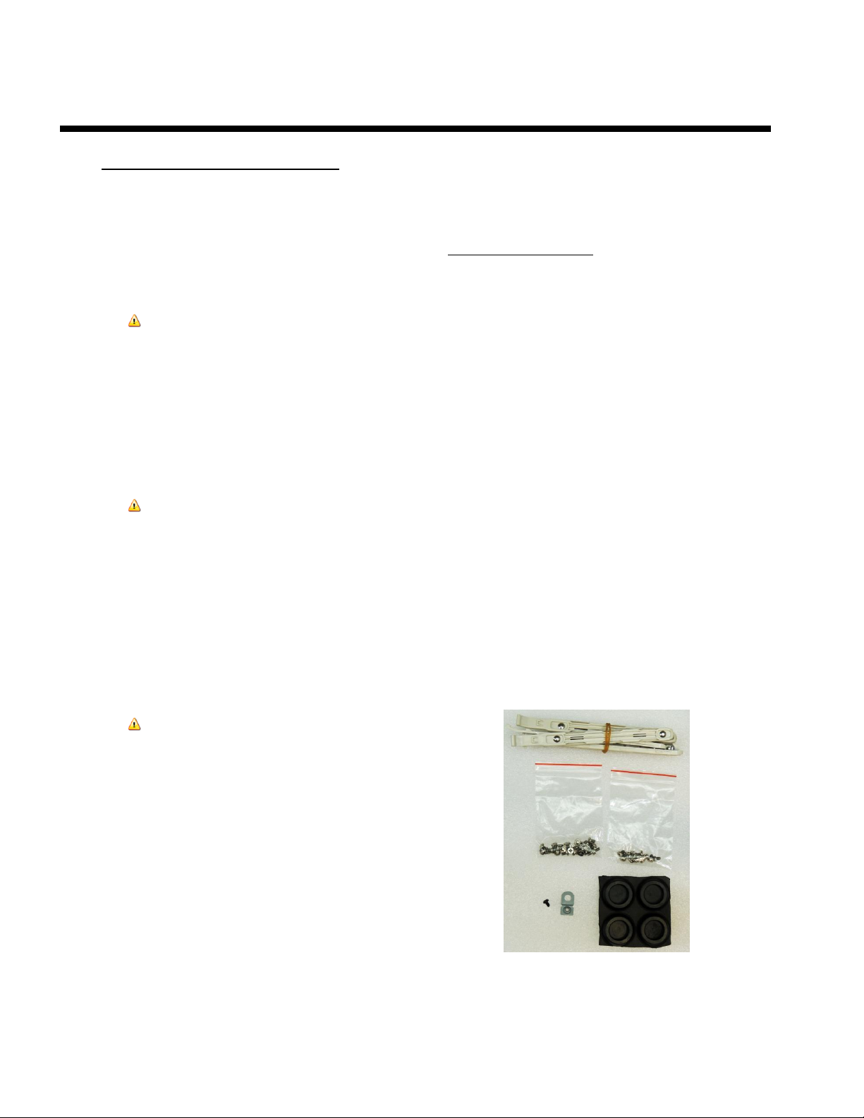
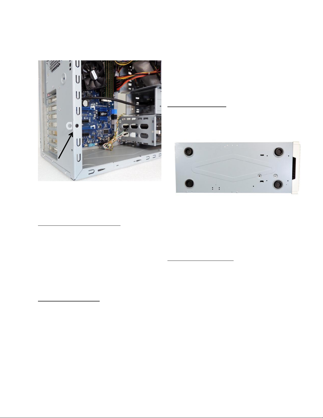
NOTE
The integration kit provides screws for the
following as shown in Figure 1:
• Six 3.5 peripheral mounting slides
• One lock tab and its associated .25” 6-32
Screw
• Eleven 6-32 Phillips Screws
• Six M3 Phillips screw
• Four Chassis Feet
FIGURE 1

SySTIUM®TECHNOLOGIES MotherBoard ReadySM System • MODEL 555
Copyright © 2013, SySTIUM® Technologies, LLC
PN: 91609-00 Rev01
Assembly Notes for Different
Motherboards
The Model 555 supports a number of different
motherboards. A number of the assembly step details
are different for each specific motherboard. This
manual describes the steps required to complete the
base system assembly task. Any steps or figures
specific to a particular motherboard are noted with a
reference to the assembly instructions specific to that
motherboard. If no other board instructions are present,
then the assembly step is consistent for all
motherboards.
NOTE
If the manual does not include information for your
specific motherboard check the Systium Technologies web
site www.Systium.com, support for updates to this manual.
Unpack the System
Systium Technologies offers MotherBoard Ready
products in two packaging configurations. The first is a
reusable “End-User” ready single package. The second
is a hi-volume bulk package. The instructions detailed
are for the single package. Any differences in
procedures between the single package and bulk
package are noted within each section. The integration
kits are the same for the single or bulk package
MotherBoard Ready Systems.
CAREFULLY UNPACK THE COMPUTER. Save the
box and packaging material for shipment to the
customer. If components are missing please contact
your supplier or Systium Technologies.
BULK PACKAGE
Please re-cycle the packaging when possible. None of
the bulk pack packaging is designed for reuse when
shipping to the end customer.
CONTENTS
The Model 555 MotherBoard Ready System product
contains the following:
•Model 555 Chassis with Power Supply
Installed
•North American Compliant Power Cord
•Integration Kit
• Quickstart Guide. (This manual must be
included in shipment to the End User.)
•Manual
Removing a Side Cover
1. Remove the plastic bag protecting the chassis.
Save the bag for shipping the assembled
computer.
2. Remove the two screws securing the
right cover (as viewed from the rear of the
chassis) to the chassis. Refer to Figure 2
above.
3. Using the handhold in the cover slide the
cover toward the rear of the chassis. The
cover should move approximately .5 inch.
Refer to Figure 3 above.
FIGURE 3
left
cover
screws
right
cover
screws
FIGURE 2

SySTIUM®TECHNOLOGIES MotherBoard ReadySM System • MODEL 555
Copyright © 2013, SySTIUM® Technologies, LLC
PN: 91609-00 Rev01
4. The cover will easily pull away from the frame.
Refer to Figure 4.
5. Place the cover to the side where it will not get
scratched or damaged before reassembly.
NOTE
The same steps are followed for the left cover. The left
cover only needs to be removed for installation of a
peripheral in the lower 5.25” bay. If the left cover is not
removed then care must be taken not to scratch or damage
the cover when assembling the system.
Removing the Front Bezel
The front bezel must be removed to install a 5.25” or
3.5” external peripheral.
1. Grasp the top front of the bezel with one hand.
Place the other hand and the chassis to hold it
in place. Refer to Figure 4
2. Carefully pull the front bezel away from the
chassis. There are 6 snap locks that hold the
bezel in place.
3. Place the bezel to the side where it will not get
scratched or damaged before reassembly.
Installing the I/O Shield
1. Locate the I/O shield supplied with the
motherboard.
2. Place the lower surface of the I/O shield in the
I/O opening in the rear of the chassis. Ensure
the I/O shield is fully inserted into the opening.
Refer to Figure 6
3. Carefully press the top surface of the I/O
shield into the I/O opening. Be careful to only
place pressure at the outer edges of the I/O
shield when pressing on the I/O shield. Check
that the I/O shield is fully inserted into the I/O
opening.
NOTE: Failure to properly install the I/O shield can result
in EMI leakage that will result in the computer system not
meeting the product's EMC compliance.
Installing the Motherboard
1. Specific motherboards may require the
installation of a screw-in standoff(s) in the
chassis base to mount the motherboard to.
The standoff(s) are included with the
integration kit.
2. Following the instructions supplied with the
motherboard, install the CPU and memory.
Ensure that the recommended ESD protection
guidelines are followed.
3. Place the motherboard on the mounting
supports. Carefully slide the motherboard
towards the rear of the chassis to engage the
motherboard connectors into the I/O shield
openings. Refer to the assembly instructions
for the motherboard being installed for a figure
of the correct installation of the motherboard
into the I/O shield.
FIGURE 4
FIGURE 5
FIGURE 6

SySTIUM®TECHNOLOGIES MotherBoard ReadySM System • MODEL 555
Copyright © 2013, SySTIUM® Technologies, LLC
PN: 91609-00 Rev01
4. Using the mounting screws supplied, mount
the motherboard to the chassis. Ensure that
the motherboard is fully inserted into the I/O
shield while being tightened into place. Check
that the fingers on the I/O shield are in contact
with the connectors.
NOTE: Failure to ensure the fingers are touching the
connectors can result in EMI leakage that will result in the
computer system not meeting the product's EMC
compliance.
5. The power supply supports the connection of
the fan monitor cable to one of the
motherboard fan connectors. Refer to the
assembly instructions for the specific
motherboard being installed for the correct
installation of the power supply fan monitor
cable.
NOTE: Connection of the power supply fan monitor cable
is optional. The cable can be left unconnected, placed
cleanly inside the chassis.
6. Connect the front panel connectors to the
motherboard. Refer to the motherboard
manual for the correct positions. Refer to
assembly instructions for the specific
motherboard being installed for a figure of the
correct installation of the front panel
connectors.
7. Connect the ATX and ATX-12V power
connectors to the motherboard. Refer to the
motherboard specific assembly instructions for
any additional motherboard power
connections.
Installing a PCI-E Video Adapter
(Optional)
If the motherboard does not support a built-in video
adapter or the built-in video adapter is not being used,
you must install a video adapter in the slot provided.
1. Refer to motherboard manual for the location
of the PCI-E video slot. Remove the screw
holding the I/O slot cover.
2. To completely remove the I/O slot cover, slide
the cover upwards and away from the back of
the chassis.
3. Refer to the video adapter manual for any
installation or configuration steps that need to
be completed before installing the adapter into
the chassis.
4. Install the video adapter. Refer to the
motherboard manual for any motherboard
specific installation instructions.
5. Secure the video adapter to the chassis by
installing the I/O cover screw removed in step
1.
Installing a I/O Adapter (Optional)
If an I/O adapter is part of the system configuration the
following instructions should be followed. If no I/O
adapter is to be installed, then this section can be
skipped.
1. Remove the screw holding the I/O slot cover
for the I/O slot to be used. Refer to Figure 8 for
the location of the I/O slot covers.
2. To completely remove the I/O slot cover, slide
the cover upwards and away from the back of
the chassis.
3. Refer to the I/O adapter manual for any
installation or configuration steps that need to
be completed before installing the I/O adapter
into the chassis.
4. Install the I/O adapter. Refer to the
motherboard manual for any motherboard
specific installation instructions. Refer to
Figure 8
FIGURE 7
PCI SLOTS

SySTIUM®TECHNOLOGIES MotherBoard ReadySM System • MODEL 555
Copyright © 2013, SySTIUM® Technologies, LLC
PN: 91609-00 Rev01
5. Secure the I/O adapter to the chassis by
installing the I/O cover screw removed in step
1.
Installing a 3.5” External Peripheral(s)
(Floppy, Front Panel I/O, USB Slots)
NOTE
The system must have one 3.5" external peripheral
installed. Failure to install a 3.5" external peripheral can
result in EMI leakage that will result in the computer
system not meeting the product's EMC compliance. A 3.5"
EMI shield is not supplied with the Model 555 and must be
ordered separately from Systium.
1. Refer to the peripheral's user manual for
instruction on peripheral configurations.
2. Position the peripheral in one of the two 3.5”
bays on the 555 lining up the peripheral
screws holes with the 555 slots.
3. Using the mounting screws supplied with the
peripheral –secure the peripheral in place.
Refer to figure 9.
NOTE
If a second 3.5" external peripheral is installed you must
first remove the EMI shield built in to the chassis. The EMI
shield can be removed by inserting a screwdriver into the
hook in the EMI shield.
The shield can then be rotated carefully to break the
mounting slips.
Completely remove the EMI shield form the chassis and
dispose of it properly.
Installing 3.5” Internal Peripheral(s)
1. Position the mounting rails on the side of the
peripheral (HDD) as shown in Figure 10.
2. Press the mounting rail in the peripheral
mounting screw holes. Install the second
mounting rail on the opposite side of the 3.5”
peripheral. Refer to Figure 11.
FIGURE 9
FIGURE 8
FIGURE 10
FIGURE 11

SySTIUM®TECHNOLOGIES MotherBoard ReadySM System • MODEL 555
Copyright © 2013, SySTIUM® Technologies, LLC
PN: 91609-00 Rev01
3. Line up the mounting rails with the
corresponding guides in the 3 bay internal
peripheral bay of the chassis. Insert the
peripheral into the chassis until the front tabs
lock to the side of the chassis. Refer to Figure
12
Re-install Front Bezel
1. It is recommended to re-install the front bezel
prior to placing the 5.25” peripherals so that
aligning the front of the optical drives with the
bezel front is easier and more precise.
2. Remove any plastic filler panels required for
access to installed external peripherals.
3. Position the 6 snap locks with their
corresponding holes. Carefully snap the front
bezel back into place. Refer to Figure 13.
Installing 5.25” External Peripheral(s)
(All Bays)
1. Refer to the peripheral's user manual for
specific instructions to configure the peripheral
2. Position the peripheral in the slot lining up the
front of the peripheral with the bezel front.
3. Secure the 5.25” external peripheral to the
chassis with the supplied mounting screws.
Refer to Figure 14
NOTE
The system must have one 5.25" external peripheral
installed or an
EMI shield must be installed. Failure to install a 5.25"
external peripheral or EMI shield can result in EMI
leakage that will result in the computer system not meeting
the product's EMC compliance. A 5.25" EMI shield is not
supplied with the Model 545 and must be ordered separately
from Systium.
Install Cover Lock Tab
NOTE
The Model 555 utilizes a power supply with an Energy
Hazard on the 12V circuit. Compliance with CE requires
installation of the cover lock tab and a lock or the use of the
6-32 TORX screw to secure the top cover.
1. Locate the locking tab and mounting screw in
the accessory package.
2. Position the locking tab in the notch on the
right rear edge of the chassis. Secure the
locking tab to the chassis using the screw
supplied. Refer to Figure 15.
FIGURE 12
FIGURE 13
FIGURE 14

SySTIUM®TECHNOLOGIES MotherBoard ReadySM System • MODEL 555
Copyright © 2013, SySTIUM® Technologies, LLC
PN: 91609-00 Rev01
Connect Peripheral Cables
1. Connect the cables supplied with the motherboard
and/or installed peripheral devices. Care should be
given to ensure the cables do not block airflow within
the chassis and are routed cleanly to facilitate future
system maintenance. Refer to assembly instructions for
the specific motherboard being installed for a figure
showing an example of cable routing.
2. Connect the power cables to the peripherals.
Install Side Cover(s)
NOTE
Before installing the right side cover please check that all
cables are connected and no tools, screws or accessories are
left inside the chassis.
1. Position the lower groove in the side cover to
fit onto the lower and upper edges of the
chassis.
2. Close the side cover so as to be flush with the
chassis.
3. Slide the cover towards the front of the
chassis. Ensure that all the mounting clips on
the cover are fully engaged with the chassis. If
the optional locking tab is installed, ensure that
the tab is inserted into the slot in the cover.
4. Secure the cover to the chassis with the two
screws removed when the cover was originally
removed.
Install Chassis Feet
1. Remove the chassis feet and install in proper
location on the bottom of the chassis as shown
in Figure 16.
NOTE
To install the left cover the same steps are followed except
there is no locking tab on the left side of the chassis.
Power up the System
1. Connect the keyboard, mouse, monitor and
any other required peripheral for the correct
operation of the computer. Refer to the Quick
Start section in this manual for assistance in
connecting the peripherals to the computer.
2. Turn on the computer by pressing the power
switch on the front panel. Refer to the Quick
Start Section of this manual for more
information.
3. Verify the operation of the POWER ON
indicator on the front panel. The LED should
glow constantly when the computer is turned
on. Verify that the floppy LED turns on when
the system resets the floppy drive during the
POST. Verify the operation of the hard drive
LED on the front panel. The LED should turn
on when the POST resets the hard drive or
attempts to boot the computer. Correct any
problems detected during the initial power up
phase.
FIGURE 15
FIGURE 16

SySTIUM®TECHNOLOGIES MotherBoard ReadySM System • MODEL 555
Copyright © 2013, SySTIUM® Technologies, LLC
PN: 91609-00 Rev01
4. Test the complete operation of the computer
using a known good computer functional test
program such as Intel’s Test view. Install any
required operating system or application
software.
NOTE
The computer must have all the required warning and
information lights functioning before shipping to the end
user.
5. Disconnect the computer from the peripherals used
during the testing phase. Package the computer using
the original packaging. (Single Pack Only).
NOTE
You must include the End User Quick
Start manual in the shipment to the
customer to maintain Regulatory
Compliance.
NOTE
If the computer was assembled from a bulk pack
Motherboard Ready product the computer must be
packaged in a Single pack box or similar packaging before
being shipped to the end user.
Table of contents
Other Systium Technologies Computer Accessories manuals