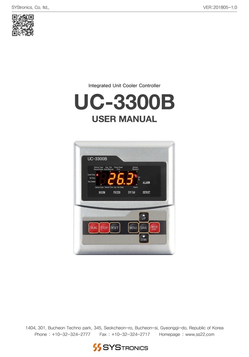
SYStronics AC-3301L User manual

AC-3301L MANUAL
1
AC-3301L
USER MANUAL
Integrated Air Conditioner Controller
VER 201806-1.0SYStronics. Co. ltd.,
1404, 301, Bucheon Techno park, 345, Seokcheon-ro, Bucheon-si, Gyeonggi-do, Republic of Korea
Phone : +10-32-324-2777 Fax : +10-32-324-2717 Homepage : www.ss22.com

AC-3301L MANUAL
2
Be sure to read and ensure that your safety precautions are used to protect your safety and prevent property
damage. We shall not accept any liability for any loss caused by the use or carelessness caused by the use
or handling of this manual.
Warning
If this product is not intended as a safety device, use a double safety device for fear of accidents, damage of
critical peripheral equipment, and equipment that is feared to cause extensive property damage.
Safety instructions
1. Be sure to check the equipment after disconnecting mains.
2. Do not disassemble and repair this product ; it is not possible to manufacture any product.
3. Do not spray water directly or clean it with benzene, jazzy, or alcohol.
Notes on the environment
Do not install this product in the following locations and environments :
1. Places directly exposed to mechanical vibration or shock
2. Places exposed to corrosive gases or combustible gases
3. Position directly exposed directly to direct sunlight
4. Places affected by electromagnetic waves
5. Places where high temperature or humidity is high (sites with over 85 % of ambient humidity)
6. Places where dust and salt are plentiful
Precautions on installation
1. Make sure that the installation work is related to the installation or qualified personnel only.
2. Do not place any device or wiring that caused noise (NOISE) near the product.
3. Avoid near heating apparatus.
4. Disconnect all appliances (OFF) after disconnecting them from the wiring.
5. Do not work with wet hands. Risk of electric shock.
6. Install and use the method described in the User Manual as instructed in the Instructions for Use.
7. Do not turn on (power on) prior to the connection between the unit of manufacture of this unit.
8. Do not use any load exceeding the opening and closing capacity of the output contacts.
Immunity condition
1. In addition to the contents set forth herein, no warranties and responsibilities shall be made regarding this
product.
2. Whether or not this product is likely to be unforeseen defects and natural disasters due to the use of this
product, the user or the third person We shall not be held liable for any indirect damage.
Precautions

AC-3301L MANUAL
3
Product Overview
This controller is dedicated to the cooling and heating system, and has various functions such as
cooling and heating, power failure recovery, temperature deviation and compensation, comp delay and alarm
return setting. It can be linked with remote management system using RS-485 communication. It is
able to express the operation and alarm status of controller through LCD liquid crystal display. And the
display and I / O board are integrated and easy to install and manage.
·All-in-one controllers for cooling and heating
·Temperature deviation, compensation, power failure return function
·Comp delay and alarm return setting function
·Remote control via RS-485 communication

AC-3301L MANUAL
4
Product Component
Sensor Component
Normal Type
NTC Sensor
(1EA / SCTS-01)
Basic Type
Standard Sensor
Advanced Type
NTC Sensor
(1EA / SCTS-02)
Selectable
Option Sensor
Well Type NTC
Sensor
(1EA / SCTS-04)
Selectable Option
Sensor
(Choose one of the three sensor)
Unit Cooler Controller
(1EA / AC-3301L)
Guide
(1EA)
Guide Screw
(2EA / N3)

AC-3301L MANUAL
5
Product Specification
Integrated Unit Cooler Controller (AC-3301L)
Input power 100 ~ 220VAC, 50/60Hz
Output voltage 100 ~ 220VAC, 50/60Hz (Main fuse 3A / 250V)
Output contact capacity 250VAC, 5A (Relay output)
Input port 3 Port (Non powered contact)
Output port 6 Port (Input power output)
Sensor port 1 Port (NTC : 10K at 25℃ ±1%)
Comms. port 2 Port (RS-485)
Operation temp. -10 ~ 60℃ (Non condensing)
Operation humi. 5 ~ 90% (Non condensing)
Storage temp. -20 ~ 60℃ (Non condensing)
Body weight 358g
Guide weight 63g
Normal Type Cable Sensor (SCTS-01 / Basic type standard sensor)
Temperature Range -45 ~ 80℃
Accuracy NTC : 10K at 25℃ ±1%
Sensor Weight 58g (Cable basic 3M standard)
Advanced Type NTC Sensor (SCTS-02 / Selectable type option sensor)
Temperature Range -45 ~ 105℃
Accuracy NTC : 10K at 25℃ ±0.5℃
Sensor Weight 37.5g (Cable basic 3M standard)
Well Type NTC Sensor (SCTS-04 / Selectable type option sensor)
Temperature Range -45 ~ 80℃
Accuracy NTC : 10K at 25℃ ±1%
Sensor Weight 84g (Cable basic 3M standard)

AC-3301L MANUAL
6
Product Dimension
Top view
Front view
Guide Dimension (Unit : mm)
Controller Dimension (Unit : mm)
Side view
Top view
Front view Side view

AC-3301L MANUAL
7
Well Type NTC Sensor (SCTS-04 / Selectable type option sensor)
Temperature Range -45 ~ 80℃
Accuracy NTC : 10K at 25℃ ±1%
Sensor Weight 84g (Cable Basic 3M standard)
Advanced Type Cable Sensor (SCTS-02 / Selectable type option sensor)
Temperature Range -45 ~ 105℃
Accuracy NTC : 10K at 25℃ ±0.5℃
Sensor Weight 37.5g (Cable Basic 3M standard)
Normal Type Cable Sensor (SCTS-01 / Basic type standard sensor)
Temperature Range -45 ~ 80℃
Accuracy NTC : 10K at 25℃ ±1%
Sensor Weight 58g (Cable Basic 3M standard)
Sensor Dimension

AC-3301L MANUAL
8
Product Installation Method
1. Remove the two terminal blocks located on the left side of the controller for mounting on perforated panels
or equipment.
2. Punched holes (W111.0 x H126.0 / mm) to fit the panel or equipment, and then push the controller in
place to fix it.

AC-3301L MANUAL
9
Product Installation Method
3. Align the guide provided with the product with the groove on the back side of the controller, and fix the
controller securely so that it does not move, using the guide fixing screws (2EA / N3).
4. Connect the terminal block to the left side of the controller and proceed with wiring.

AC-3301L MANUAL
10
Product Wiring Method
Wiring Precautions
1. Check the polarity of the wiring before connecting the wiring correctly.
2. To avoid malfunction due to noise from the product, avoid the use of the same conduit or the same duct
for the wiring of high-voltage lines and power lines and sensors.
Wiring Reference Diagram

AC-3301L MANUAL
11
Operating Function
Name Image Main screen Setting screen
Power
button
Operation run / stop
(Press for 2 seconds) ·
Alarm stop
button
Check alarm history (Press short)
Release alarm (Press short) ·
Setting
button
Go to general setting (Press short)
Return to main screen (Press short)
Go to parameter setting
(Press for 5 seconds)
Return to main screen
(Press short)
Save button
·Save changed setting value
(Press short)
Up button ·Go to top menu
(Press short / long)
Down button
·Go to bottom menu
(Press short / long)
Decrease
button
Go to backlight time setting menu
(Press for 3 seconds)
Decrease setting value
(Press short / long)
Increase
button
Increase setting value
(Press short / long)
Up button
Save button
Increase button
Decrease button Down button
Setting buttonPower button
Alarm stop button

AC-3301L MANUAL
12
Display Flow Chart
S.TEMPC.TEMP
25.0℃25.0℃
Air Conditioner
Controller
S.TEMPC.TEMP
25.0℃25.0℃
1)Test Mode
2)Preferences
3)Integration Time
4)Alarm Status
< Test Mode >
1)FAN TEST
2)COMP1 TEST
3)COMP2 TEST
< Preferences >
1)EQUIP NO.: 1
2)POWER REC: 10s
3)STOP DELAY: 90s
< Integration Time >
COMP1 0
COMP2 0
HEATER1 0
< Alarm Status >
1)FAN ALARM
2)TEMP SENSOR
< Backlight Setting >
Backlight: ON
1)S.TEMP: 24.0℃
2)COOLING DIFF:1.0℃
< Operation Status >
FAN
3sec
Main ScreenBacklight Setting Screen General Setting Screen
Standby Screen
Parameter Setting Screen
Test Mode Screen
Operation Status Screen
Setting Screen Integration Time Screen Alarm Status Screen
2sec2sec
3sec

AC-3301L MANUAL
13
< Integration Time >
COMP1 0
COMP2 0
HEATER1 0
< Operation Status >
FAN
COMP1 COMP2
HEATER1 HEATER2
< Alarm Status >
1)FAN ALARM
2)TEMP SENSOR
Display Function
S.TEMPC.TEMP
25.0℃25.0℃
Main Screen
Displays the current temperature and set temperature, animation and alarm status such as cooling, heating.
1 2 3 4
1 2 3 4
Fan on
Fan off
Cooling on
Cooling off
Heating on
Heating off
Alarm occur
Alarm not occur
Operation Status Screen
This screen allows you to check the current operation status such as blowing, cooling and heating operation.
Alarm Status Screen
Up to 8 alarms are displayed, and the most recent alarms are displayed at the top. If the number exceeds 8,
the oldest alarm is automatically deleted.
Alarm List Screen
Displays the history of the current alarm. When three or more alarms are displayed, a new alarm is show up only
when the alarm history is deleted.
Integration Time Screen
It is a function to accumulate total cumulative time of cooling and heating. And the unit is one hour.
Press the key for 3 seconds to delete a single item.
< Alarm List >
DELETE CANCEL
1)FAN ALARM
2)TEMP SENSOR
Press the key for clear the entire alarm history.
Press the key for return to main screen.

AC-3301L MANUAL
14
Name Image Setting screen Name Image Setting screen
Up button
Move to top menu
(Press short: Move slowly)
(Press long : Move quickly)
Down
button
Move to bottom menu
(Press short: Move slowly)
(Press long : Move quickly)
Increase
button
Increase setting value
(Press short: Change slowly)
(Press
long : Change
quickly)
Decrease
button
Decrease setting value
(Press short: Change slowly)
(Press
long : Change
quickly)
Save
button
Save setting value
(Press short)
Setting
button
Cancel setting value
(Press short)
Setting Details Description
Item
Set. range
Initial value
Contents
Set Temp
1.0 ~
75.0℃24.0℃
Set the control temperature of the
air conditioner.
Cooling
Diff
0.1 ~
5.0℃1.0℃
Set the operation and stop deviation of cooling operation by the cooling
deviation temperature for set temperature.
(Current temperature ≥(Setting temperature + cooling variation)
(Setting temperature : 15℃ / Cooling variation : In the case of 1℃, cooling
operation ON when current temperature is more 16℃cooling operation when
current temperature is less 15℃OFF.)
Heating
Diff
0.1 ~
5.0℃1.0℃
Set the heating operation for temperature compensation when the
temperature of the room drops due to overcooling.
(Current temperature ≤ (Setting temperature –heating variation)
(Setting temperature : 15℃ / heating variation : In the case of 1℃, heating
operation ON when current temperature is less 14℃ heating operation when
current temperature is more 15℃ OFF)
General Setting
Setting Operation

AC-3301L MANUAL
15
Setting Details Description
Item
Set. range
Initial value
Contents
Equip No
No.1
~ 99 No.1 When
remote sensing control function is used, device number is set and
device address is given.
Power
Rec
1 ~
240sec 10sec
It is a function to set the delay time until power failure and operation
restart.
Applying the power failure recovery time to several equipments prevents the
overload when restart after power failure.
Stop
Delay
1 ~
240sec 90sec
This function sets the blower stop delay time when stopping during
operation.
Comp
Alarm
1 ~
240sec 180sec
It is the function to set the delay time in the cooler alarm.
H.Temp
Alarm
1 ~
85
℃
40℃
A function that protects the equipment by generating an alarm when the
temperature rises above the average temperature.
High temperature alarm = equipment temperature ≤ high temperature alarm.
Cool.
STEP 1 / 2 2
This function sets the cooling step.
Heat.
STEP 1 / 2 2
This function sets the heating step.
Temp
Cali
-10 ~
10℃0.0℃
The temperature value is corrected when the actual temperature differs
from the actual temperature value inside the room.
If the room temperature is 20.0℃and the detected temperature is 18℃,
change the setting value to 2.0℃, and the current temperature value of the
monitor is expressed as 20.0℃.
Cool.
Delay
1 ~
240sec 5sec
This function sets the delay time from when the fan is output to when the
comp output is activated in the cooling condition.
Heat.
Delay
1 ~
240sec 10sec
This function sets the delay time from when the fan is output to when the
heater output is activated in the heating condition.
Heating
Not
use
/
Use Not use
This function sets whether to use heating operation.
Comp
Contact
A / B
contact
B contact
Set
the input contact of the compressor input after the compressor output
turns ON during cooling operation.
Comp
Delay
1 ~
240sec 30sec
This function sets the compressor delay time from when the compressor
is stopped to when it starts.
Comp
Alarm
Reset
Auto /
Manual Auto
This function sets the return method after the alarm.
Parameter Setting

AC-3301L MANUAL
16
Alarm Contents
Item Contents Solution
Comp
Alarm
It will occur if the contact does not come on
even after the comp alarm has run.
Confirm the contact of the compressor.
Check the equipment status of the Comp.
Fan
Alarm
It occurs when the contact point does not
come in for 5 seconds after blower output.
Check blower contacts.
Check the equipment status of the blower.
H.Temp
Alarm
Occurs when the current temperature is higher
than the high temperature alarm setting
temperature.
Check the high temperature alarm temperature.
Understand the temperature rise.
Temp
Sensor Occurs when sensor is open or shorted. Check the sensor connection.

AC-3301L MANUAL
17
The Service Guide is to protect the safety of the user and prevent property damage, so please read it carefully
and use it correctly. Please note that the warranty service does not apply to any case where the product is
used or handled arbitrarily without complying with the instructions specified in this Service Guide or manuals.
Use the product according to the specified method.
Regarding controller problems
Before submitting a service request, be sure to first read the details concerning the alarms or troubleshooting
checklist in the product manual of the corresponding model and follow the directions accordingly. The user
manual contains the troubleshooting procedure for the alarms and errors occurred to the controller.
What if the measures taken still don`t work?
Record the corresponding alarm or symptoms by taking a picture or video, and contact the equipment
manufacturer or supplier first. If this still doesn't resolve the problem, contact Systronics.
Service Charge
The warranty period for Systronics products is 1 year after purchase. (Warranty period for humidifier parts is
4,000 hours of operation time.) To ensure use of the product in a mint condition for a long period of time, be
sure to familiarize yourself with the precautions and instructions specified in the manual. For more information
on the service, refer to the product warranty statement in the user manual.
1. Please note that any problem/failure caused by the customer's inadvertent, unskilled handling and/or
negligence is not and will not be eligible for our warranty service.
2. This warranty service expires after 1 year of purchase. From that point on, your service request will be
charged for repairs or visits by our engineer.
3. Warranty service is not applicable to any failures caused by natural disasters (e.g., fire, flood, lightning, etc.).
Refund Policy
1. If you choose to return the product after 14 days have passed upon purchasing the product,you will have
to pay a refund fee even if you haven't used it.
2. Your refund request will be refused even when the request is made before 14 days pass upon purchasing
the product if you have installed or used the product.
Purchase Tip for Warranty Service
1. Before buying the product for warranty service, please listen carefully to the explanations offered by
Systronics and make a decision accordingly.
2. In principle, Systronics transacts with corporate clients. Therefore, restrictions may apply to the users at the
worksite who want to buy our product.
3. Let us know the information of the controller installed at the site (e.g., production no., program name,
Shipping date) through submission of an image or message form to quicken the order process.
Service Guide

AC-3301L MANUAL
18
Electronic control equipment has different operating characteristics from electromechanical equipment. Safety
instructions for the application, installation and maintenance of the electronic control unit, important differences
between the electrical and electronic control unit and the electric machine, and contents of the use for the
electric control unit. Due to these differences and the various uses of electronic equipment, the person
responsible for the application of this equipment must use and install this equipment only within the permitted
scope of application.
Overview of electrical noise control
Electrical noise can be caused by normal operation of components or components of the system due to
voltage spikes. The conduction mechanism may interfere with the operation of parts or elements of other
systems (noise interference), resulting in malfunction.
Generate noise source
1. Mechanically switched inductive loads generate strong noise intermittently. (MC, MCCB, etc.)
2. PWM drive power output generates severe continuous noise.
3. Switch mode DC power supply (SMPS) may continue to generate noise.
4. Noise source may occur due to contact switching.
Among the causes of the above noise sources, the noise that the system manufacturer can reduce is only
the contact switching noise.
Conduction noise
Electrical noise interferes with the normal operation of the equipment. In the case of electrical noise
conduction, noise may be directly conducted by the system power wiring, and may be emitted to the outside
through the wiring of the industrial control device (inverter).
ACㆍDC power cable installation
For AC·DC power installation, it is recommended to use junction, isolation, shielding and filter for power
supply and related wiring.
Motor power cable installation
If possible, do not extend the motor power cable. In principle, the cable between the drive and the motor can
not be used in extended connection. The universal reason for changing (extending) cables in the middle is
for applications that require flexible cables. Observe the following guidelines when handling the remaining
cables.
1. Do not detect different types of cables together. A transformer which is valid in HF is formed.
2. Cable length should be cut to fit the application.
3. If you can not cut the remaining cable, please arrange it in '8' or 'S' form. Never roll it round.
Precautions
Good example Good example Incorrect example

AC-3301L MANUAL
19
Cable shield treatment
The cables that require shielding are those that are driven by the inverter and special motors. We
recommend using a shielded cable as shown in the figure below where there is a lot of noise or precise
signal is required.
Precautions
Prepare for shielding Shield electrical wiring
Duct section separation
You should classify it as noise sources and noise interference rather than using convenience or clean wiring
as a reference. Regarding Noise of Cable Wiring Noise is judged to be a color line as ducts of a wiring which
is judged to be a clean signal line by using a "gray" line duct and ducts of a noise generating wiring by using
a duct of a "black" line This helps the wiring technician to isolate and manage the cables correctly.
Isolation work for panel cable noise
1. It is possible to install close to the line where the noise is generated and the line where the noise is
generated by placing a plated steel barrier.
2. If you need a lot of noisy power in area A, it is recommended to use shield cable through area B line.
3. As in the case of a cable consisting of A-zone horizontal line, it is necessary to avoid loops because
loops are formed centering on control microcomputer (loops cause high frequency of RF characteristic).
4. There must be no ground potential difference between the distributor panel and the main panel.
Connecting as much wire as possible helps to bring the ground potential close to 0V)
5. If possible, ground the shield at the panel entrance, as data and communication cables may contain noise
in the shield. Also, the data / communication cable and the power cable must be isolated and installed.
Noise Generating
Duct
Noise Free Duct
Plated Steel
Barrier
PWM /
DRIVER MC
PWM /
MOTOR MC
Noise Filter
PLC MC
Controller
Relay
Output
Terminal
Block
Power
Terminal
Block
Trans /
Power
A sectionB section

AC-3301L MANUAL
20
Isolation operation for cable noise
Isolation operation for cable noiseThe wiring of the microcomputer input / output wiring and the AC input
terminal must be separated from each other to prevent noise from occurring.
Precautions
The noise filter of the AC input terminal of the microcomputer must be separated from the input / output wiring
of the noise filter (the noise filter function is seriously degraded when integrated wiring is installed), and the
output terminal should be connected to the nearest position to the microcomputer.
Contact noise suppression method
MC's contactor coil, relay coil, transformer circuit, solenoid coil, cabinet Fluorescent lamp, etc. can be reduced
by applying a noise suppressing capacitor. Contact noise for an AC circuit controlled by a switch such as a
contactor coil or a relay coil requires an RC suppressor circuit at either the coil's positive or negative terminal
or an equivalent snubber capacitor. Generally 100Ωand 0.1Uf are connected in series, but it needs to be
adjusted according to the load power.
How to Identify the Source of the Noise Source
This is an oscilloscope-based measurement of noise peak inductance, as a method of directly measuring
noise in the field.
1. Induced peaks are short and the amplitude varies greatly with time, which is often difficult to measure.
2. On the oscilloscope, set the time axis to 1us /div and set the trigger to capture the peak.
3. Slowly increase the trigger level until triggering stops to measure the maximum peak voltage displayed.
4. Connect the probe grounding clip of the oscilloscope to the probe tip to form a small loop.
5. In the indirect measurement of the cable, the loop probe antenna is sensitive to the direction, so you
must measure the position by capturing the maximum value and fixing the probe.
Incorrect example Good example
Good example Good example
Incorrect Good
AC input terminal wiring Input / output signal AC input terminal wiring Input / output signal
Table of contents
Other SYStronics Controllers manuals
Popular Controllers manuals by other brands

Balmar
Balmar ARS-5 Installation and operation manual

Sheldon
Sheldon Watlow EZ-Zone Programming guide

Eaton
Eaton Cutler-Hammer Easy-Start ES Series instruction manual

Revolution Electronics
Revolution Electronics 12003 Installation instructions manual

Desoutter
Desoutter CVI3 Series Installation and upgrades

Contemporary Research
Contemporary Research ICA-FT6 product manual