SyxthSense DCPA80BC User manual

Product Sheet
TH6.20
Thermostat Type
DCPA80BC
Online Store: www.syxthsense.com
Enquiries: T: 0870 20 80 100 F: 0870 20 80 200 PS TH6.20 – 1/8
DCPA80BC Wireless Digital Chronostat
Model Types Model Description
DCPA80BC DCPA80BC Wireless Digital Chronostat
Technical Data Power supply 2 x 1.5V= alkaline batteries AAA type
Batteries duration ~ 1 year
Regulation range Comfort: 10°C .. 30°C
Economy: 10°C .. 30°C
Temperature Sampling Approx. every 3 minutes
Differential 0.2°C (asymmetric.: example. 20.0°C off 19.8°C on - heating mode -
20.0°C off 20.2°C on - cooling mode - )
Sensor type NTC 100k @ 25°C internal
Accuracy ± 1°C
Resolution Readout: 0.1°C; Set-point: 0.2°C
Output power (ERP) 10dBm max
Modulation type AM (ASK)
Antenna type: Internal
Max. distance from
receiver
30 m indoor (depending on the environment)
Storage Temperature -10°C .. +50°C
Operating Temperature 0°C .. 40°C
Protection Class IP30
Humidity Limits 20% .. 80% rH (non condensing)
Enclosure Material: ABS V0 self-extinguishing
Colour Cover: Signal white (RAL 9003)
Base color: Anthracite grey (RAL 7016)
Agency Compliance EEC 89/336, 73/23, 93/68, 99/05
Size 133W x 87H x 32D mm
This electronic chronostat is suitable for a reliable and accurate
temperature regulation in commercial and industrial premises as well as
in home installations. Its main feature is the capability of operation
without any wire connection: the commands are issued to the receiving
unit via radio signals, making this product extremely easy and
economical to install especially where no existing electrical wires are
available. The chronostat has built in comprehensive 7 day programming
capability that assures flexibility to both heating and cooling applications.
FEATURES
•Completely wireless chronostat 868.35 MHz band
•Unique version: both Daily and Weekly
•Two batteries AA type power supply
•Two levels room temperature regulation: Comfort and Economy
•Guided programming
•'Heating' or 'Cooling' mode with front panel selection
•Off position with adjustable antifreeze function
•Room temperature or current time readout
•Fixing with distance between holes 60 mm or 83 mm (3 mod.
junction boxes)

SyxthSense Ltd
Online Store: www.syxthsense.com Copyright ©2004 SyxthSense Ltd – 07/2004
Enquiries: T: 0870 20 80 100 F: 0870 20 80 200 PS TH6.20 – 2/8
Display Operation
At first operation insert the batteries respecting the polarity and perform a reset of the chronostat with
a small tip through the hole (7) Fig. 2.
Six buttons are present under the plastic door covering the batteries:
programming
day, hour & minutes regulation
confirmation (5)
forward (4)
back (6)
accessible through hole (7) for internal circuit and program test
Three buttons are on the front, close to the display:
Manual Temperature/Time O/Off

SyxthSense Ltd
Online Store: www.syxthsense.com Copyright ©2004 SyxthSense Ltd – 07/2004
Enquiries: T: 0870 20 80 100 F: 0870 20 80 200 PS TH6.20 – 3/8
Radio System Set-Up The chronostat turns-on or turns-off a relay in the receiving unit (receiver) by a radio link. Before
installing the chronostat in the desired position, it is necessary to test if the receiving unit correctly
receives its radio signals. To do this the chronostat must be turned-on in the “Test” mode. The
operation is described in the following.
Open the thermostat box removing the plastic back, use a small screwdriver, place it between the
back panel and the chronostat’s body as shown in (9) Fig. 10 then apply a slight pressure.
In Fig. 11 is visible the appliance’s internal layout. Set the appropriate address in the dip-switches
(11), the address is split in two parts, “family” and “device”. The family address must match the family
address set in the receiver unit, the device address must match one device address of one output
channel of the receiver. Take into account that different thermostats used with the same receiving
unit must operate with different device addresses to avoid data collision and malfunction. See
receiver’s documentation for further explanations.
If you are using a one-channel receiver, the address can be set randomly, but attention must be paid
if more than one wireless thermostat are installed in the same building or in the close area, the
address must be different.
Turn-on the receiving unit and position it close to the desired final place. In the chronostat push down
the microswitch N.1, it is located in the group of the additional functions microswitch in the back side
(8) Fig. 10, this enables the “Test mode” operation. Make sure that the batteries are correctly
inserted, do not use old or non-alkaline batteries.
Now the chronostat is operating in ‘Test’ mode it continuously transmits On and Off signals to the
receiver every about 3 seconds. In the receiving unit the relevant relay output should continuously
toggle between On and Off state, every 3 seconds. This output state in the receiver is also displayed
by its led. If this happens the chronostat is correctly communicating with the receiver.
When positioning the chronostat in the desired room, ensure that they still communicate well,
checking the relevant output which should be continuously toggled. If the thermostat is placed too far
from the receiver, the relevant relay output will not toggle and remain stuck in the On or Off state. In
this case the chronostat should be positioned in another place, closer to the receiver or as far as
possible from metal sheets or reinforced cement walls which could weaken the radio signals. The
signal power can be monitored in the receiver unit, please see the receiver instruction for more
information.
Once the optimal position is found, push up the microswitch N.1, (8) Fig. 10 to stop the test and to
enable the normal operation. Note that in the normal operation the relay status in the receiver will be
updated every about 3 minutes, so it is normal not to get an immediate response when changing the
Comfort or Economy temperature setpoint, by moving the relevant knobs. Close the chronostat by
placing the plastic back and pushing it. Proceed with the mechanical installation.
Installation –
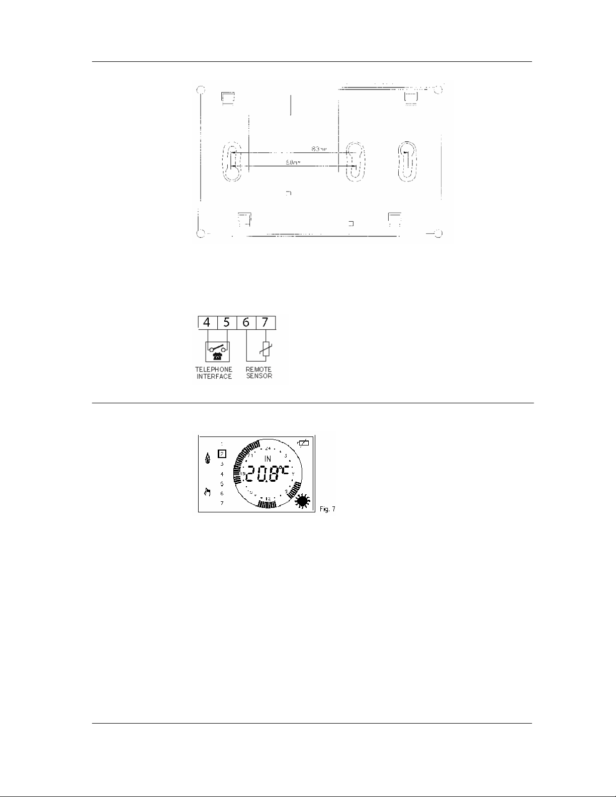
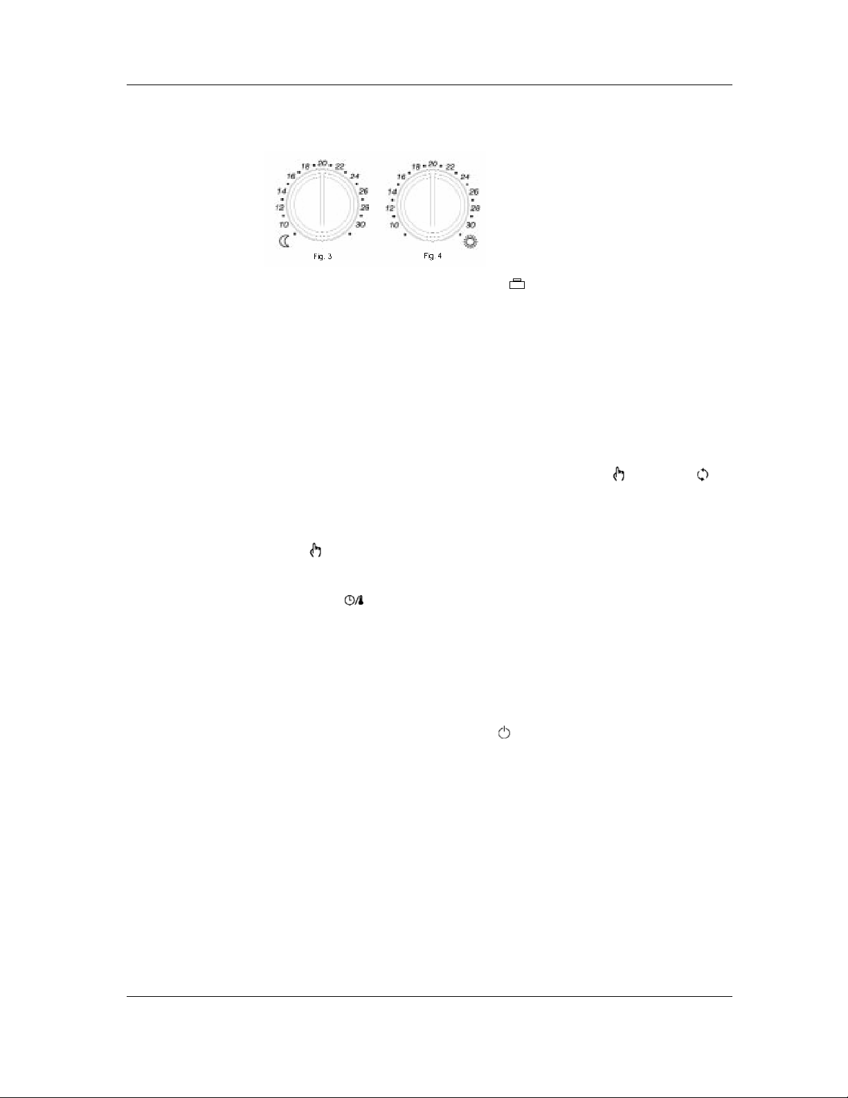
Wall Mounting The adapting plate (Fig. 3 below), can be fixed using the screws and relevant shells included in the
box or, alternatively, directly on the wall or on 3 modules junction boxes; on the plate will then be
hooked the chronostat body, by placing it from the plastic back side and sliding it down.
In any case, in order to grant the electrical safety, it is mandatory to screw the chronostat body to the
wall through the two screws supplied which must be mounted in the battery holder. The chronostat
must be located about 1.5 m. above the floor level, far from heat sources, doors and windows.

SyxthSense Ltd
Online Store: www.syxthsense.com Copyright ©2004 SyxthSense Ltd – 07/2004
Enquiries: T: 0870 20 80 100 F: 0870 20 80 200 PS TH6.20 – 4/8
Electrical Wiring
The chronostat does not need electric wirings, because it was developed to be a wireless
chronostat. However some terminals are available (10) Fig. 10 to connect in addition an external
remote sensor input and a telephone interface.
- 4 and 5: telephone interface (optional) for remote control of the chronostat.
- 6 and 7: remote sensor (optional).
Clock Adjustment
In order to set the clock of MAGICTIME RADIO (Fig. 7), follow these steps:
1. Open the plastic door covering batteries.
2. Press the button '' for at least 2 seconds.
3. Set the day with buttons '▲' or '▼.
4. Confirm with button 'OK'.
5. Adjust current hour with buttons '▲' or '▼.
6. Confirm with button 'OK'.
7. Adjust current minutes with buttons '▲' or '▼.
8. Confirm with button 'OK'.
After 1 minute of inactivity on buttons, the chronostat will automatically exit the clock
adjustment mode.

SyxthSense Ltd
Online Store: www.syxthsense.com Copyright ©2004 SyxthSense Ltd – 07/2004
Enquiries: T: 0870 20 80 100 F: 0870 20 80 200 PS TH6.20 – 5/8
Heating/Cooling
Selection Pressing for at least 3 seconds the button '▲' (back) the Heating mode is selected
and the symbol ' ’ appears.
Pressing for 3 seconds the button '▼’ (forward), the Cooling mode is selected and
the symbol ' ‘ is displayed.
When batteries are replaced, the heating or cooling mode must be reprogrammed.
Programming mode The selection of the programming mode is made through the buttons '▼’ (forward),
'▲' (back), 'OK' (confirmation) and 'P' (programming).
To enter the programming mode the button 'P' must be pressed for at least 2 seconds:
the display will show one of the following day combination:
Press '▼(forward) or '▲' (back) to change and 'OK' to confirm.
Pressing the 'P' button, will exit the programming mode.
After the confirmation of the day combination (with 'OK' button), a time cycles combination
will flash on the display.
Through the 4 buttons '▼(forward), '▲' (back), 'OK' (confirmation) and 'P' (programming),
combinations can be selected: (from 1 per day minimum, to 4 per day maximum):
a) 1 time cycle:
b) 2 time cycles:
c) 3 time cycles:
d) 4 time cycles:
06:00 ..... 23:00
06:00 ..... 08:00
17:00 ..... 23:00
06:00 ..... 08:00
11:00 ..... 13:00
17:00 ..... 23:00
06:00 ..... 08:00
11:00 ..... 13:00
17:00 ..... 19:00
21:00 ..... 23:00
After confirming with 'OK' button the selected time cycle, it is possible to modify through buttons '▼
(forward), '▲' (back) and 'OK' (confirmation), its start and end time with a minimum step of 15
minutes. After the programming of the first combination of days and time cycles, it is possible to
program the next combination (if present).

SyxthSense Ltd
Online Store: www.syxthsense.com Copyright ©2004 SyxthSense Ltd – 07/2004
Enquiries: T: 0870 20 80 100 F: 0870 20 80 200 PS TH6.20 – 6/8
Temperature Setting Through the two knobs (Fig. 3 and 4) ' ◖‘ (moon) and ' ☼‘(sun) it is possible to adjust the 'Economy'
and the 'Comfort' temperatures as set by the program.
Vacation Program If the 'Vacation' combination is selected, the symbol ' ’ (luggage) will flash: pressing the 'OK'
button (confirmation) it will be possible to set with buttons '▼' (forward) and '▲' (back) the number of
hours (h. 00..95). Once reached the max hours number the display will automatically switch to days
indication (d. 04..99). During this period the heating or cooling will be off (only the antifreeze
function will remain active). When the antifreeze program is activated, the current hour or day will be
included: in this case (but only in heating mode), the antifreeze temperature is displayed and can be
modified with the buttons '▼(forward) or ‘▲’ (back).
Manual Mode
Pressing the 'manual' button (1) the chronostat can be forced to operate in a different mode from the
one set by the current program.
Pressing it once an 'override' function is activated: the temperature is regulated according to the
opposite level (Comfort in place of Economy or vice versa) with respect to the one currently selected
by the program, until the next action of the program occurs. In this way the next action is 'anticipated'
by this 'override' function.
The chronostat, will return in normal mode on the next action, the symbols ' ‘(manual) and '
'’(override) will be on and the time cycles are visible. In this mode the room temperature is still
displayed.
Pressing twice the manual button, the chronostat will be forced in continuous 'Comfort' temperature
mode, while pressing once again it will be forced in continuous 'Economy' temperature mode;
symbols ' ‘(manual), ' ☼‘(sun) and ' ◖‘ moon) will be on and the room temperature will be
displayed. If the manual button is pressed once again, the chronostat returns in normal mode.
Time / Temperature
Display
By pressing the ' ‘button (3) you can display the current time; in case an external sensor is wired
to the relevant terminals by repeatedly pressing the same button you can even display the internal
(the label 'IN' appears on the display) or external temperature (the label 'OUT' appears).
In case no external sensor is wired to the terminals, the regulation is made with respect to the
internal one.
On the other hand when an external sensor is wired, you can choose the reference sensor (internal
or external) for the regulation by moving the relevant microswitch located on the thermostat back.
See section “Additional functions”
Turn-on / Turn-off
The chronostat can be turned off by pressing the ' ‘button (2) which (only for
heating mode) will force the regulation at an adjustable temperature level between -
5°C e 25°C through the '▼' (forward) and '▲' (back).

SyxthSense Ltd
Online Store: www.syxthsense.com Copyright ©2004 SyxthSense Ltd – 07/2004
Enquiries: T: 0870 20 80 100 F: 0870 20 80 200 PS TH6.20 – 7/8
Additional Functions
The presence of 4 microswitches located on the chronostat back (Fig. 10) gives access
to some additional functions.
The chronostat is factory set with the microswitches in the following configuration:
1. Test mode
This microswitch in the lower position enables the ‘Test’ mode. In this mode the chronostat issues
radio commands continuously for testing the communication with the receiver. The commands toggle
the relevant relay in the receiver every 3 seconds. Once the set-up and tests are finished, set the
microswitch in the upper position.
2. Optimization
The optimization function gives the chance to turn the heating on with a time advance with respect to
the programmed time so that the user will actually have the desired temperature (that is the set one)
at the programmed time. Actually the chronostat measures the time the environment needs to get to
the desired temperature and, consequently, anticipates the programmed turn on by the time needed
to get to this goal. The optimization can be activated by moving a microswitch located on the
thermostat back: the time advance is calculated with respect to the average temperature gradient in
the last 24 hours, with a maximum of 60 minutes time advance.
3. Time proportional operation
By moving this microswitch located on the rear of the chronostat the user can switch between the
standard operation (on-off with an asymmetrical 0.2°C differential) and a time proportional operation
with a band and intervention times that fit the most of civil environments.
4. Internal - External sensor selection
By moving this microswitch located on the rear of the chronostat the user can select as a reference
sensor for the regulation either the internal sensor or the external (remote) one.
Batteries replacement
When on the display shows the battery symbol ‘ ‘, batteries must be replaced.
In order to perform this operation proceed as:
1. Open the plastic door covering the batteries.
2. Remove old batteries with the help of a small tool.
3. Insert the new batteries which must be 1.5V AA alkaline.
4. If the chronostat seems not to operate well, perform a reset through button (7).
WARNING !
- To determine the correct position one must ensure that the radio signals transmitted are
correctly received by the receiving unit.
- To adjust properly room temperature, install the thermostat far from heat sources,
airstreams or particularly cold walls (thermal bridges). When the remote sensor is used in
conjunction with the thermostat, then this note is to be applied to the remote sensor itself.
- For remote version all wirings must be made using wires with 1,5 mm² minimum section and
no longer than 3 m. Do not use same duct for signal wires and mains.
- Installation and electrical wirings of this appliance must be made by qualified technicians
and in compliance with the current standards.

SyxthSense Ltd
Online Store: www.syxthsense.com Copyright ©2004 SyxthSense Ltd – 07/2004
Enquiries: T: 0870 20 80 100 F: 0870 20 80 200 PS TH6.20 – 8/8
Notes: In the view of a constant development of their products,
the manufacturer reserves the right for changing technical data
and features without prior notice. The consumer is guaranteed
against any lack of conformity for 24 months from the time of
delivery, according to the European Directive 1999/44/EC. The
full text of
g
uarantee is available on re
q
uest from the seller.
Other SyxthSense Thermostat manuals
Popular Thermostat manuals by other brands

LUCHT LHZ
LUCHT LHZ Technotherm VPN DSM 750 Installation and operating instructions

ABB
ABB HA-S-1-WL product manual

Sensi
Sensi 1F95U-42WF Series user manual

Salus
Salus ERT30 instruction manual

Honeywell
Honeywell Super Tradeline T874R installation instructions

Honeywell
Honeywell PROGRAMMABLE THERMOSTAT RTH6350 operating manual