T-Motor T-DRONES M690PRO User manual

M690PRO
Long Flight Time Flight platform
2
01 MAIN FEATURES
02 FEATURES
04 PRECAUTIONS
03 SPECIFICATIONS
Being a platform of ultra-light, long endurance and multiple applications, this aircraft can be employed for various missions
with corresponding equipment including aerial photography, mapping and surveying,meteorological monitoring, surveillance,
military supervision and geoexploration etc. Custom solutions are also available.
The endurance of M690PRO reaches up to 55mins (1kg payload). The abundant flight time enables more mission
accomplishment in one flight. It can be adapted to a variety of devices with flexible and diverse mounting methods.It is easy
for the M690PRO to shuttle in different environments with long communication distance, excellent protection capability and
a portable backpack.
Ultra-light materials and structural optimization to obtain longer flight time.
The low center of gravity design makes the aircraft more reliable.
Enhanced protection level;Ease of use.
The arms, landing gears and propellers can be folded and disassembled quickly.
Chute design for easy installation of battery.
No tools required. Only 3 minutes to get ready to fly.
For the safety and steady operation of drones during assembly and calibration, please make sure all parameters are at the
proper values before takeoff.
700mm
Wheelbase 1.69kg (incl. Propulsion system & FC)
Frame Weight
3.69kg
Weight(no payload) 2.23kg (Smart battery),
1.95kg (Li-ion battery)
Battery Weight
AUW 5m/s
Max. AscendingSpeed
6kg
Max.descending Speed Max.cruising Speed 15m/s3m/s
Hover Precision Hover Time 1kg payload≥55mins;
2kg payload≥40mins
Vertical ±0.2m;
Horizontal ±0.1m
(Without RTK)
Protection Level Wind Resistance Level 14m/sIP54
Working Environment Propulsion System T-MOTOR﹣1 5 ℃ ~ 5 0 ℃
Control System Unfolded Size 550*550*445mm (Excl. Props)
PIXHAWK
UNBOXING WARNING
Folded Size Packing 420*370*280mm (standard);
510*420*340mm (Backpack)
283*278*175mm
(incl. Landing gears; excl. props)
Package Weight 6.6kg

3 4
Please carry out proper debugging and checks on every part of the drone Any minor neglect may result in severe damages
or accidents.
INSPECTIONS BEFORE TAKEOFF
1.After landing, ensure that the remote control is locked, and then cut off the power supply of the UAV.
2.Check the battery power. Inspect UAV appearance and equipment loaded.
3.Tidy up the equipment after the demonstration.
AFTER LANDING
1.When debugging the UAV, it is necessary to ensure that the propeller is not installed on the motor (it is forbidden to debug
the aircraft when the propeller is installed on the motor, otherwise accidents may occur).
2.Close takeoff is strictly prohibited. Keep a distance of more than 5 meters from the UAV when taking off.
3.It is strictly prohibited to suddenly push the throttle to take off to avoid uncontrollable accident.
4.It is strictly forbidden for non-test personnel to move the remote control to avoid accidents caused by misoperation.
5.Under NO circumstances should anyone touch the UAV in landing.
6.It is strictly prohibited to pick up the UAV when the propellers are rotating after the aircraft lands.
PRECAUTIONS
1.Before power on the system, please check on the appearance and condition of the mechanical parts and propellers. If
there are stains and cracks on the propellers, please replace them with new ones. Make sure: the rotation direction of the
propellers are correct; propellers are tightened; no interference in rotation when turning them by hand.
2.Please make sure that: the motor installation is tight.If it is not loose, stop flying and fix the motor installation with
appropriate tools; there is no jamming with the motor when rotated by hand; the motor coil is clean; and there is no obvious
bend with the shaft.
3.Please make sure the frame is firm and the screws are not loose.
4.Please make sure the battery is installed correctly, and it is sufficiently charged.
5.Please make sure the center of gravity of the UAV is correct.
FRAME CHECK
1.To avoid damage, please make sure if series or parallel circuits are required when connecting batteries.
2.Unlock and pull the throttle slightly to check if the motors rotate normally after pairing.
3.Check on all the electronic devices and make sure they works normally.
4.Calibrate the magnetic compass as per the manual.
5.Test flight to see if the aircraft proceed as per the preset route or if the route requires any adjustment.
6.During the test flight, it is necessary to observe the status of the UAV lights and the number of GPS stars displayed by the
ground station in advance to make a timely prediction.
7.Make sure the remote control distance of the flight is six to seven meters on the left and right sides of the UAV. Avoid
standing directly behind the tail of the UAV.
8.After completion, power on and let GPS adapt to the weather, so that the UAV can adapt to the weather during operation
and fly perfectly.
9.Before take-off, the number of GPS stars must be 17 or more, and make sure the surrounding conditions are favourable
for take-off.
GROUN D STATION CHECK
1.The pilot must always pay attention to the UAV's attitude, flight time, aircraft position and other important information.
2.When flying at a distance, the security person is required to report the real-time status of the UAV through the intercom.
3.It is necessary to ensure that the UAV has enough power to return safely.
4.When flying beyond the visual range, it is necessary to closely monitor the UAV attitude, altitude, speed, battery voltage,
number of GPS satellites and other important information displayed in the ground station.
5.After takeoff, pay attention to the flight status of the UAV, grasp the flight data of the UAV in real time, and ensure that the
flight data indicators are in good condition.
6.If the UAV encounters a major failure and inevitably crashes, it must first ensure the safety of personnel.
IN FLIGHT

5
05 ASSEMBLY
1.Content ( Fi g u r e 1)
2.Take out the frame and spread. (Figure 2)
( Fi g u r e 1)
(Figure 2)
3Body: 1PC
1Propeller: 2 Pairs
4Landing gear: 2 Sets
2Motor accessories: 1 bag (GPS stick*1, 3M tape*5, motor accessories*4 )
5Gimbal parts: 1 bag (gimbal hook*4, M2.5*8 screw*4, M3*8 screw*4)
6
3.Spread the arms to 180 degrees and turn the folding rings as per the instruction and secure the arms.(Make sure the
arms are lined up with the frame, otherwise, they might get stuck and cause damage to the thread. )(Figure 3)
4.Assemble the landings gears to the frame as per Figure 4.
(Figure 3)
(Figure 4)
1
2
3
4
5

7
5.Attach the landings gears to the frame as per Figure 5. Assembly completes as shown Figure 6. (Please be aware of the
limiting structure on the landing gear, and make sure they are in place before secure the rings. )
(Figure 5)
8
06 FC INSTALLATION (Pixhawk)
1.Remove the upper cover of the frame(Figure 7)
1.Take off the flight control mounting plate.(Figure 8)
(Figure 7)
(Figure 8)
(Figure 6)

9
4.Set the mounting plate onto the frame.(Figure 10)
(Figure 9)
(Fig ure 10)
3.Fix the flight control on the plate.(Figure 9)
10
5.Put the GPS wire into the GPS holder from the side, and stick it to the holder with 3M tape. Then turn the GPS fixing ring
clockwise to the frame. (Please be aware of the limiting structure on the GPS holder, and make sure they are in place
before secure the rings. )( F i g u re 11)
6.After all connection are made and flight control is adjusted, fix the top cover.(Figur e 12)
( Fi g u r e 11)
(Fig ur e 12)

07 DISASSEMBLY OF GIMBAL SHELL AND ADAPTER
7.Install the propeller according to Figure 13. Propeller installation completed as shown Figure 14.
(Make sure CW and CCW are in place.)
1.Remove gimbal shell.(Figu re 15)
2.Assemble the gimbal adapter.(Figure 16)
(F igu re 13)
(Figure 15)
(Fig ure 16)
(F igu re 14)
11 12

08 COMPONENTS
1.Wheelbase.(Figure 19)
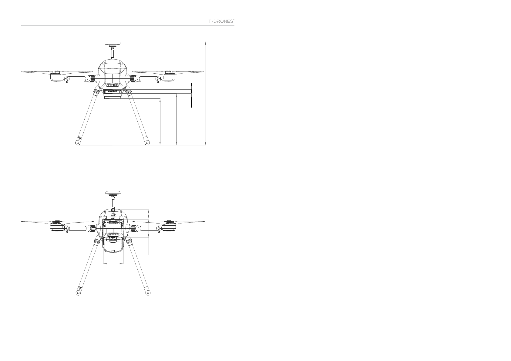
1.Other sizes (Figure 20&21)
a.FC installation height:40mm b.Battery case: 87.6mm*77.5mm
c.Inner size for gimbal: 17mm d.Mounting height for gimbal: 230mm
e.Gimbal shell height: 208mm f.Height of M690PRO: 462.5mm
13
09 DIMENSIONS
14
1
2
7
8
10
10
13
15
14
16
17
4
6
5
9
3
(Figure 17 Front view)
(Figure 19 Front view)
(Figure 18 Back view)
1GPS
13 Top cover 14 Switch button 15 Frame 16 Back cover 17 Gimbal shell
7Carbon tube
11 Shock absorber 12 Power button
8Arm fixing ring 9Landing gear fixing ring 10 Landing gear tube
2GPS holder 3Propeller 4Motor 5Motor mount 6LED cover
700mm
15
(Figure 20)
208
462.5
230
17
87.6
77.5 40
Table of contents


