TAG Heuer HL 610 User manual

1
_______________________________________
P R O F E S S I O N A L T I M I N G
IMPULSES RADIO TRANSMISSION SYSTEM
HL 610
OPERATING INSTRUCTIONS
1. DESCRIPTION OF THE FUNCTIONS ....................................................................... page 2
2. DESCRIPTION OF THE SYSTEM ............................................................................... page 4
3. TEST AND FUNCTIONING PRINCIPLE OF THE SYSTEM........................................ page 5
4. INSTALLATION OF THE TRANSMITTERS AND THE RECEIVER ........................... page 6
5. ACCUS AND BATTERY CONTROL ........................................................................... page 7
6. TECHNICAL SPECIFICATIONS ................................................................................. page 8
GPI / 07.12.03

2
1. DESCRIPTION OF THE FOUNCTIONS
TRANSMITTER
98
7
5
4
6
1
RECEIVER
9 10
5
4
3
2 2

3
1. DESCRIPTION OF THE FUNCTIONS (Following)
1. INPUT Input for timing impulses (Start gate, photocell – working / closing contact).
Respect the polarities.
2. OUTPUTS Outputs of the timing impulses isolated by optocoupler (1 to 4 – working /
closing contact). Respect the polarities.
3. POWER To switch on of the receiver (press during 3 seconds on POWER). The red
LED is on. To switch off the receiver, activate SET and press POWER.
4. SET To program the TEAM (A, B, C, D) or CHANNEL (1, 2, 3, 4) and to switch off
the receiver. Maintain SET pressed during the changes.
5. TEAM To check the programmed TEAM. The green LED corresponding to the code A,
B, C or D is on. To change the code, activate SET and press TEAM.
6. CHANNEL To check the programmed CHANNEL. The green LED corresponding to the
CHANNEL 1, 2, 3 or 4 is on. To change the CHANNEL, activate SET and press
CHANNEL.
7. TEST To test the impulses transmission.
8. BATT To check the state of the battery.
9. LEDS Control LED of the programmed TEAM or CHANNEL. Allows to visualize the
transmitted impulses by the transmitter or received by the receiver.
.
10. LEDS LED to monitor the signal quality of the received impulses / or possible
interferences created by other radio signals.

4
2. DESCRIPTION OF THE SYSTEM
Low power impulses transmission system (10 Mw) which doesn’t need any license (free of
use) in Europe (ISM Band – 433.56 MHz).
Each receiver can receive impulses (simultaneously or not) from 4 transmitters identified by
the function "CHANNEL" (1 to 4).
Up to 4 teams can work (train) in the same area without disturbing each others thanks to the
function "TEAM" which offers the possibility to code each system (A, B, C, D).
It is also possible to use up to16 transmitters with 4 receivers.
The transmitter is equipped with a lithium battery insuring an autonomy of approximately 3
years. There is no switch ON / OFF.
The receiver is equipped with an internal accumulator insuring an autonomy of at least 24
hours at 20 °C. Approximately 10 hours of charging may be necessary to obtain the maximum
capacity.
When the receiver is switched on, it is possible that one or more green LED’s are on before
that the transmitter(s) start to transmit. This system of detection allows to visualize the quality
of the received signal, but also the possible interferences coming from other radio
transmission systems. If it is not possible to stop these interferences by moving the receiver,
the transmission of impulses cannot be guaranteed.
THE INSTALLATION INCLUDES:
1 Plastic case which can contains up to 4 transmitters
1 to 4 transmitters
1 Receiver
2 to 5 antennas and 1 adapter right angle BNC
1 Charger 100-240 VAC / 9VDC
1 User manual
Remark: If the SET that you received contains an antenna longer than the others, it is intended for
the receiver.

5
3. TEST AND FUNCTIONING PRINCIPLE OF THE SYSTEM
Connect the antennas on the receiver and transmitters. The antennas must always be
positioned vertically. Use the adapter right angle BNC if the receiver is placed horizontally.
Switch ON the receiver by pushing approximately 3 seconds on POWER. The red LED is on
(see chapter 6 ).
Check the programmed "TEAM" (A, B, C or D) on the receiver and the transmitters. It must
be identical for each system. To change it, activate SET and press TEAM.
Check the programmed channel N° (CHANNEL) on each transmitter (1, 2, 3 or 4). This N°
corresponds to the OUTPUT N° of the receiver. This / or these OUTPUTS are connected to
the timing device. To modify the OUTPUT N°, activate SET and press CHANNEL.
Press TEST on the transmitter (transmission test)
- The green LED of the transmitter (1 to 4) corresponding to the selected channel N° is on
and a “beep” signal confirms the sending of the impulse.
- The green LED of the receiver corresponding to the channel N° of the transmitter (1 to 4)
is on and a “beep” signal confirms the reception of the impulse which is provided on the
corresponding output (1 to 4) to the timing device.
-The 4 green LED’s on the receiver unit allows you to monitor the quality of the signals being
received.
1 led is on - > Very weak Signal
2 led’s are on - > Weak Signal
3 led’s are on - > Signal satisfactory
4 led’s are on - > Good Signal
(see chapter 2. “Description of the system HL 610”)
At the end of the test or use of the system, do not forget to switch off the receiver !
Activate SET and press POWER

6
4. INSTALLATION OF THE TRANSMITTERS AND THE RECEIVER
The HL 610 must be used in an open environment. Difficult topography (Undulating country),
obstacles or trees can significantly decrease the performances of the installation. It is in all the
cases recommended to place the transmitters in the highest possible location for a maximum
reliability.
Installation methods (Transmitters)
Optimal Satisfactory Very good
To fix the transmitters on wooden-post, skis or photocells, you can use Velcro, Straps, Serflex or
quick fixation. Tag Heuer will be able to provide you a specific product during January 2004.
The receiver can be fixed vertically or positioned horizontally using the right angle BNC adapter.
WARNING !
The antennas should not be hidden. They are mounted vertically with a direct view
between transmitter and receiver.

7
5. BATTERY AND ACCUMULATOR CONTROL
TRANSMITTER
Press BATT to check the battery power condition.
Good battery: 2 « BEEPS » will be heard and 4 green LED’s are on.
Rather good battery : 2 « BEEPS » will be heard and 3 green LED’s are on.
Acceptable battery : 2 « BEEPS » will be heard and only 2 green LED’s are on.
It is possible by huge cold (-10°C/ -15°C) to find this situation. The power of the Battery decreases
and can make believe that this one is out of use.
Bad battery : 3 « BEEPS » will be heard and only 1 green LED is on. You must replace
the battery, a normal use is no more guaranteed.
Discharged battery: 3 « BEEPS » will be heard and no green LED is on. The system is out of
use.
ATTENTION !
If the battery of the transmitter is out of order or defective, we recommend to contact
your local TAG Heuer Timing Agent. At the same time, you will have the opportunity
to control the accumulators of the receiver.
RECEIVER
When the receiver is switched on, the control of the accumulators conditions is ensured by the red
LED POWER.
Accu charged : The red LED is on.
Accu slightly
discharged : The red LED flashes each second.
Accu discharged : The red LED flashes very fast (more than 1 per second) The good
functioning of the system is no more guaranteed.
To recharge the receiver, use the original charger AC/DC provided by TAG Heuer. The use of
another charger can seriously damage or destroy the device.
-Switch off the receiver to recharge the accumulators (POWER OFF).
- Connect the charger to a normal household ac current receptacle.
- Connect the jack of the Charger to the receiver.
- The red LED POWER flashes during the charging.
- 10 hours can be required to fully recharge the receiver if this one was totally discharged.
Remark : It is possible to use the charger during the timekeeping with the receiver switched on.
However, no particular message will be given by the LED POWER.

8
6. TECHNICAL SPECIFICATIONS
Type of emission : ISM Band – 433.5 6MHz
Code : 4 differentiated Channels (A, B, C, D)
Radiated Power Output : 10 mW
Range : Superior to 2 km under optimal conditions, direct view
Antenna : Multiflex 1/4
Timing Impulse Inputs: Open Working contact. Respect the polarities (Black = Ground)
Timing Outputs: 4 opto-isolated independent output
Precision : Fixed delay of 100ms +/- better than 1/10,000th second.
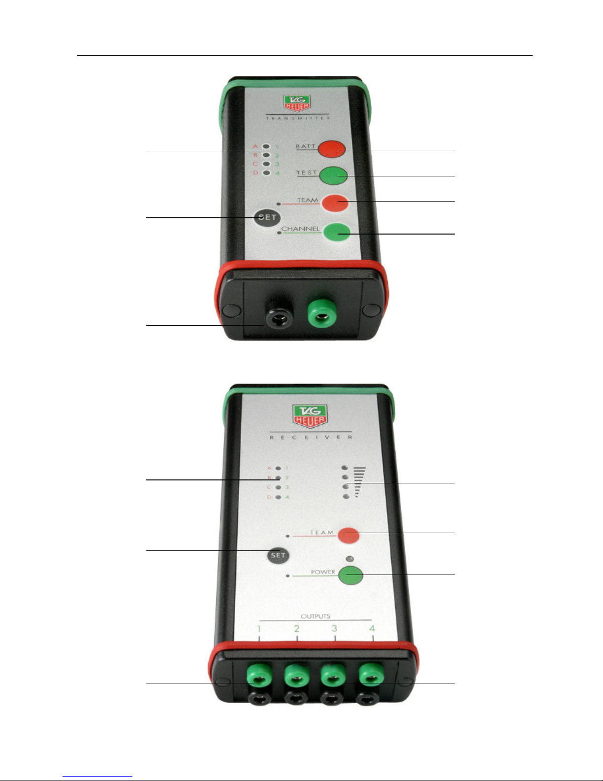
Signal Transmission Evidence: By audible tone (buzzer) and LED (1, 2, 3, 4)
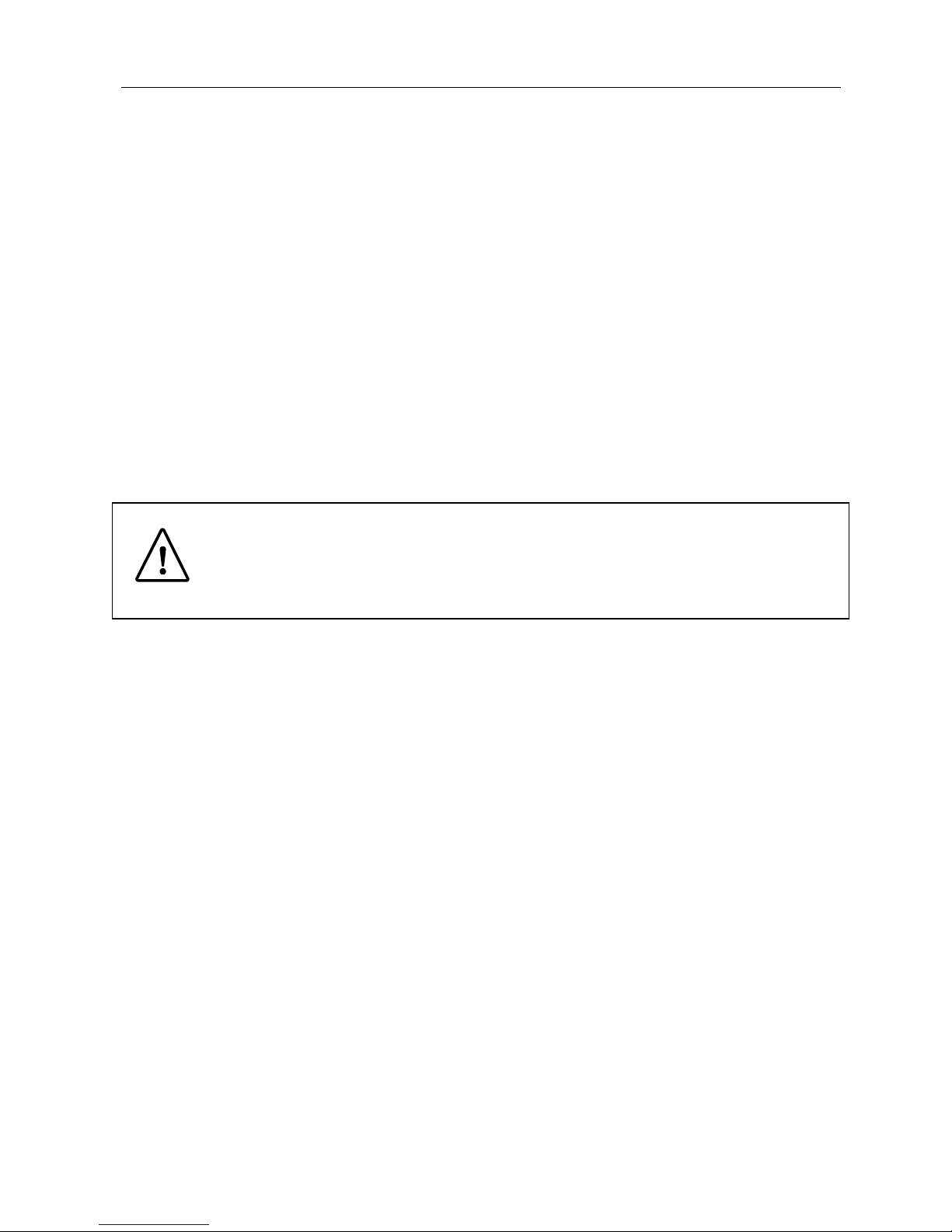
Signal Reception Evidence: By audible tone (buzzer) and LED (1, 2, 3, 4)
Signal Reception Monitoring : By 4 LED’s. Control of the quality of the reception and of
eventual disturbances.
Battery Condition Monitoring: By red LED (POWER)
On -> well charged
Flashing -> to be recharged
Power Supply : By internal battery (lithium) for the transmitter and by internal
rechargeable accumulator for the receiver
Charger : AC/DC Adapter
100 – 240 VAC / 9VDC – 550 mA
Polarity : positive at the center of the plug
Autonomy : Approximately 3 years for the transmitter
Approximately 24 Hours for the receiver at 20°C
Operating Temperature Range: -20°C à + 60 °C
Mounting: By Velcro or Serflex strap
Dimensions & weight Transmitter : 100 x 57 x 32 mm / weight of 175 gr.
Receiver : 100 x 82 x 32 mm / weight of 380 gr.
Guaranty : One year starting from the purchase date
The guaranty is null and void under the following conditions:
- Accumulators or battery out of use
- Bad maintenance and obvious damages
- Input or Outputs damaged by bad connection
-If the device was open without factory authorization
Table of contents
Other TAG Heuer Microphone System manuals