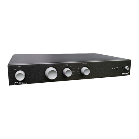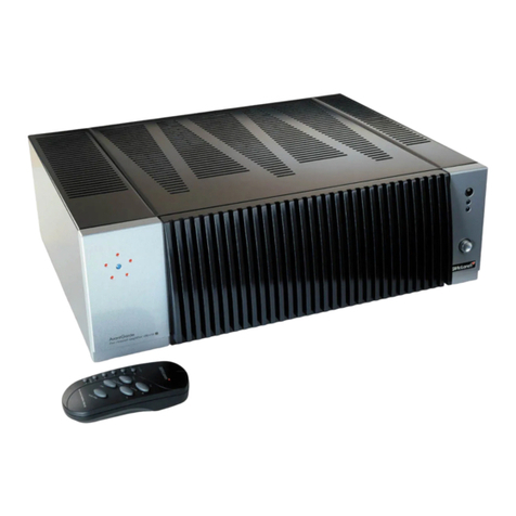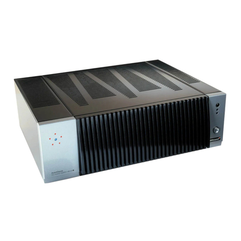
F3 series 100X5R service manual
index
1.0 safety and servicing notes
1.1 Safety precautions ........................................ 1
1.2 Electrostatic discharge precautions ............................ 1
1.3 Soldering .............................................. 2
2.0 front and rear panel layouts
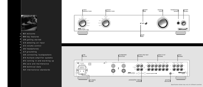
2.1 Front panel controls ...................................... 4
2.2 Rear panel connections .................................... 4
3.0 disassembly instructions
3.1 Removing case and fascia .................................. 5
3.2 Removing components .................................... 5
4.0 technical outline
4.1 Technical description ...................................... 7
4.2 50 way IDC harness ...................................... 8
4.3 Desciption of pins J1 ...................................... 9
4.4 100X5R block diagram ................................... 10
5.0 functional tests
5.1 Fault finding flow chart ................................... 11
5.2 Test equipment required .................................. 12
5.3 Functional test procedure ................................. 12
5.4 Biasing modules ........................................ 13
5.5 Adding modules ........................................ 13
6.0 performance tests
6.1 Test equipment required .................................. 14
6.2 Performance test procedure ................................ 14
7.0 upgrading software
7.1 Equipment required ...................................... 16
7.2 Upgrading software procedure .............................. 16
8.0 diagnostics
8.1 Upgrading software diagnostic messages ...................... 17
8.2 Resetting parameters ..................................... 17
9.0 circuit schematics
9.1 100X5R LED PCB - 1 sheet ................................ 18
9.2 100X5R IR PCB - 1 sheet .................................. 18
9.3 100X5R uC PCB - 3 sheets ................................ 19
9.4 100X5R AMP PCB - 2 sheets ............................... 22
9.5 100X5R TAG BUS PCB - 1 sheet ............................ 24
10.0 printed circuit board layout
10.1 100X5R LED PCB ....................................... 25
10.2 100X5R uC PCB ........................................ 26
10.3 100X5R TAG BUS PCB ................................... 26


