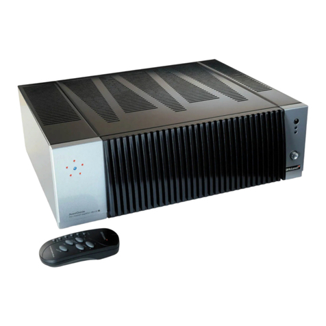
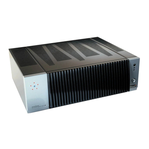
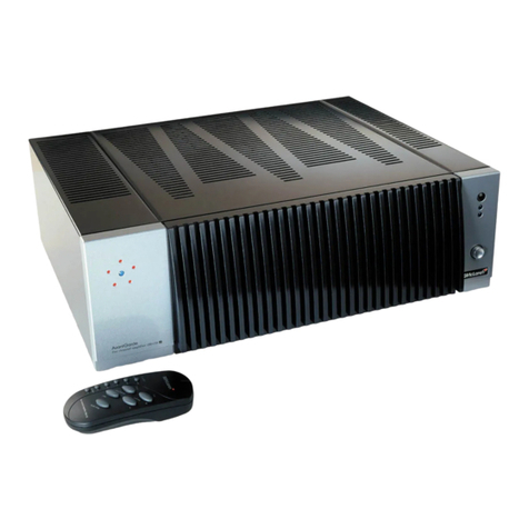
TAG MCLAREN AUDIO 250MR User manual

contents |01
02 controls
04 welcome
06 introduction
07 construction
08 amplifier module
15 set up
20 operation
21 remote control
24 TAGtronic Communications Bus
25 running in and warming up
26 care and maintenance
28 appendix
30 technical data
9339X
12/01
owner’s manual
250MR
GRR00794.03-UK 250MR 5/4/02 11:48 am Page 01

controls |0302 |controls
–
RISK OF ELECTRIC SHOCK
DO NOT OPEN
–
21
3
power/
standby LED remote control
window
remote control
active LED
220-240V
~50-60Hz
Fuse; T5A L250V
class 2 wiring
minimum rated
load impedance
8 Ωper channel
serial
number
made in United Kingdom by
monobloc 250MR s
OUTIN
BUS
LINE INPUT
–
+
LOUDSPEAKER
OUTPUT
CAUTION
RISK OF ELECTRIC SHOCK
DO NOT OPEN
DO NOT OPEN
Double insulated: When servicing, use only
identical replacement parts.
BALANCED
INPUT
ground
+
–
2 1
3
line level
input socket
TAGtronic
communications bus
loudspeaker
terminals
ac supply
socket and
fuse carrier
balanced
input socket
Specification shown may vary for different countries
GRR00794.03-UK 250MR 5/4/02 11:48 am Page 02

welcome |0504 |welcome
Pushing technological
boundaries; TAG McLaren’s
F1 electronics
Dr. Udo Zucker
Chief Executive Officer
TAG McLaren Audio
TAG McLaren Audio exists with one
aim in mind: to produce the very best audio
and audio-visual equipment.
Like many people, I often have my best
ideas when relaxing to a piece of music
or watching a movie. For years, knowing
the technical capabilities of TAG McLaren,
I have nurtured the ambition to push music
and movie reproduction to the absolute limit
without compromising ease of use; that’s
why we formed TAG McLaren Audio.
At the core of our development team are
highly experienced engineers whose
heritage of award-winning hi-fi and world-
beating electronic control systems is envied
by many and equalled by few.
There are many immediate spin-offs into
audio from our expertise in automotive
electronics, mechanical engineering and
the material science of Formula One motor
racing: multi-layer printed circuits, fast
digital signal processing, electronic noise
suppression, radio frequency technology
and software expertise to name but a few,
all prerequisites of an outstanding audio
product.
TAG McLaren’s aim is sonic perfection
combined with aesthetic delight and solid
build quality – a rare combination in hi-fi
but one which TAG McLaren Audio is
already delivering.
Dr Udo Zucker
welcome to
GRR00794.03-UK 250MR 5/4/02 11:48 am Page 04

construction |0706 |introduction
The 250MR houses a self-contained, hi-performance 250 W amplifier module, described in
detail on the following pages, and a control board, spaced apart for minimal interaction.
The 250MR achieves typically 255 W per channel into 8 ohms and 400 W into 4 ohms. Its
IHF tone burst performance is also impressive: typically 300 W into 8 ohms, 550 W into
4 ohms and 1000 (!) W into 2 ohms.
The monobloc 250MR is a refinement of the highly regarded three channel amplifier 250x3R,
using a single 250 W amplifier module and its associated control electronics in an attractive
case. This has many benefits:
The 250MR’s control electronics is powered
by an additional, tiny transformer and a
local power supply, allowing the 250MR to
be put into standby without incurring
a high energy bill.
The remote control
circuitry acts on
commands received
from either the user
via the IR remote
control or the AV32R
via the TAGtronic
Communication Bus.
The protection control
circuitry monitors the
performance of the amplifier in
order to power it down should a
fault occur.
A monobloc, also known as single
channel amplifier, is the ultimate
power amplifier configuration,
eliminating channel crosstalk and, if
placed close to a loudspeaker, the
influence of the loudspeaker cable!
Thank you for purchasing theTAG McLaren 250MR
• The 250MR can be placed
close to the loudspeaker,
resulting in extremely short
loudspeaker cables, which
in turn minimises their
influence. The result is
improved loudspeaker
control.
• Each 250MR
connects individually
to the mains supply,
reducing the
influence of the
mains cable and
hence potential
channel crosstalk.
• Adjacent amplifier modules,
located in the same enclosure
will interact with each other
through magnetic coupling,
which can be minimised but
never completely eliminated. This
is extremely small in the 250x3R,
but non existent in the 250MR!
control electronics
amplifier
module
main
transformer TAGtronic
Bus
control
electronics
tiny standby
transformer
GRR00794.03-UK 250MR 5/4/02 11:48 am Page 06

amplifier module|0908 |amplifier module
The 250MR power amplifier includes a self-
contained power module, as shown above.
The module is a complete amplifier, with its
own power transformer, bridge rectifier,
energy storage capacitors and amplification
stage, requiring only mains supply and
control signals to function.
Control signals are used to switch the
amplifier module on/off and to protect it in
case an error condition, such as a short
circuit in the loudspeaker, is detected.
the traditional TO3, enhancing the amp-
lifier’s reliability for many years to come.
exceptionally accurate quiescent stability
It is universally accepted that accurate
setting and stability of quiescent conditions
is crucial to optimal Class-B amplifier
operation. The bias range over which the
best linearity is obtained is narrow, and
on either side of it crossover distortion
increases markedly. The 250MR has one
of the most accurate quiescent controls
ever implemented, stabilising against
output level, load impedance and mains
voltage changes.
sophisticated muting
The 250MR has a sophisticated muting
system, which stops you hearing loud,
annoying switching noises and protects
both the amplifier and the loudspeakers.
Particular care has been taken to make
sure that the muting circuitry, when
switched off, doesn’t affect the sound
quality. For this purpose carefully selected
relays with minimal crosstalk between coil
and contacts have been used.
an optimised mix of global and local
negative feed back
The 250MR gives excellent linearity and
low distortion without relying on high global
negative feedback, which can present
difficulties when handling rapidly changing
signals. The amplifier implements at each
amplifying stage a controlled amount of
local feedback, which not only linearises
but also defines the gain and other vital
parameters closely.
cascode compensation
The 250MR uses an advanced stabilisation
concept called Cascode Compensation.
This might be the first time that this
sophisticated and elegant system has been
used in an audio amplifier. Its advantages
are excellent stability, inherently good
supply-rail rejection and a reduction in DC
drift. This gives outstanding stability with
performance drifts being virtually eliminated.
output transistors
The output devices are bipolar junction
transistors chosen for maximum linearity. The
advanced MT-200 package is used which
gives a greater area for heat transfer than
The module has a high-efficiency aluminium
heatsink for excellent heat dissipation,
allowing it to drive even the most critical
loudspeakers safely and dependably. This
results in uncompromised sound quality
with perfect channel separation.
Each 250MR delivers typically 255 Watts
into 8 ohms, 400 Watts into 4 ohms and
will drive 1000 Watts into 2 ohms for short
durations.
As a result of the 250MR‘s monobloc
construction, this performance is wholly
independent of the number of system
channels being driven and thus even
during the loudest passages of your
favourite movie the soundstage remains
stable, controlled and detailed.
There are many design features which have
been derived from our excellent 100x5R
and our F1-600MR amplifiers to make this
amplifier very special. We have listed a
few on the following pages.
deep under the skin
GRR00794.03-UK 250MR 5/4/02 11:48 am Page 08

amplifier module |1110 |amplifier module
low distortion
A theoretically ideal amplifier reproduces
sound perfectly over an infinite range of
frequencies - starting from well below the
audible range and extending far above the
capabilities of human hearing. Although
sound outside the human hearing range of
approximately 20 Hz to 20 kHz cannot be
heard, it can significantly distort the quality
of music reproduction through an effect
which audio engineers call ‘intermodulation
distortion’. This type of distortion moves
imperfections that originate outside the
hearing range back into the audible
frequencies. To minimise this effect, TAG
McLaren amplifiers have a frequency
response which extends both above and
below the range of normal human hearing.
straight line technology
An amplifier must respond to very low
frequencies but block any Direct Current
(DC) to prevent intermodulation distortion.
This is traditionally achieved using
capacitors, which also block some of the
low-frequency signals. In the 250MR, a
feedback circuit eliminates DC offset voltage
and allows the signal path to be direct
balanced XLR and standard RCA input
The 250MR provides both a balanced XLR
input and a standard RCA input. There is no
need to switch between the two inputs, the
250MR will automatically sense the input
used.
single ended RCA input
A single ended connection sends, as the
name implies, the signal via a two conductor
cable, one for the signal and one for the
ground (which is usually connected to the
screen on one or both ends).
The single ended connection is the most
commonly used connection type between
preamplifiers/av processors and their power
amplifiers. It works extremely well, even over
long distances, if the output stages of the av
processor/preamplifier are of a ‘low
impedance’ configuration, such as those in
the TAG McLaren AV32R or DPA32R.
However, if several products are connected
together it is possible for a current to flow
between the ground connections of those
units, caused by electro-magnetic
input interference or ground potential
differences. This current is indistinguishable
from the signal and hence can become, if
severe enough, audible as a hum or buzz.
The problem is usually referred to as
ground loops.
balanced line technology XLR input
A major advantage of balanced inter-
connects is the complete suppression of
ground-loop problems.
Balanced line inputs use 3 conductors, one
for the ground and two for the voltage
difference between the signal and the
ground at the preamplifier/av processor.
As a result the balanced input at the
amplifier does not respond to the voltage
between input and ground, which could be
altered by a ground loop, but to the
difference between the two conductors
carrying the signal.
For this system to work well, it is important
that the balanced input performs an
accurate subtraction of the signals at its
input terminals. The measure of how well it
does this is called the ‘common-mode
coupled without any capacitors, an
arrangement called ‘straight line’ technology.
The result is a very precise reproduction of
the lowest bass.
supersonic high frequency response
In order to reproduce high frequencies, the
250MR is constructed using highly rated,
high-precision components. The circuit has
been painstakingly designed to minimise
audio signals picking up interference and
intermodulating. Exceptional transparency
and purity of sound are the result.
GRR00794.03-UK 250MR 5/4/02 11:48 am Page 10

amplifier module |1312 |amplifier module
rejection ratio’. In the 250MR this is more
than 40 dB, or one hundred times, and best
of all, this is permanently fixed as it is set by
precision resistors rather than by attempting
to balance variable semiconductor properties.
combining a single ended av processor
with the 250MR
It is important to realise that a balanced
output on the sending unit, the preamplifier or
av processor is not required to gain the
benefits of a balanced input. A single ended
RCA output is just as good, so long as the
unbalanced-to-balanced cable is wired
correctly. TAG McLaren provides a special
version of its F3-10-ANA, manufactured with
an RCA connector at its input and a XLR
connector at its output. For more details see
www.tagmclaren.com or your authorised TAG
McLaren retailer.
The Appendix shows how an RCA-XLR analog
cable should be wired to provide ground loop
hum suppression, as described above.
Many small details lead to this exceptional amplifier, some key elements are covered below:
output
OFHC loudspeaker connections
For excellent sound quality the 250MR uses
TAG McLaren’s high grade oxygen free
high purity copper (OFHC) loudspeaker
terminals combined with a new knob made
from non-conductive Pocan.
Very few companies
provide OFHC
loudspeaker
terminals due to
the difficulties of
machining solid
copper, an
unacceptable excuse
for TAG McLaren.
The knobs for the 250MR have been
manufactured from non conductive Pocan
without a metal insert as it was found that
this gave the best sonic result, identical to
that obtained using an OFHC knob(1) (as
used on the TAG McLaren 100x5R).
1. safety regulations do not allow the use of a OFHC knob due to the very high voltage the 250MR can achieve at its loudspeaker terminals
when only the best is good enough!
premium-grade audio components
All components have
been carefully
selected and
auditioned before
a decision about
their use in the
250MR was
made. For
maximum
performance ultra-
stable Vishay metal film
resistors and low dielectric loss Wima poly-
propylene capacitors have been selected,
providing the increased transparency and
excellent noise suppression which
audiophiles attribute to these components.
mixed technology construction
With surface mount components for fast
digital signal transfer and leaded through
hole components for perfect audio signals,
the 250MR incorporates
mixed technology
construction to
optimise performance.
The result is uncom-
promised sound in a
small size.
aluminium for performance
The complete case, cooling fins and module
construction is made from Aluminium instead
of commonly used, cheaper mild steel.
Aluminium has been used as extensive
listening and laboratory tests
demonstrated that the
stray fields, albeit
minimal for a toroidal
transformer, were
interacting with
ferromagnetic
material in their
vicinity.
GRR00794.03-UK 250MR 5/4/02 11:49 am Page 12

set-up |1514 |amplifier module
brass instead of steel
The bolt holding the
heavy transformer
has been made
from brass
instead of steel
as this was also
found to make a
difference to the low
frequency impact of the
amplifier. Higher cost
well invested.
beauty to last
The finned fascia is
machined to high
accuracy from a
solid aluminium
extrusion and is
then painted.
vibration damping
The cover panel is
bonded with
viscoelastic
laminate to
provide a low Q
assembly which
provides rapid
absorption of
externally induced
vibrations.
preparation
We know you are keen to get your 250MR working. This section will have you
listening as quickly as possible. The controls diagrams located on pages 2 and
3 of this manual will help you find your way around your 250MR(1).
safety first
To prevent the risk of electric shock follow
these instructions carefully. If in doubt consult
a qualified electrician.
before you start
Make sure that all the components of your
system are disconnected from the AC supply
whenever you change any connection.
If the unit is not to be used for some time,
withdraw the mains plug from the wall socket
outlet.
positioning
The 250MR is capable of consuming over
650 Watts of electrical power during
demanding presentations. This results in
significant heat being dissipated.
1. Throughout this instruction manual, bold print indicates the lettering that you will find on the panels of your 250MR and the Remote Control
• Please ensure that there is adequate
ventilation above and below the unit.
• The ventilation of the 250MR should
not be impeded by covering the
ventilation slots with items such as
newspapers, table cloths, curtains etc.
• Place the 250MR on an open flat
surface.
• Do not use in a cabinet or on a soft
surface such as a carpet.
• Do not place any other piece of
equipment on top of the 250MR.
• Do not place naked flame sources such
as lighted candles on the 250MR.
• Do not expose the 250MR to dripping
or splashing liquids.
• Do not place objects filled with liquids,
such as vases, on or near the 250MR.
GRR00794.03-UK 250MR 5/4/02 11:49 am Page 14

set-up |1716 |set-up
Before making any connections ensure that the mains plug is
removed from the rear panel power socket You will require an av processor, such as the AV32R or a preamplifier, such as the DPA32R
to provide the signal to drive the 250MR.
power connection
loudspeaker connection
The contacts of the loudspeaker terminals of this amplifier (marked with the
lightning symbol) have hazardous live voltages present. If in any doubt, consult
a qualified electrician before making connection to these terminals.
On the rear panel of the 250MR you will find a pair of loudspeaker
terminals. The terminals are designed to accept high quality
8 mm spade connectors. Use only high quality ready made cables
with insulated spade connectors such as the TAG McLaren Audio
F3-10-SPK.
Ensure that the amplifier mains plug has been removed from the
wall socket before connecting the red (+) terminal of the
loudspeaker to the red terminal on the rear panel of the 250MR. In
turn connect the black (–) terminal of the loudspeaker to the black
terminal on the 250MR.
When making the connection, ensure that the spade terminal is
correctly located and the loudspeaker terminal is fully tightened.
av processor or preamplifier connection
Make sure the av processor/preamplifier and all connected source units, such
as a CD player are switched off and their mains plugs have been removed
from the wall sockets.
The 250MR provides a single ended line input (RCA) and a balanced XLR connection.
Do not connect XLR and RCA at the same time to an external source as this
will cause severe distortion and can damage your equipment.
Do not leave an un-terminated cable attached to an unused input.
GRR00794.03-UK 250MR 5/4/02 11:49 am Page 16

set-up |1918 |set-up
using the line input (RCA) how to connect a single ended RCA output to the balanced XLR input
If you are connecting to equipment with single ended RCA outputs and you would like to use
the balanced XLR input for best ground loop suppression, then use a suitably manufactured
RCA/XLR adaptor cable, such as our RCA-XLR F3 10-ANA interconnect. This connection is
recommended by TAG McLaren. More details to the cable are found in the Appendix.
The signal connection of the RCA input and the XLR are connected internally.
Do not connect both connections at the same time as this might damage your
equipment!
The signal connection of the RCA input and the XLR are connected internally.
Do not connect both connections at the same time as this might damage your
equipment!
When the RCA input is used the XLR shorting link, fitted when you
receive the 250MR from the factory, must be inserted between pin 1
and pin 3 of the XLR input connector. This is necessary to obtain the
correct gain and to reduce the noise pickup.
If you connect an RCA output of your av processor or preamplifier
with the RCA line input of the 250MR then you should use a hi-
quality, well screened RCA-RCA audio cable, such as our RCA/RCA
F3-10-ANA interconnect.
using the balanced input (XLR)
In order to use the XLR connection you need to remove the XLR shorting plug, if connected.
Please store the shorting plug safely for later use.
If your are connecting to equipment with balanced outputs then use a high quality XLR-XLR
cable, such as our XLR/XLR F3-10-ANA interconnect.
GRR00794.03-UK 250MR 5/4/02 11:49 am Page 18

remote control |2120 |operation
When you have completed the set-up and have connected all cables between all
components, ensure that the volume control on the av processor/preamplifier is set to
minimum before reconnecting the mains plugs and switching on all equipment.
Make sure you use the mains cable supplied for your 250MR.
apply mains power
When power is applied the blue power LED will come on.
The red mute indicator LED illuminates while the amplifier is
powering up and internal conditions stabilising.
When the amplifier has stabilised, the mute LED goes out(1). Then
the amplifier is ready to play source material through the system.
Raise the volume level at your av processor or preamplifier slowly
at first, until sound is replayed through the audio system. Sit back
and enjoy!
The 250MR is
equipped with a
sophisticated
micro-controller
to monitor and
control the
250MR. The
tiny remote
control(1), allows
you to mute or
switch off the
250MR(2).
power up
1. if the 250MR is connected to the AV32R then the AV32R will control the intensity of all LEDs after a few seconds. For details see the
AV32R user manual.
base features
1. the remote of the 250MR is identical to that of the 250x3R and 100x5R, ensuring that both these amplifiers can be controlled with the
same remote
2. If the AV32R is connected to the 250MR then the AV32R can do this for you. Details can be found in the AV32R user manual
amp
dvd
av
all
1
channel
2
3
4
play/pausevolume
muteamp
stop
---
---
+
+
+
5
STANDBY AV
AV
DVD
input
For added convenience TAG McLaren
Audio has integrated the main control
functions for the av processor AV32R and
the dvd player DVD32R. The complete
audio-visual system can be started, stopped
or muted from the tiny remote control of the
250MR.
confirming operation
Whenever the 250MR receives valid infra
red (IR) instructions from the remote control
the 250MR acknowledges by flashing the
red mute LED on the right of the front panel.
250MR mute
The 250MR can be muted using the mute
amp button on the remote. This is a toggle
action command - one press will mute and
a second press will un-mute. When muted
the 250MR has completely disconnected
the loudspeaker, but the amplifier is still
powered and ready, and the sound will be
restored instantly when the mute amp
button is pressed again. When the 250MR
is muted the red LED on the right of the
front panel will illuminate steadily.
GRR00794.03-UK 250MR 5/4/02 11:50 am Page 20

remote control |2322 |remote control
standby
The 250MR is provided with a ‘standby’
mode. This function will switch off the power
supply of the amplifier module. The control
section of the 250MR remains active to
monitor the status of the 250MR and to wait
for a ‘wake-up’ command from the remote
control. In standby mode the blue power
LED is softly illuminated.
Pressing the standby amp key on the remote
control will ‘wake-up’ the 250MR. The
250MR runs through the start up procedure
which takes a few seconds before the unit is
finally un-muted.
error conditions
In the unlikely event of an amplifier failure,
the output will be muted, and the red mute
LED will flash continuously. Please contact
an authorised service agent.
amp - dvd - av
The remote control also allows you to
switch the 250MR amplifier (amp), the dvd
player DVD32R (dvd)(1) and the av
processor AV32R (av) in and out of
standby.
all
Pressing the button labelled all(1) will switch
all three products in and out of standby
mode.
1. if connected to the AV32R and linked via the TAGtronic Bus, for details see the AV32R user manual
The 250MR remote control allows the convenient control of the major functions of the TAG
McLaren Audio av processor AV32R and the dvd player DVD32R.
extended operation
AV32R
Two major functions of the
AV32R can be controlled:
volume
Pressing the ‘+’ and ‘–’
buttons adjacent to the
‘volume’ label will increase or
decrease the volume of the
sound.
av input
By using either the ‘+’ or ‘–’
buttons adjacent to the label
‘AV input’ the AV32R will step
through all available audio
and video inputs in sequence.
DVD32R
Two buttons, directly below the
label ‘DVD’, allow the user to
control the most frequently used
functions of the TAG McLaren
Audio dvd player DVD32R.
play/pause
The DVD32R will play the disk,
and any subsequent presses will
bring the DVD player in and out of
pause.
stop
The replay of a disc will be
stopped.
amp
dvd
av
all
1
channel
2
3
4
play/pause volume
mute amp
stop
---
---
+
+
+
5
STANDBY AV
AV
DVD
input
Battery disposal: Please consider the environmental aspects of battery
disposal. Some battery types are considered as hazardous waste. Please
consult your local authority for further information and advice.
GRR00794.03-UK 250MR 5/4/02 11:50 am Page 22

running in and warming up |2524 |AGtronic Communications Bus
The 250MR includes
the ‘multi device’
enhanced TAGtronic
Communications
Bus. This Bus allows
the operating system
of the 250MR to be
upgraded and enables
products equipped with this advanced
interface to transfer and share information
easily.
We recommend connecting the TAGtronic
Bus between the av processor AV32R and
the 250MR as this will allow the AV32R to
conveniently control the amplifier. Details
can be found in the user manuals of the
AV32R(1).
TAGtronic Communications Bus software updates
One of the flexible aspects of the 250MR is
that the micro-controller software is stored
in re-programmable FLASH memory. The
FLASH can be re-programmed with
updated software using a PC suitably
connected via the TAGtronic
Communications Bus. Details of future
upgrades will be published on TAG
McLaren’s website www.tagmclaren.com
running in
Just like a high quality car, the performance
of your 250MR will improve during the first
hours of operation. The electronic
components will then have reached and
settled down to near perfect specification.
warming up
Every time you power up your 250MR
the performance will improve until the
components reach their optimum operating
temperature.
optimum performance for many years
1. requires AV32R v3.7 or higher, if more than two 250MRs are connected
GRR00794.03-UK 250MR 5/4/02 11:50 am Page 24

26 |care and maintenance
There is a fuse in the
power socket on the
back of your 250MR. To
change the fuse, unplug
the power cable and
carefully pull out the fuse
carrier drawer(1).The fuse carrier contains a
spare fuse; this is the first one that you see
when you open the carrier.
There are no other user-serviceable parts
inside the 250MR.
In order to maintain the appearance of
your 250MR, you can clean it as follows:
• before cleaning always disconnect
your 250MR from the AC supply;
• any grease or dirt on the case may be
removed with a soft, lint free dry cloth.
Do not use any other solutions. Do not
use water or any solvents or abrasives;
• take great care not to get any liquid
inside the case. If this happens, you
should have your 250MR serviced.
fuses
service
cleaning
The only routine service you should do to your 250MR is described on the previous page. All
other servicing should only be carried out by one of our authorised service agents.
If service is required, please contact your authorised TAG McLaren Audio retailer. If your
250MR is still under guarantee, please refer to the guarantee card which gives you details
on how to claim against the guarantee.
Please keep the original packaging and use it whenever your 250MR is transported.
1. You cannot open the fuse drawer while the plug is in the socket
GRR00794.03-UK 250MR 5/4/02 11:50 am Page 26

appendix |2928 |appendix
It is important to realise that a balanced output on the sending unit is not required to gain the
benefits of a balanced input. An unbalanced (typically phono) output is just as good, so long
as the unbalanced-to-balanced cable is wired correctly.
The figure shows the correct wiring. The important point is that the ‘cold’ line is connected to
ground at the remote (phono) end, and not at the XLR. Thus the balanced inputs at Pins 2
and 3 see only the voltage at the phono plug itself, and any spurious voltages that may exist
on the ground line are ignored.
The XLR body, if metal, will have a separate solder tag for making connections
to it; do not join this to ground or Cold as this creates an unwanted connection
between audio ground and chassis ground, which may affect system
performance.
HOT
COLD
GROUND
XLR body not
connected to pin 1
12
3
XLR male
Screen
Screen bonded to groundPhono plug
Balanced inputs are an extremely effective way of providing clean signals to an amplifier
even when the surrounding conditions are less than ideal. A balanced input has three
connections- typically the three pins on an XLR connector. Standard practice is for Pin 1 to be
Ground, Pin 2 to be the ‘hot’or in-phase connection, and Pin 3 to be the ‘cold’or phase-
reversed connection.
A major advantage of balanced interconnects is the complete suppression of ground-loop
problems. If a ground-loop is present, then mains-frequency currents can flow down the
ground of the interconnect between a sending unit and a receiving unit. If the receiving unit
has an unbalanced input this noise is indistinguishable from the signal, being effectively
added to it, and is heard as a hum or buzz. A balanced input, however, does not respond
to the voltage between input and ground, but to the difference of its two inputs. Therefore
when the hot and cold connections are made to the sending unit the unwanted voltage that
exists on the interconnect ground is ignored.
For this system to work well, it is important that the balanced input performs an accurate
subtraction of the signals at its two inputs. The measure of how well it does this is called the
‘common-mode rejection ratio’. In the 250MR this is more than 40 dB, or one hundred times,
and this is permanently fixed as it is set by precision resistors rather than by attempting to
balance variable semiconductor properties.
about balanced inputs
GRR00794.03-UK 250MR 5/4/02 11:50 am Page 28

technical data |3130 |technical data
frequency response 0.1 Hz - 130 kHz (-3 dB)
0.35 Hz - 50 kHz (-0.4 dB)
1 Hz - 20 kHz (+/- 0.05 dB)
total harmonic less than 0.002% @ 1 kHz 250 W into 8 Ohms
distortion + noise less than 0.01% from 20 Hz to 10 kHz @ 250 W into 8 Ohms
less than 0.05% from 20 Hz to 20 kHz @ 250 W into 8 Ohms
polarity (phase) non-inverting between any input and output
operating 10 - 35°C
temperature range
ac supply frequency 50 - 60 Hz, depending on country
ac supply voltage 100 V, 110 - 120 V or 220 - 240 V
the voltage is marked on the rear of the product
power consumption approx. 650 W, standby less than 10 W
dimensions 215 mm wide
(including feet, 152 mm high
terminals and controls) 352 mm deep
We reserve the right to alter design and specification without notice.
Specification may vary for different countries.
This section is for those of you who really want to know the ‘insides’of your 250MR. You will not
miss out on any of the functions or performance of your 250MR if you choose not to read any
further.
rated power output 250 W into rated load impedance (8 Ohms)
IHF toneburst 300W into 8 Ohms
550W into 4 Ohms
1000W into 2 Ohms
(20 ms full on, 480 ms at -20 dB repeated indefinitely)
input for full rated 1.65 V rms
power (RCAor XLR)
input impedance line input RCA: 10 kOhms nominal
balanced input XLR: 25 kOhms (10 kOhms)
nominal on hot (cold) input pins
gain 28.8 dB at 1 kHz
balanced input Better than 40 dB at 1 kHz
common-mode rejection
signal to noise greater than 90 dB (relative to 0 dBW) unweighted
GRR00794.03-UK 250MR 5/4/02 11:50 am Page 30
This manual suits for next models
1
Table of contents
Other TAG MCLAREN AUDIO Amplifier manuals

TAG MCLAREN AUDIO
TAG MCLAREN AUDIO AvantGarde 100X5R:10 User manual

TAG MCLAREN AUDIO
TAG MCLAREN AUDIO PA20R SL User manual

TAG MCLAREN AUDIO
TAG MCLAREN AUDIO 100P User manual

TAG MCLAREN AUDIO
TAG MCLAREN AUDIO 60P User manual

TAG MCLAREN AUDIO
TAG MCLAREN AUDIO PPA20 User manual

TAG MCLAREN AUDIO
TAG MCLAREN AUDIO 60IRV User manual

TAG MCLAREN AUDIO
TAG MCLAREN AUDIO PA10 User manual

TAG MCLAREN AUDIO
TAG MCLAREN AUDIO 700:7r User manual

TAG MCLAREN AUDIO
TAG MCLAREN AUDIO F3 Series User manual

TAG MCLAREN AUDIO
TAG MCLAREN AUDIO 100X5R User manual