TAG MCLAREN AUDIO 700:7r User manual

contents |01
02 controls
04 introduction
05 technology
09 set up
15 operation
17 protection system
19 running in and warming up
20 care and maintenance
21 technical data
10/03
owner’s manual
GRR01030.02-UK-7007r.qxd 10/22/03 3:07 PM Page 01

controls |0302 |controls
Specifi catio n shown ma y vary for dif fere nt countrie s
The 700:7r is designed for the simplest possible operation, and the
only controls are two mode switches on the rear panel. One sets the
standby mode and the other the channel bridging. Details of these
are given on pages 11 and 15.
GRR01030.02-UK-7007r.qxd 10/22/03 3:08 PM Page 02

Channel
Rear panel text
Power
Left
LEFT
100 W
Right
RIGHT
100 W
Centre
CENTRE
100 W
Surround Left
SL
100 W
Surround Right
SR
100 W
Back Left
BL
100 W
Back Right
BR
100 W
04 |introduction
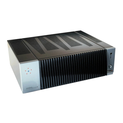
The 700:7r is a high-performance seven-
channel amplifier that delivers sound
reproduction of outstanding clarity and
purity together with the flexibility to handle a
wide range of home theatre applications.
The 700:7r provides seven channels of
100W into 8 Ohm (7.1 set-up), or can
be instantly switched to give five
channels of 100W and one channel of
150W (6.1 set-up), or three channels
of 100W and two channels of 150W
(5.1 set-up). For details see page 11.
5, 6 or 7 speaker system? All are catered for by the 700:7r.
The amplifier switches itself to a standby mode when not in use, to minimise power
consumption. It returns from standby to active on receiving a signal input or external contact
closure; alternatively it can be set to stay permanently in the active mode. For details see
page 15.
The 700:7r includes comprehensive but completely unobtrusive protection against overload,
excessively prolonged clipping, DC offsets, and high temperatures.
The seven channels could be assigned as:
GRR01030.02-UK-7007r.qxd 10/22/03 3:07 PM Page 04

technology|05
An Optimal Mix of Global and Local Negative Feedback
The 700:7r gives excellent linearity and low distortion without relying on excessive global
negative feedback, which can present difficulties with stability and the handling of rapidly-
changing signals. The 700:7r design is implemented by giving each amplifying stage
controlled amounts of local feedback, which not only linearises it but also defines the gain
and other vital parameters closely. Each stage is thus configured for dependable and
predictable operation, so that when they are joined together to build a complete amplifier,
and a carefully chosen amount of negative feedback applied around it, the results are highly
dependable and predictable.
Cascode Compensation
The 700:7r uses an advanced loop stabilisation concept called Cascode Compensation.
To the best of our knowledge TAG McLaren Audio is the only manufacturer to use this
sophisticated and elegant system in an audio amplifier.
Its advantages are as follows:
Excellent stability. All
the active components
involved are operated
under circuit conditions
that maximise their
bandwidth. This results
in greater stability
when the negative-
feedback loops are
closed.
Inherently good
supply-rail rejection.
Components that are
essential for power-
supply filtering in a
conventional amplifier
are no longer
required, saving
weight and cost and
enhancing reliability.
Reduction of DC drift. In a normal high-
power amplifier transistors in sensitive
parts of the circuitry get warm, which
means their characteristics vary depend-
ing on the air flow around them.
Variations in cooling can appear as DC
drift at the output. Cascode compensat-
ion transfers the heat dissipation to non-
critical parts of the circuit and DC drift
is virtually eliminated.
GRR01030.02-UK-7007r.qxd 10/22/03 3:07 PM Page 05

06 |technology
The Output Devices
The output devices are bipolar junction transistors chosen for maximum linearity in terms of
sustained current gain at high collector currents. The advanced MT-200 package is used
which gives a greater area for heat transfer than the traditional TO3. This reduces junction
temperatures and further enhances reliability.
Exceptional Quiescent Stability
It is universally accepted that accurate setting and stability of quiescent conditions is crucial
to optimal Class-B operation. The bias range over which the best linearity is obtained is
narrow, and on either side of it crossover distortion increases markedly. This consists of high-
order harmonics that are acknowledged by all as undesirable; it is therefore of the first
importance that an amplifier stays in its optimal bias range, despite the many varying
conditions it will face in operation.
The 700:7r has extremely accurate quiescent control. Quiescent conditions are stabilised
against:
Output level and load impedance changes
This is implemented by a unique sensing configuration that gives much faster and more
accurate assessment of output device junction temperatures than the conventional
methods.
Mains voltage changes
It is not widely known that changes in mains voltage can affect amplifier quiescent
conditions even if all of the small-signal and biasing circuitry is made immune to these
variations. The effect is subtle and complex, but is dealt with authoritatively by circuitry
unique to TAG McLaren Audio.
GRR01030.02-UK-7007r.qxd 10/22/03 3:07 PM Page 06

technology|07
Low distor tion
A theoretically ideal amplifier reproduces
sound perfectly over an infinite range of
frequencies - starting from well below the
audible range and extending far above the
capabilities of human hearing. Although
sound outside the human hearing range of
approximately 20 Hz to 20 kHz cannot be
heard, it can significantly distort the quality
of music reproduction through an effect
which audio engineers call
‘intermodulation distortion’. This type of
distortion moves imperfections that
originate outside the hearing range back
into the audible frequencies. To minimise
this effect, TAG
McLaren Audio
amplifiers have
a frequency
response
which
extends
both above
and below
the range of
normal human
hearing.
Comprehensive pr otection
The 700:7r has sophisticated and
dependable protection for both its own
circuitry and connected loudspeakers.
An instantaneous overload protection
system monitors the current and voltage
conditions in the output devices and limits
power dissipation in critical circumstances.
If the excessive loading persists, an
intelligent long-term protection algorithm
disconnects the load to prevent excessive
thermal stress which can shorten
component life.
Sophisticated muting
The 700:7r has a sophisticated muting
system, which stops you hearing loud,
annoying switching noises and protects
both the amplifier and the loudspeakers.
Particular care has been taken to make
sure that the muting circuitry, when
switched off, doesn’t affect the sound
quality. For this purpose carefully selected
relays with minimal crosstalk between coil
and contacts have been used.
GRR01030.02-UK-7007r.qxd 10/22/03 3:07 PM Page 07

08 |technology
Straight line technology
An amplifier must respond to very low
frequencies but block any Direct Current
(DC) to prevent intermodulation distortion.
This is traditionally achieved using
capacitors, which also block some of the
low-frequency signals. In the 700:7r a
feedback circuit eliminates DC offset
voltage and allows the signal path to be
direct coupled without any capacitors, an
arrangement called ‘straight line’
technology. The result is a very precise
reproduction of the lowest bass.
Supersonic frequency r esponse
In order to reproduce high frequencies, the
700:7r is constructed using highly-rated,
high-precision components. The circuit has
been painstakingly designed to minimise
audio signals picking up interference and
intermodulating. Exceptional transparency
and purity of sound are the result.
mixed technology construction
With surface mount components for fast
digital signal transfer and leaded through-
hole components for perfect audio signals,
the 700:7r incorporates mixed technology
construction to optimise performance. The
result is uncompromised sound in a small
size.
GRR01030.02-UK-7007r.qxd 10/22/03 3:07 PM Page 08

set-up|09
preparation
We know you are keen to get your 700:7r working. This section will have you
listening as quickly as possible. The controls diagrams located on pages 2 and 3
of this manual will help you find your way around your 700:7r(1).
safety first
To prevent the risk of electric shock follow
these instructions carefully. If in doubt
consult a qualified electrician
befor e you start
Make sure that all the components of your
system are disconnected from the AC supply
whenever you change any connection.
positioning
The 700:7r is capable of consuming
approx. 2000 Watts of electrical power
during demanding presentations. This results
in significant heat being dissipated.
1. Throughout this manual, bold print indicates the lettering that you will find on the rear panel of your 700:7r
• Please ensure that there is adequate
ventilation above and below the unit.
• The ventilation of the 700:7r should not
be impeded by covering the ventilation
slots with items such as newspapers, table
cloths, curtains etc.
• Place the 700:7r on an open flat surface.
• Do not use in a cabinet or on a soft
surface such as a carpet.
• Do not place any other piece of
equipment on top of the 700:7r.
• Do not place naked flame sources such as
lighted candles on the 700:7r.
• Do not expose the 700:7r to dripping or
splashing liquids.
• Do not place objects filled with liquids,
such as vases, on or near the 700:7r.
Make sure there is adequate ventilation for the amplifier. It is important that the cooling slots
in the top and bottom are not obstructed, and there is sufficient space around the unit to
allow for the free circulation of air. Avoid operating the amplifier on a soft surface, such as
thick carpet, which is likely to block the slots underneath,
GRR01030.02-UK-7007r.qxd 10/22/03 3:07 PM Page 09

10 |set-up
Before making any signal connections ensure the
amplifier is not connected to the mains supply.
remove power
loudspeaker connection
Ensure that the amplifier mains plug has been
removed from the wall socket before making
loudspeaker connections.
When making the connection, ensure that the spade
terminal is correctly located and the loudspeaker
terminal is fully tightened.
signal connection
Ensure that the amplifier mains plug has been
removed from the wall socket before making
loudspeaker connections.
Connect your pre amplifier/av processor using good
quality analog interconnects.
GRR01030.02-UK-7007r.qxd 10/22/03 3:07 PM Page 10

set-up |11
7channel set-up
You will find 7 pairs of loudspeaker terminals on the rear of the unit. For seven channel use,
the speakers are connected between the + (red) and -(black) terminals as shown above.
Connect the red (+) terminal of the loudspeaker to the red terminal on the rear panel of the
700:7r. In turn connect the black (–) terminal of the loudspeaker to the black terminal on the
700:7r.
For seven channel use the channel bridging switch is in
the ‘off’ position.
It is not advisable to change the position of this switch when the amplifier is powered and connected to loudspeakers. No damage to the
amplifier will result, but you may apply an unexpectedly high level to the loudspeakers.
GRR01030.02-UK-7007r.qxd 10/22/03 3:07 PM Page 11

12 |set-up
When the 700:7r is operated in bridged mode, two amplifier channels are used to drive
each loudspeaker, for greater power output.
To use bridged modes of operation you must alter the position of the channel bridging slide
switch on the rear of the unit. This has three positions and allows you to bridge just BR and
SR to give one extra-powerful channel, or bridge both BR-SR and BL-SL to give two extra-
powerful channels.
The operation of the LEFT, RIGHT and CENTRE channels is not affected.
The channel bridging switch is put in the middle position
marked “BR+SR”
When the BR and SR amplifiers are bridged,
the + lead of the speaker cable connects to
the BR+ output terminal, and the - lead of the
speaker cable connects to the SR+ output
terminal as shown.
To apply signal to the BR-SR bridged channel
use the upper RCA input (marked “In A”).
The lower RCA (SR in) is not used.
6 channel set-up
Bridging
It is not advisable to change the position of this switch when the amplifier is powered and connected to loudspeakers. No damage to the
amplifier will result, but you may apply an unexpectedly high level to the loudspeakers.
GRR01030.02-UK-7007r.qxd 10/22/03 3:07 PM Page 12

set-up |13
5 channel set-up
The channel bridging switch is put in the
right position marked “BR+SR BL+SL”
The BL and SL amplifiers are now also
bridged, and the + lead of the speaker
cable connects to the BL+ output terminal,
and the - lead of the speaker cable
connects to the SL+ output terminal, as
shown.
To apply signal to the BL-SL bridged
channel use the upper RCA input (marked
“In B”). The lower RCA (SL in) is not used.
To apply signal to the BR-SR bridged
channel use the upper RCA input (marked
“In A”). The lower RCA (SR in) is not used.
It is not advisable to change the position of this switch when the amplifier is powered and connected to loudspeakers. No damage to the
amplifier will result, but you may apply an unexpectedly high level to the loudspeakers.
GRR01030.02-UK-7007r.qxd 10/22/03 3:07 PM Page 13

14 |set-up
You will require an av processor, such as the AV32R or a preamplifier, such as the DPA32R
to provide the signals to drive the 700:7r.
Each output is connected the appropriate RCA input on the 700:7r.
To connect the source equipment to the 700:7r you should use a hi-quality, well screened
RCA-RCA audio cable, such as our RCA/RCA F3-10-ANA interconnect. All the RCA-RCA
cables should be arranged so they are bundled as closely together as possible, especially at
the rear of the amplifier. This minimises the chances of loops of cable picking up magnetic
fields and possibly degrading performance.
Before making signal connections make sure the av processor/preamplifier and
all connected source units, such as a CD player are switched off and their mains
plugs have been removed from the wall sockets.
When you have completed the set-up and have connected all cables between all components,
ensure that the volume control on the av processor/preamplifier is set to minimum.
av processor or preamplifier connection
GRR01030.02-UK-7007r.qxd 10/22/03 3:07 PM Page 14

operation |15
Connect the mains cable to the amplifier, and then switch on at the
wall socket. The blue power LED will glow dimly to indicate that
power is applied but the amplifier is in the standby state. In this
condition the loudspeakers are disconnected by the internal muting
relays and power is removed from the amplifier circuitry.
If the standby mode switch on the rear is set to ‘ALWAYS ON’
(rightmost position), then after a short delay the amplifier will go to
the active state and the blue power LED will glow brightly. In the two
other positions the amplifier will remain in standby until it receives
an audio signal of sufficient amplitude, or a contact closure is
connected to the rear jack socket. This switch may be freely
operated when the unit is powered.
power connection
If the standby mode switch on the rear is set to ‘NORMAL’ (middle
position) and there is no external contact closure (see page 16) then
the amplifier will remain in the standby state until an audio signal
that exceeds the threshold is applied to at least one of the seven
inputs. It will then enter the active state and the blue power LED will
glow brightly. The amplifier will remain active for 15 minutes after
all audio signals disappear and will then return to standby. This
delay period is to prevent the amplifier going to standby on brief
interruptions, eg while changing CDs.
Audio signal activation
GRR01030.02-UK-7007r.qxd 10/22/03 3:07 PM Page 15

16 |operation
If the standby mode switch on the rear is set to ‘LOW SENSITIVITY’
(leftmost position) then operation is as for high sensitivity except that
the incoming audio signal must be at a higher level before it will be
acted upon. This setting should be used in electrically noisy
environments if there are problems with spurious activation.
Contact closure activation
If a piece of equipment providing a contact closure is connected,
and active so that the contact is closed, then as above, after a short
delay the amplifier will go to the active state and the blue power
LED will glow brightly. A contact closure will always bring the
amplifier into the active mode, whatever the position of the standby
mode switch on the rear.
The contact closure is applied to the 700:7r via the 3.5mm jack
socket on the rear panel. The circuit between the tip and the sleeve
of the jack must be closed. A stereo 3.5mm jack (with tip, ring and
sleeve) can be used- the ring is not connected.
If it is desired to shorten the 15-minute delay before standby, moving the standby mode
switch to ‘ALWAYS ON’ and then back to one of the audio activation positions will cancel the
delay and if there is no signal present the amplifier will go immediately into standby. This
switch may be operated freely when the amplifier is powered and connected to
loudspeakers.
GRR01030.02-UK-7007r.qxd 10/22/03 3:07 PM Page 16

protection system |17
If the amplifier finds it necessary to protect
itself against abnormal conditions, then it
will go into the standby state, with the
loudspeakers disconnected and power
removed from the amplifiers.
It will then attempt to re-enter the active
state after a short delay. If the conditions
causing the protection to operate persist,
then on the third time it enters standby, the
amplifier will stay there indefinitely until
manually reset by removing and reinserting
the mains cable. There are several ways in
which the 700:7r will protect itself and the
loudspeakers connected to it, and the
700:7r will signal why it reverted to
standby by flashing the power LED a
certain number of times. More details on
this are given in the next section.
Protection modes:
Short-ter m overload pr otection
This is implemented by instantaneously by
sophisticated circuitry that assesses the
voltage, current, and power dissipation
conditions in the power output devices.
Long-ter m overload pr otection
Caused by sustained short-circuit, overload
or heavy clipping in any of the seven
amplifier channels. The unit will go into
standby.
After a few seconds the unit will attempt to
return to the active state. If the conditions
causing the protection to operate persist,
then after the third time the amplifier enters
standby, it will stay in that state until the
mains power is cycled by removing and
reinserting the mains cable. The cable must
be removed for at least one second to
ensure that the unit resets itself; if the power
LED has gone out then enough time has
elapsed.
Overload protection signal: Power LED dim
but gives one short flash of bright every 1
second.
Protection
GRR01030.02-UK-7007r.qxd 10/22/03 3:07 PM Page 17

18 |protection system
Overtemperatur e protection
Caused by overheating of either the internal heatsink or the mains transformer, as a result of
blocked ventilation slots or some other abnormal condition. The unit will go into standby. After
a few seconds the unit will attempt to return to the active state. If the conditions causing the
protection to operate persist, then after the third time the amplifier enters standby, it will stay in
that state until the mains power is cycled by removing and reinserting the mains cable. The
cable must be removed for at least one second to ensure that the unit resets itself; if the power
LED has gone out then enough time has elapsed.
NB: Even when the mains power is cycled the unit will not become active unless it has cooled
down sufficiently. Allow time for cooling.
Overtemperature signal: Power LED dim but gives two short flashes of bright every 1 second.
DC offset pr otection
Caused by internal amplifier error or fault or a large DC input signal. Unit will go into standby.
After a few seconds the unit will attempt to return to the active state; if it identifies the fault
again, it returns at once to standby without unmuting the amplifiers. If the conditions causing
the protection to operate persist, then after the third time the amplifier enters standby, it will
stay in that state until the mains power is cycled by removing and reinserting the mains cable.
The cable must be removed for at least one second to ensure that the unit resets itself; if the
power LED has gone out then enough time has elapsed.
DC offset protection signal: Power LED dim but gives three short flashes of bright every
1 second.
It is most unlikely you will ever see this indication; if you do unplug the amplifier at once and
arrange for it to be checked by competent service personnel.
GRR01030.02-UK-7007r.qxd 10/22/03 3:07 PM Page 18

running in and warming up |19
running in
Just like a high quality car, the performance
of your 700:7r will improve during the first
hours of operation. The electronic
components will then have reached and
settled down to near perfect specification.
war ming up
Every time you switch on your 700:7r the
performance will improve until the
components reach their optimum operating
temperature.
optimum per formance for many years
GRR01030.02-UK-7007r.qxd 10/22/03 3:07 PM Page 19

20 |care and maintenance
There is a fuse in the
power socket on the back
of your 700:7r. To change
the fuse, unplug the
power cable and carefully
pull out the fuse carrier
drawer(1). The fuse carrier contains a spare
fuse; this is the first one that you see when
you open the carrier. You cannot open the
fuse drawer while the plug is in the socket.
There are no user-serviceable parts inside
the 700:7r.
In order to maintain the appearance of
your 700:7r, you can clean it as follows:
• before cleaning always disconnect
your 700:7r from the AC supply;
• any grease or dirt on the case may be
removed with a soft, lint free dry cloth.
Do not use any other solutions. Do not
use water or any solvents or abrasives;
• take great care not to get any liquid
inside the case. If this happens, you
should have your 700:7r serviced.
fuses
service
cleaning
The only service you should do to your 700:7r is described on the previous page. All other
servicing should only be carried out by one of our authorised service agents.
If service is required, please contact your authorised TAG McLaren Audio retailer. If your
700:7r is still under guarantee, please refer to the guarantee card which gives you details on
how to claim against the guarantee.
Please keep the original packaging and use it whenever your 700:7r is transported.
1. You cannot open the fuse drawer while the plug is in the socket
GRR01030.02-UK-7007r.qxd 10/22/03 3:07 PM Page 20

technical data |21
Power output 7 x 100W into rated load impedance (8 Ohm)
or 5 x 100W and 1 x 150W (8 Ohm)
or 3 x 100W and 2 x 150W (8 Ohm)
Input for rated power 1.05 Vrms
Input impedance 47 KOhm
Gain +28.8 dB at 1 kHz
Signal to noise better than 90 dB (relative to 0 dBW) unweighted
Frequency response 1.5 Hz - 150 kHz
( -3 dB )
operating 10 - 35°C
temperature range
ac supply voltage 220 - 240 V (the voltage is marked on the rear of the product)
ac supply frequency 50 - 60 Hz, depending on country
dimensions 445 mm wide x 130 mm high x 340 mm deep (including feet, terminals and controls)
We reserve the right to alter design and specification without notice.
Specification may vary for different countries.
GRR01030.02-UK-7007r.qxd 10/22/03 3:07 PM Page 21
Table of contents
Other TAG MCLAREN AUDIO Amplifier manuals

TAG MCLAREN AUDIO
TAG MCLAREN AUDIO DPA32R User manual

TAG MCLAREN AUDIO
TAG MCLAREN AUDIO PPA20 User manual

TAG MCLAREN AUDIO
TAG MCLAREN AUDIO PA10 User manual

TAG MCLAREN AUDIO
TAG MCLAREN AUDIO 60P User manual

TAG MCLAREN AUDIO
TAG MCLAREN AUDIO 100P User manual

TAG MCLAREN AUDIO
TAG MCLAREN AUDIO PA20R SL User manual

TAG MCLAREN AUDIO
TAG MCLAREN AUDIO 100X5R User manual

TAG MCLAREN AUDIO
TAG MCLAREN AUDIO 250MR User manual

TAG MCLAREN AUDIO
TAG MCLAREN AUDIO 100 5R Series User manual

TAG MCLAREN AUDIO
TAG MCLAREN AUDIO F3 Series User manual