TAG MCLAREN AUDIO F3 Series User manual

input
selector knob headphone
socket
volume
knob power
button
record
selector knob
mute
LED
power
LED
cd tuner
INPUT RECORD VOLUME
aux
tape 1
tape 2
tape 3
aux tuner cd
tape 1
tape 2
tape 3
integrated amplifier 60i
ground
left
right
right
left
right
out 3 inout out in out in
left
left
right
left
right
serial
number
220-240V
~50-60Hz
Fuse: T2.5A L250V
integrated amplifier 60i
made in United Kingdom
OUTPUT in
POWER
AMP PRE
AMP
TAPE aux tuner cd
SOURCE
21in
fuse
carrier tape in/out
sockets
power amp input
sockets
loudspeaker
terminals input
sockets
preamplifier output
sockets
ac supply
socket ground
terminal
60i 1234567
02 welcome
08 key features
10 getting started
13 selecting an input
15 volume control
16 headphones
17 grounding
18 connecting loudspeakers
23 multiple amplifier systems
25 running in and warming up
26 care and maintenance
28 technical data
32 international standards
contents
Specification shown may vary for different countries
GRA00046.1-[CA]60i 12/03/01 12:06 Page 1

03
Now,this blend of talent and
expertise has been combined
with the award-winning
experience ofAudiolab to create
a company with a technical
advantage and access to
resources second-to-none in the
high end audio industry -
TAG McLarenAudio.
TAG McLarenAudio has been created with
one aim in mind:to produce the best high-
fidelity audio and audio-visual systems
available.Now the first fruits of that
alliance are ready – a unique new range of
audio products.
Throughout the F3 Series development
process,quality,performance and
reliability have been paramount,resulting
in unparalleled performance,operational
excellence and sheer listening pleasure.
celebrating a TAG McLaren victory
All TAG companies perpetually strive
for, and achieve,excellence and high-
performance in every area of their
business.
These qualities are demonstrated in the
fastidious standards that makeTAG Heuer
watches some of the world’s most
admired;in the teamwork that makesTAG
McLaren’s motor racing team one of the
most successful in Formula One;and in the
advanced electronics technology that
makesTAG Electronic Systems the first
choice for many Formula One constructors
and high-performance car makers.
Derek Scotland (on the left) – Technical Director
Peter Stevens – Chief Industrial Designer
Dr. Zucker – Chief Executive
welcome to a new partnership
..in hi-performance, hi-fidelity
GRA00046.1-[CA]60i 12/03/01 12:06 Page 3

We are convinced it will give you many hours of
listening pleasure.
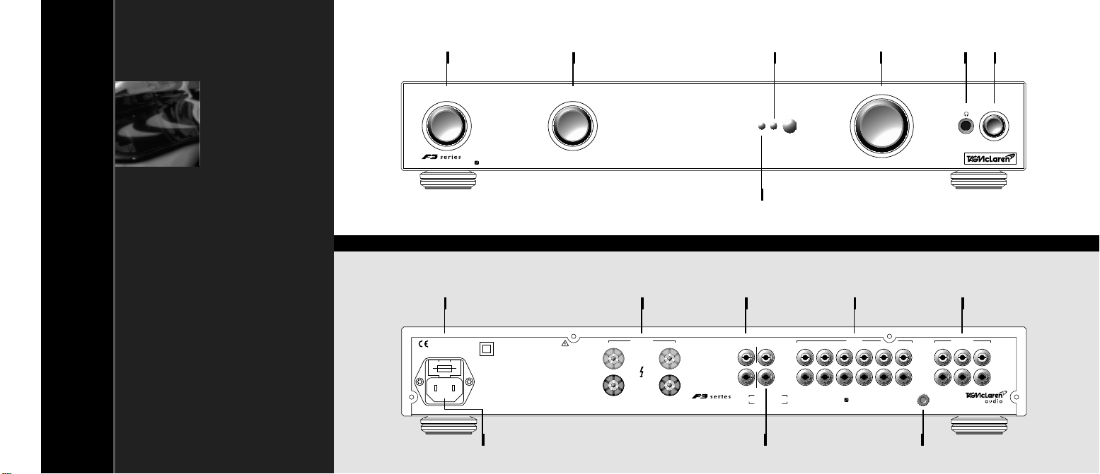
The 60i is an integrated amplifier,consisting of a preamplifier
and power amplifier connected together in the same unit.
Versatile input selector controls and a full-range volume control
enable the 60i to act as a total command centre for your audio
system.The 60i feeds plenty of undistorted power to your
loudspeakers to give you an outstanding listening experience.
versatile input
and recording selection
The 60i has six selectable inputs and three
outputs for recording.A separate signal
path is provided for recording,with its
own independent input selector,so you
can record one piece of music while
listening to another.
low intermodulation distortion
The theoretically-ideal amplifier
reproduces sound perfectly over an infinite
range of frequencies –starting from well
below the audible range and extending far
above the capabilities of human hearing.
Although sound outside the human hearing
range of approximately 20 to 20,000 Hz
cannot be heard,it can significantly distort
the quality of music reproduction through
an effect that audio engineers call
welcome welcome
050
Thank you for purchasing theTAG McLarenAudio integrated amplifier 60i.
‘intermodulation distortion’.This type
of distortion moves imperfections that
originate outside the hearing range back
into the audible frequencies.To minimise
this effect,TAG McLarenAudio amplifiers
have a frequency response which extends
both above and below the range of normal
human hearing.
exceptional low-frequency response
The 60i uses two different technologies
to achieve fidelity at low frequencies.
The preamplifier section uses capacitors
to block the unacceptable Direct Current
(DC) while allowing the desirable sound
signals to pass through unimpeded.TAG
McLarenAudio has expended many years
of design effort on the special circuitry
which, without compromising sound
quality, accommodates the high-quality,
integrated amplifier 60i
GRA00046.1-[CA]60i 12/03/01 12:06 Page 5

high weight of the 60i) and highly-specified
output circuitry.
future-proof
Although your 60i is an integrated
amplifier, a simple modification (which can
be arranged by your retailer) splits your
60i into separate preamplifier and power
amplifier sections.This allows you to
bi-amp,using a second power amplifier
(such as our 60P or 100P) or insert a signal
processor between the preamplifier and
power amplifier sections.
The 60i –an integrated amplifier with
uncompromised hi-performance
low-distortion capacitors that must
be used.
straight line technology
In the power amplifier section,a feedback
circuit eliminates DC offset voltage and
allows the signal path to be direct coupled
without any capacitors.This arrangement,
which we atTAG McLarenAudio call
‘Straight LineTechnology’, is easy to
describe but not easy to realise.The design
has taken our expert engineers years to
perfect.
supersonic high-frequency
response
In order to reproduce high frequencies,
the 60i is constructed using highly-rated,
high-precision components.The circuit has
been painstakingly designed to avoid any
possibility of signals picking up
interference and to minimise the effects
of intermodulation.
sophisticated muting
The 60i has a sophisticated muting system,
which stops you hearing loud, annoying
switching noises and protects the amplifier
and loudspeakers.
substantial power
The 60i’s power rating of 60 watts is very
conservative,as the 60i can typically
provide 72 watts into 8 Ω,115 watts into
4 Ω,and 150 watts into 2 Ωfor a short
period. Performance of this calibre is
essential to drive even the least sensitive
loudspeakers without distortion,and has
been achieved through the use of a very
large power supply (which accounts for the
welcome welcome
0706
GRA00046.1-[CA]60i 12/03/01 12:06 Page 7

‘Straight Line Technology‘ with direct coupled signal and
feedback paths
High-quality audio components
Rated 60 W, typically 72 W into 8 Ωcontinuous (rated 95 W,
typ. 115 W into 4 Ωand rated 130 W, typ. 150 W into 2 Ω
for short periods)
Mains supply interrupt monitor
Class A preamplifier stage
Optional separation of power and preamplifier sections
providing direct input to power amplifier section
Six line level inputs for: CD, tuner, auxiliary, and three
tape recorders
Independent input selection for listening and tape recording
Low-impedance stereo output from preamplifier to allow long
cable runs
Three stereo outputs for recording
Headphone output for a wide range of headphone impedance
with automatic muting when headphones are plugged in
Sorbothane®sonic isolation feet, specially designed by
TAG McLaren Audio(1)
•
•
•
•
•
•
•
•
•
•
•
•
08 09
key features key features
1. For the very best performance we recommend that our units are placed on
individual shelves and are not stacked one on top of another
GRA00046.1-[CA]60i 12/03/01 12:06 Page 9

We know you are keen to get your 60i working. This section will
have you listening to your favourite music as quickly as possible.
If you fold out the front cover of this manual you will locate
diagrams which will help you find your way around your 60i(1).
Make sure that all the components of your audio system are
disconnected from the AC supply whenever you change any
connections.
On the back of your 60i, you will find two pairs of loudspeaker
terminals, each pair consisting of one red and one black.
The terminals on the back of the 60i use BFA(2) sockets. The BFA
plug pushes into the middle of the terminal.
Use high-quality loudspeaker cable terminated in BFA plugs(3) to
connect the red(4) terminal of your right loudspeaker to the red
terminal marked OUTPUT right on the back of your 60i.
Then connect the black terminal of your right loudspeaker to the
black terminal marked OUTPUT right on the back of your 60i.
before
you start
loudspeaker
terminals
loudspeaker
connection
Connect the left loudspeaker to a pair of left terminals in the same way.
You will need a source of audio signals (such as our CD player
CD20R or our tuner T20) to feed into your 60i. Use a good-
quality, screened phono-phono audio cable to connect the phono
output sockets of your sound source to the appropriate pair of
left and right sockets marked SOURCE aux,tuner,cd or TAPE
in 1,in 2 or in 3 on the back of your 60i(6).
sound source
connection
10 11
getting started getting started
The diagram shows a
standard loudspeaker
arrangement(5)
1. Throughout this instruction manual (except in titles), bold print indicates the
lettering that you will find on the panels of your 60i
2. In models for countries where the AC supply is 115 V, the terminals accept 4 mm
‘banana‘plugs instead of BFA plugs. 4 mm plugs are not permitted in Europe.
Please see page 18 for more details of the terminals
3. If you prefer to use a cable which does not have BFA plugs, please see page 19
4. If your loudspeaker terminals are not colour coded –red corresponds to positive
(+) or signal and black corresponds to negative (-)
5. The diagram is for illustrative purposes only; it is not to scale and does not show
all connections. Please see page 18 for more details on connecting loudspeakers
6. The inputs for cd,tuner,aux,TAPE 1,TAPE 2 and TAPE 3 are all the same
electrically. They are named for your convenience
right speaker
lf outin
left speaker
GRA00046.1-[CA]60i 12/03/01 12:06 Page 11

power
connection
setting controls
switch on
Check that the power button is out so that power is off when you
plug in(1). Using the cable supplied, connect the socket on the
back of your 60i to an AC supply outlet. For the best sound
quality, we recommend that you do not use multi-plug adaptors.
Turn the VOLUME right down (all the way anticlockwise).
Set the INPUT selector to the input to which you connected your
sound source.
Press the power button in. The blue power LED will come on.
Wait for about 10 seconds until the mute LED on the front panel
goes out(2).
Start playing your sound source.
Turn up the VOLUME, sit back and enjoy the music.
12 13
getting started selecting an input
Your 60i has six line level inputs which can be selected by
name(1). The input for listening can be selected independently
from the input for recording so you can listen to one source and
record another at the same time.
The signal from your chosen input source will be amplified and
sent to the loudspeaker terminals, the headphone socket and the
preamplifier output. To select your source, turn the INPUT selector
until the mark on its side points to the name of the input that you
want to listen to.
inputs for
listening
1. The inputs for cd,tuner,aux,TAPE 1,TAPE 2 and TAPE 3 are all the same
electrically. They are named for your convenience
1. The power button is a latching switch. One press will hold it in, the next will
release it
2. The output is muted when the power is switched on to allow all the voltages to
stabilize. This protects your 60i and loudspeakers and prevents unpleasant
switching noises from upsetting your listening experience
cd tuner
INPUT
aux
tape 1
tape 2
tape 3
VOLUME
cd tuner
INPUT
aux
tape 1
tape 2
tape 3
GRA00046.1-[CA]60i 12/03/01 12:06 Page 13

The VOLUME knob alters the signal level of the loudspeaker
terminals, the headphone socket and the preamplifier output.
It does not affect the output from the record sockets (TAPE out 1,
out 2 and out 3).
Turn the VOLUME knob clockwise to increase volume and
anticlockwise to decrease volume. When supplied with an input
with a peak level of 2 V rms (the typical output from a CD
player), your 60i gives its full rated output with the VOLUME
knob in the middle of its travel. Turning the knob past this point
may distort the sound and could damage your loudspeakers.
An LED on the front panel indicates when the 60i is muted.
volume
mute
1 15
selecting an input volume control
1. The TAPE out 1,out 2 and out 3 sockets are connected together internally and
are identical electrically
2. A loop is created if a tape recorder output and input are both connected to your
60i and the same tape recorder is selected as the record input. This may cause
feedback if your recorder is set to record. To avoid this possibility, we
recommend that you select the input for recording before you set your recorder
to record
The signal from the input that you select for recording will be sent to
the record output sockets marked TAPE out 1, out 2 and out 3(1).
To select your source for recording, turn the RECORD selector until
the mark on its side points to the name of the input that you want
to record(2).
The record output is not affected by the muting or volume controls.
inputs for
recording
out 3 in out in out in
left
right
EP
TAPE
21in
VOLUME
RECORD
aux tuner cd
tape 1
tape 2
tape 3
Turn the VOLUME knob clockwise to increase volume and
anticlockwise to decrease volume. When supplied with an input
level of 2 V rms (the typical full scale output from a CD player),
your 60i gives it full rated output with the VOLUME knob in the
middle of its travel. Turning the knob past this point may distort
the sound and could damage your loudspeakers.
GRA00046.1-[CA]60i 12/03/01 12:06 Page 15

avoiding hum
grounding
your system
The AC mains supply normally operates at either 50 or 60 Hz
(depending on which country you are in). Under some
circumstances, this can cause an audible hum in your
loudspeakers.
Should you have any problems with hum in your system,
please contact your retailer.
To minimise the possibility of mains hum in your system:
do not link the ground terminals of separate audio units
together.
use screened cable for your signal connections and keep
the left and right channel cables close together.
All the units in the TAG McLaren Audio F3 Series are double
insulated and do not require safety ground connections.
Although a ground terminal is provided on the 60i, for your
convenience your system does not need to be connected to
ground (audio engineers call this ‘floating‘). However, if you want
to ground your system, please contact your retailer who will be
able to assist you.
headphone
connection
loudspeaker
muting
Turn the VOLUME down before you connect your headphones.
Insert the headphone plug into the 1/
4”(6.3 mm) stereo jack socket
on the front panel of your 60i(1).
When you plug in your headphones, the loudspeaker and
preamplifier outputs are automatically muted(2).
16 17
headphones grounding
1. If you want to use headphones which have the smaller 1/8”(3.2 mm) jack plug,
you should obtain an adaptor from your retailer. Remove the adaptor from the
socket when you are not using the headphones or the output will remain muted
2. If the 60i has been modified to disconnect the preamplifier from the power
amplifier (see page 23), then plugging in headphones also isolates the power
amplifier input
GRA00046.1-[CA]60i 12/03/01 12:06 Page 17

The connection between your 60i and your loudspeakers
is crucial to the sound quality of your entire audio system.
Please follow these recommendations to achieve the best results.
Your 60i is specified to operate with 8 Ωloudspeakers, but it can
be used with 4 Ωloudspeakers. The 60i may also be connected
to loudspeakers which have a transient impedance of less than
4 Ω(1).
Always switch off your 60i before changing any connections.
Always use high-quality loudspeaker cable.
On the back of your 60i, you will find two pairs of loudspeaker
terminals, each pair consisting of one red and one black terminal.
We recommend that you use loudspeaker cables terminated in
BFA plugs or spade terminals. These plugs are designed to fit the
terminals on the back of the 60i(1). The BFA plug and socket
ensures that you cannot touch the high-voltage output conductors.
Screw the knob of the terminal all the way in and push the plug
into the centre of the knob.
If you do not have BFA plugs, you can use ‘spade’connectors.
Unscrew the terminal enough to push the spade into the slot in the
side of the terminal, then tighten the terminal by hand. You should
not use tools to tighten the terminal; over-tightening will reduce
the sound quality.
If you choose to use bare wire, there is a hole in the side of the
terminal to accommodate it. Make sure that there are no strands
of wire sticking out of the terminal.
loudspeaker
terminals
18 19
connecting loudspeakers connecting loudspeakers
connection
methods
right left
OUTPUT
1. The BFA connector complies with current EU safety standards, which do not
allow the use of 4 mm ‘banana‘plugs. 4 mm terminals are permitted (and are
fitted to the 60i) in countries where the AC supply is 115 volts
1. These ratings are for music signals only. If the 60i is amplifying a continuous
sine wave, an 8 Ωload must be used
GRA00046.1-[CA]60i 12/03/01 12:06 Page 19

With many high-quality loudspeakers, you can make separate
connections to the high- and low-frequency drivers(1). In such
cases, you may want to run separate cables for the high and low
frequencies as shown in the diagram. To do this, you will need to
remove the links, provided as part of the loudspeaker, which
connect the drivers. Please refer to your loudspeaker instructions
to find out how to do this.
Bi-wiring provides separate paths for high- and low-frequency
signals, improving the sound quality in many cases.
bi-wiring
1. The ‘driver’is the mechanism inside the case of the loudspeaker which actually
makes the sound. Most high-quality loudspeakers have drivers for high, low and
often middle frequencies and the capability to connect them separately.
However, the lack of this facility is not necessarily a sign of low quality (as some
of the finest loudspeakers in the world have proved)
This diagram shows
a 60i bi-wired to
loudspeakers
standard
connection
The simplest way to connect your loudspeakers is to run a single
cable (consisting of two wires) to each one. For each stereo
channel connect the red terminal on the speaker to the red
terminal on the 60i labelled OUTPUT Repeat for the black
terminals(1).
If your loudspeaker has separate connections for high and low
frequencies, make sure these are linked together.
1. Connecting black to black and red to red ensures that the ‘phasing’is correct. If
this is wrong it can affect the sound. If your loudspeaker terminals are not colour-
coded, black corresponds to negative (-) and red corresponds to positive (+) or
signal. Please refer to your loudspeaker manual for details
2. This diagram, and those that follow, are for illustrative purposes only; they are
not to scale and do not show all connections
This diagram shows a
60i connected to
loudspeakers with a
single input(2)
connecting loudspeakers
20
connecting loudspeakers
21
right speaker
hf
lf outin
hf
lf
left speaker
right speaker
hf
lf outin
hf
lf
left speaker
GRA00046.1-[CA]60i 12/03/01 12:06 Page 21

Your 60i is designed to be used as an integrated amplifier.
However, the following facilities have been provided to allow you
to use the 60i with other amplifiers if you wish.
If you want to expand your audio system, please contact your
retailer who will be happy to discuss your specific requirements.
The output of the preamplifier section is brought out to the
PREAMP out sockets on the back panel and can be connected to
an external stereo power amplifier (such as our 100P) or to a pair
of monobloc(1) power amplifiers (such as our 125M). The 60i can
be used as a stand-alone preamplifier or it can form part of a bi-
amp system in which its built-in power amplifier is used in
conjunction with another, external power amplifier, allowing the
high- and low-frequency drivers in each loudspeaker to be
powered separately.
output from
preamplifier
If you wish to do this, you will need to connect two wires to one
terminal. We recommend that you use stackable BFA plugs for
this purpose. These are available from your retailer.
bi-wiring
connecting loudspeakers
22
multiple amplifier systems
23
1. A ‘monobloc’is a single-channel or mono power amplifier
GRA00046.1-[CA]60i 12/03/01 12:06 Page 23

TAG McLaren Audio equipment is designed to give optimum
performance for many years.
Just like a high-quality car, the performance of your 60i will
improve during the first few hours of operation. The electronic
components will then have reached and settled down to near-
perfect specification.
Every time you switch on your 60i, the performance will improve
until the components reach their optimum operating temperature.
running in
warming up
The 60i consists of a preamplifier and a power amplifier inside
the same unit. The output of the preamplifier is normally
connected internally to the input of the power amplifier, in which
case the sockets labelled POWER AMP in are not connected.
Some multiple amplifier configurations require the internal link
between the preamplifier and the power amplifier to be
disconnected. Your retailer can arrange this. When the
modification is carried out the sockets labelled POWER AMP in
become the input to the power amplifier. With the 60i modified in
this way you can also connect a signal processor between the
preamplifier and power amplifier sections.
When you use the preamplifier output of your 60i to drive other
equipment, switch the power on and off in the following order:
Switch on the 60i first
Switch off the 60i last
input to power
amplifier
switching on a
multi amplifier
system
multiple amplifier systems
2 25
running in and warming up
GRA00046.1-[CA]60i 12/03/01 12:06 Page 25

service The only service you should do to your 60i is described on the
left. All other servicing should only be carried out by one of our
authorised service agents.
If service is required, please contact your authorised TAG
McLaren Audio retailer. If your 60i is still under guarantee, please
refer to the guarantee card which gives you details on how to
claim against the guarantee.
Please keep the original packaging and use it whenever your 60i
is transported.
There is a fuse in the power socket on the back of your 60i.
To change the fuse, unplug the power cable and pull out the fuse
carrier drawer(1).
The fuse carrier contains a spare fuse; this is the first one that you
see when you open the carrier.
There are no other user-serviceable parts inside the 60i.
In order to maintain the appearance of your 60i, you can clean
it as follows:
before cleaning, always disconnect your 60i from the AC
supply.
any grease or dirt on the case may be removed with a soft,
lint-free cloth moistened slightly with a mild solution of warm
water and detergent or washing-up liquid. Do not use any
other solutions. Do not use any solvents or abrasives.
take great care not to get any liquid inside the case.
If this happens, you should have your 60i serviced.
fuses
cleaning
1. You cannot open the fuse carrier drawer while the plug is in the socket
care and maintenance
26 27
care and maintenance
GRA00046.1-[CA]60i 12/03/01 12:06 Page 27

29
technical data
technical data
28
100 Ωnominal
greater than 7.76 V rms
1kΩnominal
0 dB (i.e. the record output level is the same as the input level)
47 kΩnominal
782 mV rms (for full rated output)
29.0 dB at 1 kHz
power amplifier
gain
preamplifier
signal to noise
preamplifier gain
60 W per channel into rated load impedance (8 Ω)
95 W into 4 Ωand 130 W into 2 Ωfor short periods
72 W per channel into rated load impedance (8 Ω)
115 W into 4 Ωand 150 W into 2 Ωfor short periods
30 kΩnominal
175 mV rms
(relative to 0.5 V rms preamplifier output)
9 dB at 1kHz
greater than 80 dB
(relative to 0.5 V rms preamplifier output)
preamplifier
input level
preamplifier
input impedance
rated output
power
(both channels driven)
typical output
power
(both channels driven)
This section is for those of you who really want to know the
‘insides‘of your 60i. You will not miss out on any of the functions
or performance of your 60i if you choose not to read any further.
preamplifier output
impedance
preamplifier
maximum output
record output
impedance
record output gain
power amplifier
input impedance
power amplifier
input level
GRA00046.1-[CA]60i 12/03/01 12:06 Page 29

31
technical data
technical data
30
10 –35 ˚C
50 –60 Hz
110 –120 V or 220 –240 V
The voltage is marked on the rear of the unit
less than 300 W
445 mm wide
75 mm high
350 mm deep
ac supply
frequency
ac supply
voltage
power
consumption
operating
temperature range
crosstalk rejection
channel separation
polarity (phase)
greater than 80 dB (relative to 0 dBW)
1Hz–65 kHz
± 0.5 dB
less than 0.07%
greater than 60 dB at 1kHz
greater than 80 dB at 1kHz
non-inverting for all inputs and outputs
330 Ω(suitable for headphones of 8 Ω–2 kΩimpedance)
total harmonic
distortion +noise
dimensions
(including feet,
terminals and controls)
We reserve the right to alter design and specification without notice
Specification may vary for different countries
frequency response
(-3 dB)
frequency response
(20 Hz –20 kHz)
headphone output
impedance
power amplifier
signal to noise
The rated and typical performance applies when the mains supply voltage is either
230 V AC for 220 - 240 V units or 115 V AC for 110 - 120 V units
GRA00046.1-[CA]60i 12/03/01 12:06 Page 31

international standards
32
*115 V units are fitted with 4 mm terminals. They comply with 73/23/EEC, IEC65 and EN60065 in all other aspects
Your 60i meets or exceeds all the legal requirements listed below:
directives
safety
emc emmissions
emc immunity
89/336/EEC EMC Directive (as amended by 93/23/EEC)
*73/23/EEC Low Voltage Directive (as amended by 93/23/EEC)
* IEC65: 1985
* IEC65 A2: 1989
* IEC65 A3: 1992
* EN60065: 1993
EN50081-1: 1992
EN55022 Class B: 1994
EN60555 -2: 1987
EN61000 -3-3: 1995
FCC Part 15 Class B: 1997
EN50082 -1: 1992
IEC801 -2: 1991 ± 8 kV air discharge
IEC801 -3: 1984 3 V/m
IEC801 -4: 1988 ± 1 kV AC power, ± 500 V other ports
EN61000 -4-2: 1995 ± 8 kV air, ± 4 kV contact discharge
EN61000 -4-4: 1995 ± 1 kV AC power, ± 500 V other ports
EN61000 -4-5: 1995 ± 2 kV common mode, ± 1 kV differential mode
EN61000 -4-11: 1994
GRA00046.1-[CA]60i 12/03/01 12:06 Page 33
This manual suits for next models
1
Table of contents
Other TAG MCLAREN AUDIO Amplifier manuals

TAG MCLAREN AUDIO
TAG MCLAREN AUDIO 60P User manual

TAG MCLAREN AUDIO
TAG MCLAREN AUDIO 60IRV User manual

TAG MCLAREN AUDIO
TAG MCLAREN AUDIO 100X5R User manual

TAG MCLAREN AUDIO
TAG MCLAREN AUDIO DPA32R User manual

TAG MCLAREN AUDIO
TAG MCLAREN AUDIO 125M User manual

TAG MCLAREN AUDIO
TAG MCLAREN AUDIO 700:7r User manual

TAG MCLAREN AUDIO
TAG MCLAREN AUDIO PA20R SL User manual

TAG MCLAREN AUDIO
TAG MCLAREN AUDIO 100P User manual

TAG MCLAREN AUDIO
TAG MCLAREN AUDIO PPA20 User manual

TAG MCLAREN AUDIO
TAG MCLAREN AUDIO AvantGarde 100X5R:10 User manual