Tait TMAA11-01 User manual

© Tait Limited December 2016
www.taitradio.com
402-00052-04
TMAA11-07/TMAA11-08
Extended Dual Head Upgrade Kits
Installation Instructions
Introduction
The TMAA11-07 or TMAA11-08 upgrade kit can be used to convert a TM8250 or TM8255
mobile radio (single radio body and graphical-display control head) to a dual-head radio
system. In a dual-head radio system, elements of the user interface (such as display content,
internal speaker audio, and LEDs) are duplicated on both control heads. This enables
multiple users to share the same radio.
In addition, the upgrade kit allows one or both control heads to be installed away from the
radio body in difficult or isolated locations, up to a maximum 1km. The kit includes a
transmit/receive pair of extender boxes to provide the necessary processing and protection
of signals over longer distances, and a control-head interface box to locally re-power one
or both control heads.
The upgrade kits provide the following items:
In addition to the items in this kit, you also require two matching lengths of crossover
network cable up to 1km each. The cable may be a combination of structured cabling, patch
cables and adaptors. The crossover configuration must be a two-pair crossover, wired 1-3,
2-6, 3-1, 4-4, 5-5, 6-2, 7-7, 8-8 (as per TIA/EIA T568A and T568B).
If using off-the-shelf crossover cables or adapters, be aware that some are four-pair cross-
over and are therefore unsuitable. If using existing building network wiring, ensure there
is no other hardware in the circuit such as routers or switches.
You also need suitable equipment to connect the control-head interface box to a power
supply (such as a power cable assembly (IPN: 219-02883-00), or a power adaptor rated to
provide 10.8–16V DC at > 2A (IPN: 009-0001x-00, where x is 4 to 7 depending on
region)).
control-head remote interface
control-head U-bracket
cables:
■remote cable (x1)
■neck cable (x2)
body remote
interface
(multi-head)
extender box (x2)
Not Illustrated: cable grommets (x4), and extender/interface box washers and screws
control-head interface box

2TMAA11-07/TMAA11-08 Extended Dual Head Upgrade Kits
© Tait Limited December 2016
The kit is designed to upgrade either a new radio (not installed), an installed radio with
a head mounted locally, or a standard remote installation using TMAA03-16. If upgrad-
ing a standard remote installation, the existing head and body remote interfaces and
remote cable do not support extended distances and must not be re-used for the upgrade.
Refer to the radio installation guide for further information such as mounting the radio body
using the U-bracket, installing the antenna, and radio body power connections.
Installation Precautions
Warning Mount these products securely. Unsecured radio equipment is danger-
ous to radio users, and others.
Notice When drilling holes in a vehicle, check that drilling at the selected points will
not damage existing wiring, petrol tanks, fuel lines, brake pipes or battery cables.
Notice This equipment contains devices that are susceptible to static charges. The pro-
cedures outlined in this installation guide should therefore be carried out in a static-safe
environment. You can obtain information on antistatic precautions and the dangers of
electrostatic discharge (ESD) from standards such as ESD S4.1-1997 (revised) or BS EN
100015-4 1994. The Electrostatic Discharge Association website is
http://www.esda.org/.
Installation
The following diagram summarises how the components are installed. The items named or
shown in bold are part of the upgrade kit. A symbol means an RS485 terminating
resistor is fitted. Cable lengths indicate maximum cable lengths allowed and therefore the
maximum distance between components.

TMAA11-07/TMAA11-08 Extended Dual Head Upgrade Kits 3
© Tait Limited December 2016
1 Upgrade firmware in the existing radio and enable the software feature.
Check that the firmware version of the existing radio matches the control head supplied in
the kit. If not, upgrade the existing radio. For more information, click the Help [?] button
from the programming application’s Download dialog (Tools > Download).
Check that the radio body has the software feature for Multi-Head Support enabled (default
factory configuration). For more information, click the Help button from the programming
application’s Optional Features dialog (Tools > Optional Features).
to antenna
to power supply
to remote speaker (optional)
to external I/O (optional)
radio body
0.6m
neck cable
(SYSTEM)
existing control head
0.6m neck
cable
(SYSTEM)
remote
interface
for primary
control-head
(TMAA03-03C)
body remote
interface
(TMAC34-0T)
6m
remote
cable
(HEAD 2)
extender box
(T02-00088-CAAA,
head-end)
extender box
(T02-00088-CAAA,
radio-end)
control-head
interface box
(T02-00088-
AAAA, local
powered)
<1km crossover
network cable
(AUDIO)
<1km crossover
network cable
(DATA)
to
power
supply
Alternative
configuration
second control head
and remote interface
(TMAC42-0T01)
6m remote
cable

4TMAA11-07/TMAA11-08 Extended Dual Head Upgrade Kits
© Tait Limited December 2016
2 Uninstall the existing radio.
One or more of the following steps may not be necessary depending on the type and degree
of the existing installation.
a Remove the radio from its mounting position.
b Disconnect the cables from the rear of the radio, such as the power and antenna
cables.
c If upgrading a standard remote installation:
■disconnect, remove and discard the remote cable.
■remove and discard the control-head remote interface.
d Remove the control head (if upgrading a local
installation) or body remote interface (if upgrad-
ing a standard remote installation) from the
radio body. Use a 5mm (3/16in.) flat-bladed
screwdriver in the positions shown.
e Unplug the loom from the radio body.
f If upgrading a standard remote installation, dis-
card the existing body remote interface.
There are several remote interfaces available that are similar in appearance, but are con-
figured differently and serve different purposes. It is important that you only use the com-
ponents supplied in this kit for extended remote installations.
3 Assemble the remote interfaces.
a Assemble the body remote interface
(TMAC34-0T) to the radio body. Ensure the
earthing tag is attached as shown.
b Assemble the remote-interface for the primary
control head (TMAA03-03C) to the existing
head.
For more information, refer to the remote control-head installation instructionsa.
4 Configure the extender box and control-head interface box links.
a Remove the seals from the top of the extender and control-head interface boxes.
b Compare the link configurations with the label diagrams. Re-configure if necessary
using small long-nose pliers (or similar).
■One extender box must be configured as RADIO.
■One extender box must be configured as CONTROL HEAD.
■The control-head interface box must be configured as LOCAL POWERED.
c Mark the applicable diagrams on the extender and control-head interface box labels
(for identification purposes during the installation), and replace the seals.
a. IPN 402-00020-xx, available from
http://support.taitradio.com
.
lever point
seal
indication of
lever point

TMAA11-07/TMAA11-08 Extended Dual Head Upgrade Kits 5
© Tait Limited December 2016
5 Install the components and prepare the network cables.
a Mount or re-mount the radio body using the preferred method, such as U-bracket,
slide-in cradle, or security bracket. Refer to the relevant sections in the installation
guide, or the installation instructions included with the mounting kit.
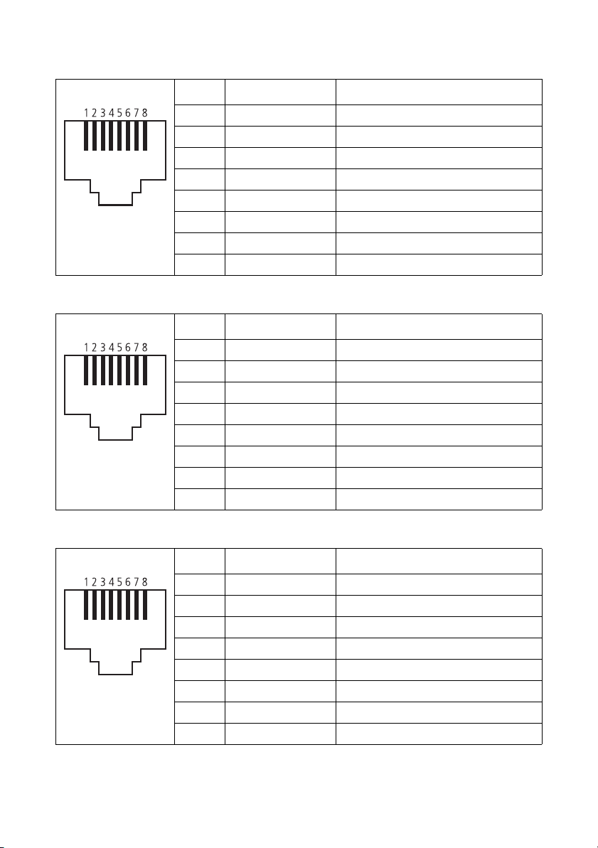
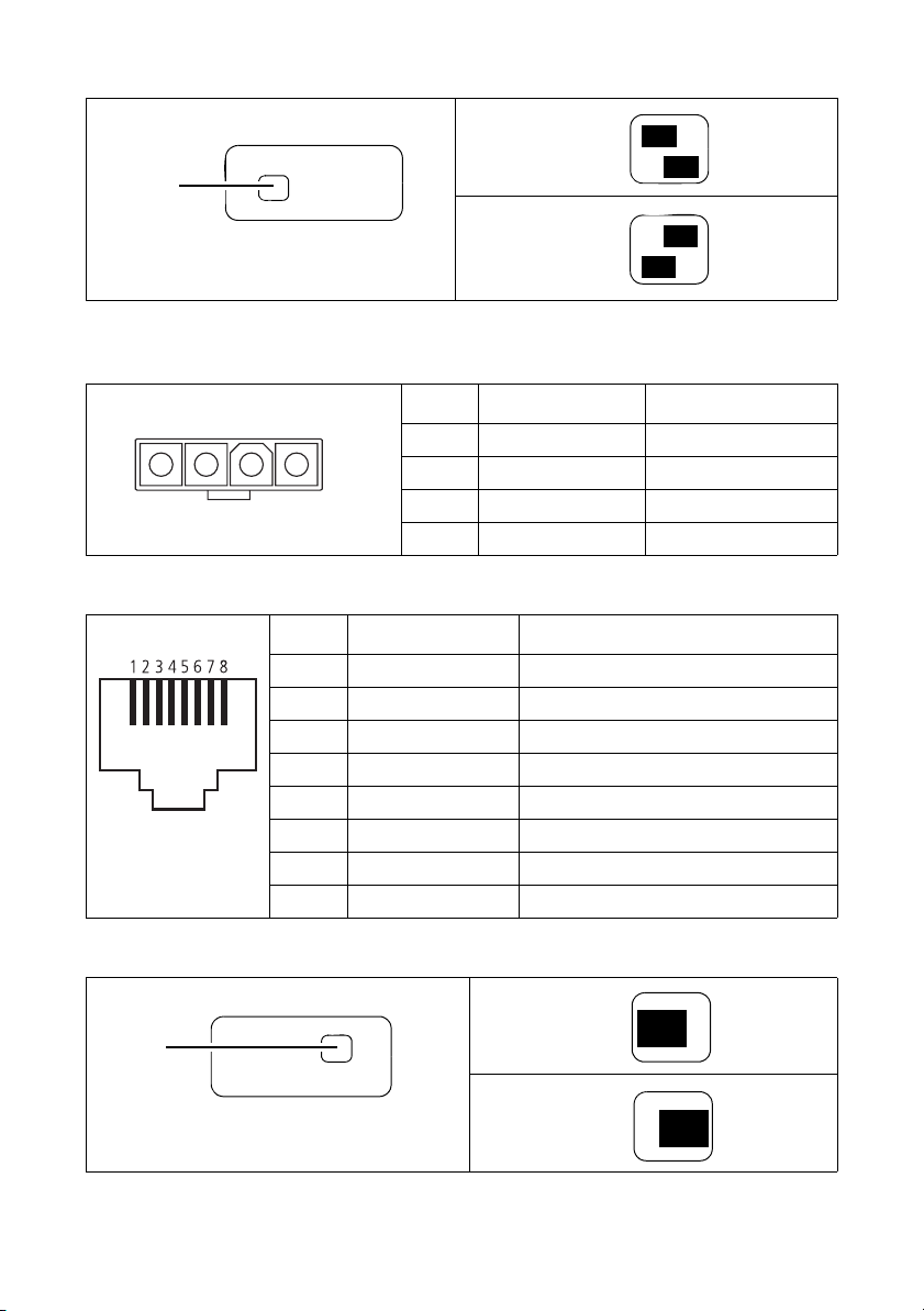
b Prepare the crossover network cables. Before crimping the RJ45 connectors, slide on
the grommets provided for strain relief (recommended). Make sure the cabling has a
direct path and is not interrupted by network devices such as switches or routers.
Refer to
page 7
for connector pins and signals.
c Lay out all cables as per the diagram on
page 3
. Determine the best mounting position
for all components, at distances less than the length of each cable used.
Notice The extender boxes and control-head interface box do not provide IP54 pro-
tection. Choose a mounting position away from water, dust, and other environmental
hazards.
d Use the washers and screws provided to mount the radio-end extender box, the head-
end extender box, and the control-head interface box.
Use the remote U-brackets and screws provided to mount the control heads. Refer to the
remote control-head installation instructionsb.
6 Install the cables.
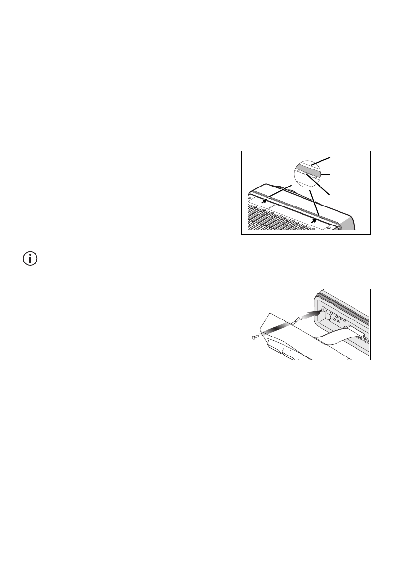
a Remove the innermost connector seal from the body remote interface, and
the outermost seal if required (see step g).
b Drill any holes required for the cables and install suitable grommets or bushings in the
holes.
c Use a neck cable to connect the
SYSTEM
socket of the radio-end extender box to the
innermost RJ45 socket of the body remote interface.
d Use crossover network cable to connect the
AUDIO
socket of the radio-end extender
box to the
AUDIO
socket of the head-end extender box.
e Use crossover network cable to connect the
DATA
socket of the radio-end extender
box to the
DATA
socket of the head-end extender box.
f Use a neck cable to connect the
SYSTEM
socket of the head-end extender box to the
SYSTEM
socket of the control-head interface box.
g Use one of the remote cables to connect the rear RJ45 socket of the primary control
head (see note below) to either:
■the remaining (outermost) socket of the body remote interface, or
■the HEAD 1 socket of the control-head interface box (alterative configuration).
See the diagram on page 3 for more information.
b. IPN 402-00020-xx, available from
http://support.taitradio.com
.

6TMAA11-07/TMAA11-08 Extended Dual Head Upgrade Kits
© Tait Limited December 2016
The control head with the lower MAC address is the primary head (the existing head by
default). The primary head adjusts remote-speaker volume (if a remote speaker is
attached), and must be used to re-program the radio system and upgrade firmware.
h Use the other remote cable to connect the rear RJ45 socket of the secondary control
head to the
HEAD 2
socket of the control-head interface box.
i Install all cable grommets. Ensure each grommet is seated correctly.
7 Connect power to the control-head interface box.
The control heads, when installed over extended distances, must be powered locally using
the control-head interface box. Select from one of the following power options:
Notice First, make sure the chosen power option is disconnected at the source.
■
Use the power cable assembly (IPN: 219-02883-00) to connect the power connector
( ) to a power source such as a vehicle battery (refer to the radio installation
guide), or to a TMAA12 or TMAA13 power supply. The red wire of the power cable is
positive.
■Use a power adaptor rated to provide 10.8–16V DC at >2A to connect the 2.5mm DC
jack to a power source.
Notice Power can be permanently applied to the interface box without affecting cur-
rent drain. The control heads will only power on when power is applied to the radio sys-
tem via the radio body.
8 Check the installation.
Apply power to the control-head interface box, then the radio body. If the radio does not
power on, press the On/Off key on one of the control heads. Check that both heads sound
the power-up tone and both displays are showing the same information.
If a “Duplicate MAC Address” message appears, you must uninstall the radio to a single-
head system and use the programming application’s multiple device configuration utility to
change the MAC addresses (click Tools > Multiple Device Configuration). For more
information, refer to the online help from within the utility (Help > Contents and Index).
9 Program the radio system.
a Connect the microphone socket of the primary control head to your PC, and apply
power to the radio system.
b Read the existing programming database, or open the programming file for the radio.
c Change settings as required. Select the Multi Head Info menu option (located on the
Menu form(s) under Radio Settings > Radio Information). Select the Listen In check
box (UI Preferences form) for microphone audio from a transmitting control head to
be routed to the speaker of the other control head.
d Click Radio > Program to program all devices in the system.
More Information
Refer to your radio provider for more information about this product.

TMAA11-07/TMAA11-08 Extended Dual Head Upgrade Kits 7
© Tait Limited December 2016
Extender Box Reference
Socket S201 (‘SYSTEM’)—pins and signals
Pin Signal name Description
1 RD_RX_AUD Receive audio
2 RD_13V8_SW Switched 13V8 supply from radio
3 RD_RS485+ Data
4 AGND Analog ground
5 MIC_AUD Microphone audio
6 RD_RS485- Data
7 DGND Digital ground
8 RD_CHC_ON_OFF Radio control head on/off
Socket S202 (‘AUDIO’)—pins and signals
Pin Signal name Description
1 SEND+ Send audio
2 SEND- Send audio
3 REC+ Receive audio
4 DGND Digital ground
5 RD_CH_ON_OFF Radio control head on/off
6 REC- Receive audio
7 AGND Analog ground
8 AGND Analog ground
Socket S203 (‘DATA’)—pins and signals
Pin Signal name Description
1 13V8_SW Switched 13V8 supply from radio
2 DGND Digital ground
3 13V8_SW Switched 13V8 supply from radio
4 DGND Digital ground
5 RD_ON_OFF Radio control head on/off
6 DGND Digital ground
7 RS485+ Data
8 RS485- Data
front view
front view
front view

8TMAA11-07/TMAA11-08 Extended Dual Head Upgrade Kits
© Tait Limited December 2016
Control Head Interface Box Reference
Extender Box Links
Power connector PL100—pins and signals
Pin Signal name Description
1 AGND Analog ground
2 N/C Not used
3 N/C Not used
4 +13V8 BATT 13V8 power input
Socket S201 (‘SYSTEM’)—pins and signals
Pin Signal name Description
1 RD_RX_AUD Receive audio
2 RD_13V8_SW Switched 13V8 supply from radio
3 RD_RS485+ Data
4 AGND Analog ground
5 MIC_AUD Microphone audio
6 RD_RS485- Data
7 DGND Digital ground
8 RD_CHC_ON_OFF Radio control head on/off
Control Head Interface Box Links
System
Audio Data
Link
location
● ● ●
●● ●
Radio end
●● ●
● ● ●
Control-
head end
1 2 3 4
rear view
front view
SystemHead 1 Head 2
Link
location
● ● ●
Radio
powered
●● ●
Local
powered
This manual suits for next models
1
Table of contents
Other Tait Transmitter manuals
Popular Transmitter manuals by other brands

ACS contsys
ACS contsys Sonicont USN020 manual

RHEONIK
RHEONIK RHE16 Short manual

Texmate
Texmate TL-QUAD-LOOP instruction manual

Teledyne Analytical Instruments
Teledyne Analytical Instruments LXT-380 instructions

RKI Instruments
RKI Instruments 65-2643XL0504SS Operator's manual

NVT
NVT NV-ET1804 installation guide