Takenaka System FS5100SPL User manual

N08A29;1/33
- 1 -
Video Camera
Instruction Manual
5 Megapixel Progressive Scan color Camera
FS5100SPL
●We greatly appreciate your confidence choosing our TAKEX CCD Video Camera.
●Please read this manual and the attached guarantee certificate carefully and manage the camera properly.
Keep this manual at hand and reread it whenever you are uncertain about the operation.
Table of Contents
1.
Features······························································································ 3
2.
Outline································································································· 3
3.
Description of Each Component ······························································· 4
4.
How to Operate····················································································· 6
5.
Various Settings ···················································································11
6.
How to Change Setting··········································································14
7.
Serial Communication Control·································································23
8.
Timing Chart························································································29
9.
Notes·································································································32
10.
Specifications·······················································································32
11.
External Dimensions ·············································································33
TAKENAKA SYSTEM CO., LTD
Document No.: N08A29
FS5100SPL Instruction Manual (2nd version)

N08A29;2/33
- 2 -
[History of revision]
Version Content of change Description Date Document
No. Remark
1st version - 2008-04-23 N08423 FS5100SPL
2nd version
Dimensional outline drawing
2008-07-14 K08A29
Description of special remarks used in this manual
(Note)················Particulars which require the user’s attention are explained.
(!)················Particulars which require the user’s close attention in terms of comparison with the conventional
products are explained.
[Terminology]················Terms specifically defined for the purpose of describing the operation of this camera are explained.
[Explanation]················Particulars for which details may be needed for user’s understanding of the operation of this
camera are explained.

N08A29;3/33
- 3 -
1. Features
●
FS5100SPL is a full frame shutter color camera incorporated with 5 megapixel, 2/3”-size CCD image sensor.
●
Power delivery, image data transmission and camera control are performed using single cable by adopting Power over
Camera Link (PoCL).
●
Single port CCD prevents the occurrence of level difference in brightness between right and left image.
●
A high-resolution full frame shutter color image can be obtained when used in combination with the capture board
equipped with color conversion function (Bayer-to-RGB conversion).
●
A full frame shutter image can be obtained at a rate of 9 frames per second.
●
8 or 10 bit digital image signal output complying with Camera Link (Base Configuration).
●
The internally set values of the camera can be externally controlled with serial communication via Camera Link.
●
The character information of the current setting status of the camera can be superimposed over the captured image on
the screen. (On Screen Display function)
●
The monitoring function for measuring the internal temperature.
●
The asynchronous shutter is applicable both in the preset shutter mode and the pulse width control mode.
●
The camera is designed so that the strobe signal can be output even in the continuous shutter mode, and this
contributes to the power saving for LED lighting and others as well as the reduction of smear.
●
The ID information set by the user for each camera can be saved and read out whenever necessary (via serial
communication link).
2. Outline
Imaging device Progressive scanning, interline
OB
(
Optical Black
)
Effective image pickup area
2448 x 2050
V
SI N GL E O UT
VI DE O -L
244840 40
8
2
2050
H
4 4
4
4
Device size 2/3 inch (8.45mm x 7.07mm)
Number of pixels 2448 (H) × 2050 (V)
Pixel size 3.45 µm (H) × 3.45 µm (V)
Number of effective pixels
5 megapixels
Read
out
scannin
g
Horizontal 18.8 KHz
Vertical 9 Hz
Clock 60.00 MHz
Electronic shutter 1/13000 to 1/9 second
(
Continuous shutter and asynchronous shutter
)
Video output signal Digital 8 or 10bit (2 Tap)
Complied with Camera Link
(Base Configuration)
Scanning mode Normal scanning for all pixels (9 fps)
Partial scanning for central part (18 fps)
Gb
B
Gb
B
R
Gr
R
Gr
Gb
B
Gb
B
R
Gr
R
Gr
Color Coding
The Bayer color filter array is adopted for
a RGB primary color filter arrangement.
(See above chart)
Gb or Gr in the above chart represents
Green filter on the same line as Blue filter
or Red filter respectively.
CCD
D
R
I
V
E
R
P
L
D
T
G
C
P
U
A
/D
S/H
V
i
n
i
t
R
X
D
T
X
D
V
i
i
n
t
2
V
i
n
i
t
1
S
T
R
B
M
O
D
E
S
W
P
L
D
Preamplifier
Camera Link
connector
ChannelLink
Camera Link
Base Configuration
(G AIN)
(OFFSET)
10 or 8 bit
2 tap
CLK,
LDV,
FDV
UART
Block chart of this equipment
1.0
0.9
0.8
0.7
0.6
0.5
0.4
0.3
0.2
0.1
0.0
Relative sensitivity
400
Waveleng th (n m)
500 600 700450 550 650
Blue Green Red
(Note)The characteristics of lens,luminous source etc. are left out of consideration.
Typical sensitivity characteristic
Horizontal direction
Vertical direction

N08A29;4/33
- 4 -
I/O
D
U
EXP. MODE
C a me r a L i nk
Operation indicator
LED
I/O connector
UP/DOWN switch
Shutter switch
Mode switch
Mini CameraLink connector
3. Description of Each Component
(3-1) Description of rear panel of camera
Panel to set up operation mode, electronic shutter speed and
other parameters and to connect each output connector
(3-2) I/O connector (HRS HR10G-7R-6SB)
The pin arrangement of the camera cable connector (6 pins) and
the signals assigned to those pins are shown in the following table:
1
2
3
4
5
6
Pin No. Signal name Description I/O
1 GND Signal ground
2 IC
※
3 GND Signal ground
4 Vinit1 Input for external trigger In
5 STRB Strobe signal output Out
6 IC
※
米Do not assign any signals to the IC pins ,as it is internally used.
(3-3) Camera Link connector (3M / MDR-26 FEMALE)
The pin arrangement and the signals assigned to those pins are shown in the following table:
[Pin arrangement of Camera Link connector (MDR-26 Connector)]
Pin No.
Signal name Twin-ax cable
assignment Pin No.
Signal name
Twin-ax cable
assignment
1 Insulated wire
Power 14 Bare wire GND
2 X0- PAIR1- 15 X0+ PAIR1+
3 X1- PAIR2- 16 X1+ PAIR2+
4 X2- PAIR3- 17 X2+ PAIR3+
5 Xclk- PAIR4- 18 Xclk+ PAIR4+
6 X3- PAIR5- 19 X3+ PAIR5+
7 SerTC+ PAIR6+ 20 SerTC- PAIR6-
8 SerTFG- PAIR7- 21 SerTFG+ PAIR7+
9 CC1- PAIR8- 22 CC1+ PAIR8+
10 CC2+ PAIR9+ 23 CC2- PAIR9-
11 CC3- PAIR10- 24 CC3+ PAIR10+
12 CC4+ PAIR11+ 25 CC4- PAIR11-
13 Bare wire GND 26 Insulated wire
Power
2
6
1
3
1
4
1
Mini Camera Link
External view of Camera Link connector
(Viewed from the outside of the camera)
(Note) The pins of Camera Link connector are differently laid out for the
camera (upper table) and for the capture board.
Note that the connection numbers of the cable for the capture board
are opposite to those for the camera as described below:
1 = Power, 14 = Gnd
2 = CC4-, 15 = CC4+
3 = CC3+, 16 = CC3-
⋅⋅⋅⋅
⋅⋅⋅
12 = X0+, 25 = X0-
13 = Gnd, 26 = Power
(Pin layout on frame grabber board side)

N08A29;5/33
- 5 -
[Table of Camera Link bit assignment] (showing correspondence relation between before and after encoding)
Camera Link port
(Node name) Camera signal
name I/O
Remark
Strobe CLK O Pixel clock
LVAL LDV O Horizontal synchronous timing
FVAL FDV O Vertical synchronous timing
DVAL - O (Fixed to H level)
Spare - O (Fixed to H level)
8 bit output
PORTA0 / PORTB0 DO0 O Lowermost data
PORTA1 / PORTB1 DO1 O
PORTA2 / PORTB2 DO2 O
PORTA3 / PORTB3 DO3 O
PORTA4 / PORTB4 DO4 O
PORTA5 / PORTB5 DO5 O
PORTA6 / PORTB6 DO6 O
PORTA7 / PORTB7 DO7 O Uppermost data
PORTC0
, 1, 2, 3, 4, 5, 6, 7
- O (Fixed to L level)
10 bit output
PORTA0 / PORTC0 DO0 O Lowermost data
PORTA1 / PORTC1 DO1 O
PORTA2 / PORTC2 DO2 O (Lowermost data at the time of 8-bit scale capturing)
PORTA3 / PORTC3 DO3 O
PORTA4 / PORTC4 DO4 O
PORTA5 / PORTC5 DO5 O
PORTA6 / PORTC6 DO6 O
PORTA7 / PORTC7 DO7 O
PORTB0 / PORTB4 DO8 O
PORTB1 / PORTB5 DO9 O Uppermost data
PORTB2, 3, 6, 7 - O (Fixed to L level)
CC1 Vinit2 I Asynchronous shutter trigger
CC2 (reserved) I (Reserved for future products)
CC3 (reserved) I (Reserved for future products)
CC4 (reserved) I (Reserved for future products)
SerTFG TXD O URAT transmission data (Same timing as conventional RS-232C)
SerTC RXD I URAT reception data (Same timing as conventional RS-232C)
* The port assignment is in conformity to “Base Configuration”, the standard of Camera Link.
Fixing screw × 2
Twin-Ax cable
MDR-26 Twin-Ax cable harness (male)
MDR
-
26 Twin
-
Ax
cable harness (male)
Fixing screw × 2
External view of Camera Link cable assembly
(Note) The pin assignment is different between the PoCL Camera Link cable and the normal Camera Link cable.
Be sure to connect the cable after confirming that the cable is in conformity to PoCL. Note that the failure
associated with power activation of out-of-specification pins shall be exempt from charge-free repair.

N08A29;6/33
- 6 -
Compu ter
Image processor
Frame grabber
compatible with FS5100SPLL
FULL FRAME
FS5100SPL
Sig nal c abl e
P o CL mi ni Ca mer a L in k c ab le
S trob e s ign al ←
E xter nal S nc s ign al →
Fig. 4-1 Connection example between camera
and peripheral devices
4. How to Operate
(4-1) Connection method
●Connection
Refer to the connection example between the camera and
peripheral devices (Fig. 4-1).
(1) Remove the cover of the lens attachment section and
attach a lens (option).
(2) The maximum allowable length of a camera cable is 25 m.
(3) Set the camera operation modes in accordance with the
setting instructions for the operation modes and the shutter
speed that are described in another section.
(4) Connect the digital output connectors on the rear panel of the
camera to the input terminals of the image processing units
(PoCL- compliant frame grabber board, computer, etc.) with
digital cables (option) conforming to PoCL. The maximum
allowable length between the digital output connector of the
camera and the input terminal of said image
processing unit is 10m.
(5) Confirm the connecting condition before turning on the power
switch of the camera.
In 1 or 2 seconds after the power is turned on, the LED operation
indicator on the rear panel of the camera changes from orange to
green to show that the camera is in operation.
(Note) The maximum allowable lengths of the camera cable and the digital cable aforementioned are not for the purpose
of guaranteeing the operation of the camera. Proper image signals may not be obtained even when the cables are
within the allowable ranges, depending on the installation conditions of the camera, cables in use and others.
●Application of test pattern
This equipment has the function of generating test patterns. This test pattern allows the user to confirm the
appropriateness of the connection between the camera and PC as well as the setting of the board to some extent
when used during the initial setup process for the connection with the capture board and others.
<Procedure for switching to test pattern output>
(1) Set the mode switch on the rear of the camera to the position “1”.
(2) Apply an upward stroke to the UP/DOWN switch lever three times to display the menu of group D(Then the LED
indicator flashs in orange).
(3) Set the mode switch to the position “2”.
(4) Apply an upward stroke to the UP/DOWN switch lever after confirming that the mode switch is at the position “2”.
(5) Confirm that the buzzer sounds “pip”. →Then, the camera start outputting test pattern images.
(6) Turn off the power to the camera.
Since the setting of the test pattern output in the above process is automatically saved, the test pattern will be output when
the power is reapplied from next time.
To shift from the test pattern output mode to the regular camera image output mode, repeat the above steps up until (4) of
<Procedure for switching to test pattern output>, and then apply a downward stroke to the UP/DOWN switch lever at the
step (5). →From then on, the camera will output regular image.
Since this setting is saved, it continues to be effective after the power is turned off.
→Refer to “(4-5) Test pattern display function” for the details of the test pattern.
[Important]
(Note) Make sure to turn off the power switch of the camera before connecting or disconnecting the camera cable.
If the cable is connected or disconnected while the power is supplied, troubles may be caused.
(Note) Make sure to turn off the camera and connected devices in advance when the camera is connected.
(Note) Use the PoCL-compliant devices to supply power.
This camera is in conformity to PoCL standard Ver.1.2 SafePower.
Power supply voltage: DC12V±10%
Current capacity: 360mA or over
Take into consideration the fact that inrush current of about 1A flows in when power is applied.
Ripple voltage: 50mVp-p or less (recommended value)
Connector: 3M/SDR-26 FEMALE
(Note) PoCL compliant Camera Link cable and normal Camera Link cable have different layout of power connection pins.
Be sure to make an electrical connection after confirming that the cable complies with PoCL.
Carefully note that any failure associated with power application to out-of-specification pins and others is subject to
charged repair.

N08A29;7/33
- 7 -
(4-2) Input of Vinit signal (asynchronous trigger signal)
●How to input Vinit signal
If the camera is used in the asynchronous shutter mode, the Vinit signal (asynchronous trigger signal) must be input
from the user side unit.
The Vinit signal is input from Pin (4) of the “I/O” connector (6 pin connector) on the rear of the camera, or is input as
the CC1 signal of the “Camera Link” connector.
(Note) OR operation (negative OR) is implemented inside the camera between Vinit1 input signal from Pin (4) of “I/O”
connector and Vinit2 input signal as CC1 signal of “Camera Link” connector (see the figure below).
(Note) If either one of those are fixed to the L level (active
state), the Vinit signal (logical sum) is also fixed to the
L level and the trailing edge signal cannot be obtained.
This would result in failure in starting up the
asynchronous shutter operation. Make sure to fix the
input signal on the unused side to the H level, to keep
it at high impedance level or open state (no
connection).
●LED Vinit signal monitor indicator
When this camera is set in the asynchronous shutter mode, the LED
indicator on the rear panel of the camera lights up in red for one shot in
response to the input of the external trigger signal (Vinit signal).
This allows the user to confirm the state of signal input.
The red LED lights up for a certain period of time (about 100 ms) on
each trailing edge of the trigger input pulse. If a next trigger signal is
input within this period, the lighting time of the LED will be retriggered
and extended.
Since the lighting of the LED responses only to the trailing edge of the
trigger input, it lights up only once for 100 ms even if the trigger input
pulse duration is longer than the one shot time of period.
●Setting of various asynchronous shutter modes
Set the parameters and others in accordance with the following table:
Table 4-1 Setting of various asynchronous shutter modes
Asynchronous shutter mode 2 TRIG PWC Shutter switch Remark
Preset shutter (PWC=DISABLED) DISABLED
DISABLED
1 to 9
Preset shutter (PWC=ENABLED) ENABLED 1 to 8
Pulse width control 9 Shutter switch = 1 to 8: same as preset shutter
(Note) When shutter switch is 0, “Continuous image output(No shutter)” is applied for the all.
(Note) For setting methods for the respective parameters of “PWC” and others →See “(6-3) How to set operation
mode”.
●Recommended timing of asynchronous shutter
trigger signal (Vinit signal) for preset shutter/pulse width control
For the case of preset shutter mode
, the negative logic pulse is
applied within the width range fro
m 1 H (1 horizontal
synchronous interval) to 40 H as described below.
For this
case, the exposure operation starts in synchronization
with the
trailing edge of the applied pulse.
For the case of the pulse width control exposure mode,
numeric value of the L
level interval of the input Vinit pulse
(shown as Tvinit in the figure) is retrieved
in synchronization
with the HD
trailing
edge inside the camera, and the integer
multiple number of H (1 horizontal synchronous interval
) that is
closest to the retrieved Vinit pulse duration
is transmitted as
nH to the inside of the camera. Then the shutter speed
is
determined in response to the time nH.
Vinit
Tvinit
[For the case of preset shutter mode]
1H ≤Tvinit ≤40H
(The shutter speed is independent of the Vinit width.)
1H=32.1µsec.
[For the case of pulse width control mode]
(Where PWC=ENABLED, shutter switch = 9)
nH ≤Tvinit <(n+1)H (n is 1 or larger integer.)
(This is the pulse width where shutter exposure time
=nH)
Fig. 4-3 Recommended Vinit signal timing waveform
(Note) In the pulse width control, the shutter exposure time is almost equal to the integral multiple number of the
horizontal synchronous time (H) that is closest to the Vinit pulse duration. More specifically, however, the
shutter exposure time is indefinite for the time period corresponding to 1H width in the case of normal external
trigger input (or the case where the Vinit signal is not in synchronization with the horizontal synchronous
timing of the camera) →Refer to the timing chart described in another section for the details.
(Note) When the shutter exposure time is too long in the pulse width control mode, the S/N ratio of the image will be
degraded due to the reduction of dynamic range of CCD, accumulation of thermal noise components of CCD
imaging device in proportion to the shutter speed and other factors. Therefore, if a long exposure time is
employed, it is recommended to conduct experiments using realistic exposure times in actual conditions to
check for the appropriateness.
LED operation
indicator
I/O
D
U
EXP. MODE
C a me r a L i n k
Red LED lights up in response to
trigger signal input (Vinit).
"CC1” (Vinit 2)
H
"I/O” - 4 (Vinit 1)
Internal
circuit
Fig. 4-2 Internal connection of Vinit signals
FC_PL camera

N08A29;8/33
- 8 -
●Example of drive circuit for Vinit1 input circuit
75
Ω
6
Vinit1 IN
VCC
3.3V
4.7k
47p
3.3V
10k
100Ω
NORMAL
INVERTED
3.9 ZD
* The Vinit signal should not include unnecessary
noise components such as chattering.
●Polarity reversal of Vinit2 input
The input polarity of the trigger signal (Vinit2) to be applied via CC1 of Camera Link can be inverted.
Some capture boards may have the polarity of the trigger signal input from CC1 that is fixed to positive logic (L level at
normal/H level at active), which is not compatible with the trigger signal of negative logic input (factory preset polarity
of this equipment). In this case, the input polarity of the trigger signal (Vinit2) via CC1 can be inverted to change from
negative to positive logic by the setting of the camera.
→Refer to “(6-3) How to set operation mode” for the specific setting method.
(Note) The setting of the polarity reversal is valid only for Vinit2. The input polarity of Vinit1 is always negative logic
regardless of this setting.
(4-3) Other input/output circuit
●Strobe signal output circuit
The internal output circuit is shown in the
right figure.
(!) The strobe signal of this camera is 3.3V
logic level.
(4-4) Strobe signal in continuous shutter mode
Although conventional cameras output the strobe signal (STRB) only in the asynchronous shutter mode, this equipment is
capable of outputting the strobe signal even in the continuous shutter mode by changing the settings.
The default setting is OFF (no strobe signal in continuous shutter mode). This setting can be changed on the configuration
menu (Operation Mode Setting Group 3) or by way of rewriting the configuration register with serial communication
commands.
[Explanation] Use of strobe signal in continuous shutter mode
In the continuous shutter mode, only the incoming light for the time matching the exposure time of the camera is valid.
Accordingly, when a lighting unit is used in the continuous lighting mode, the lighting in any time other than this exposure time
period would be wasted.
Since this equipment is capable of outputting strobe signal (STRB) even in the continuous shutter mode, this output is used as a
trigger to control a LED light or other lighting units that can be turned on or off, which helps eliminating the lighting during the
useless lighting time.
The following benefits are derived from this type of lighting control:
●The consumption of the power to a light can be saved by way of lighting only during the valid time for exposure.
●The occurrence of smear is reduced because no light enters any time other than the exposure time periods.
(Note) When the strobe signal is used in the continuous shutter mode to make ON/OFF control on a lighting source unit,
the following must be taken into consideration:
Wherever possible, use a strobe lighting unit or others that are equipped with a power source separated from that
of the camera (electrically isolated power source) and a trigger input terminal (photo coupler input, etc.). If a
lighting unit that shares a power source or a ground circuit with the camera is turned on or off by the strobe signal,
the image output from the camera may have noise due to the influence of the fluctuation of the power supply
voltage or change in the electric potential that occurs at the ON/OFF timing.
Even when the insulation aforementioned is applied, the electromagnetic induction may lead to the occurrence of
noise on the image signal if the electric current of the lighting unit to be control is large. In this case, a measure
must be introduced to reduce electromagnetic induction noise arising from the lighting unit.
74AC04 or
others
Inside of camera
TC74LVX14
(or equivalent)
To internal circuit
Setting of Vinit2 polarity
CC1 (Vinit2) input
Camera
connector
VCC is +5V or +3V
[Example of user circuit]
+3.3V
100
3.9V.ZD
Strobe signal: Pin 11 of
camera connector
From internal
circuit
74VHCT04A
(or equivalent)
Shutter exposure time
Continuous lighting
STRB signal
Exposure
Exposure
Valid Useless lighting time

N08A29;9/33
- 9 -
(4-5) Test pattern display function
When initially connecting this camera to an image capture board, the
use of the test pattern display function of the equipment makes it easier
to confirm that the output timing of the camera and the details of the
signal connection match the particulars of the capture board.
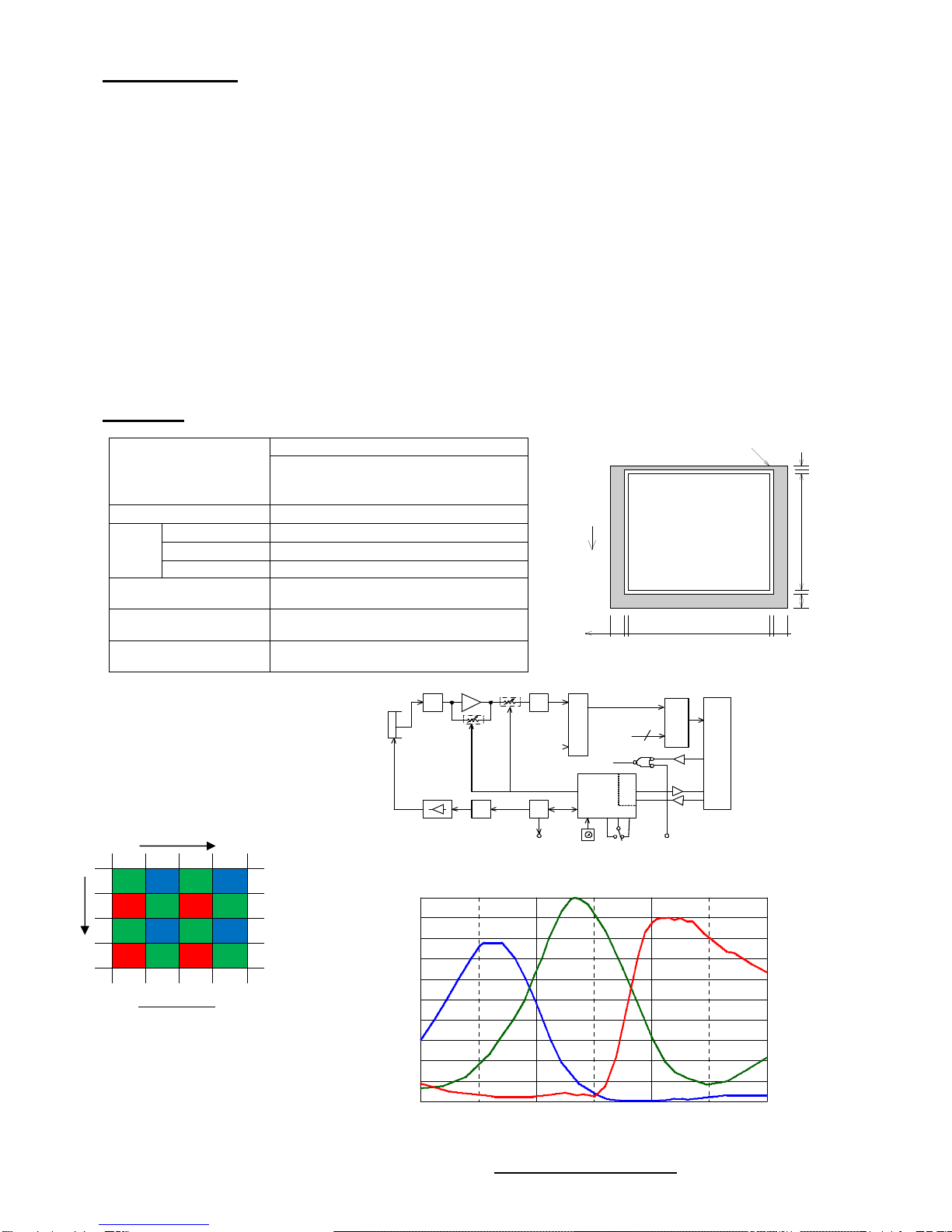
When the test pattern function is set to be ON, the imaging device
outputs not pictures but the test pattern as shown on the right.
As for this pattern, a numerical value of 4 is simply added in an
incremental manner for every horizontal pixel, and a saw-tooth profile is
shown in the range from the numerical value of 0 to 1023.
(Lower part of the right figure)
(Note) In the data, a numerical value of 1 is incrementally added for
every horizontal pixel in the range of 0 to 1023 for the case of 10
bit output, and in the range of 0 to 255 for the case of 8 bit
output.
(Note) The value does not start with 0 at the edge of the effective image area.
(Note) The output values of the test pattern are not affected by the values of the gain setting or offset setting of the
camera.
The default setting is OFF. This setting can be changed on the configuration menu (Operation Mode Setting Group 4) or
by way of rewriting the configuration register with serial communication commands.
(4-6) Monitoring function for internal temperature of camera
This camera is equipped with an internal temperature sensor to monitor the temperature inside the body. This function
makes it possible to use the camera in a safer way even in a harsh environment in terms of temperature, for example use
in the open air. With the use of serial communication commands, this function also works to control the forced air-cooling
fan of the camera and peripheral devices and others.
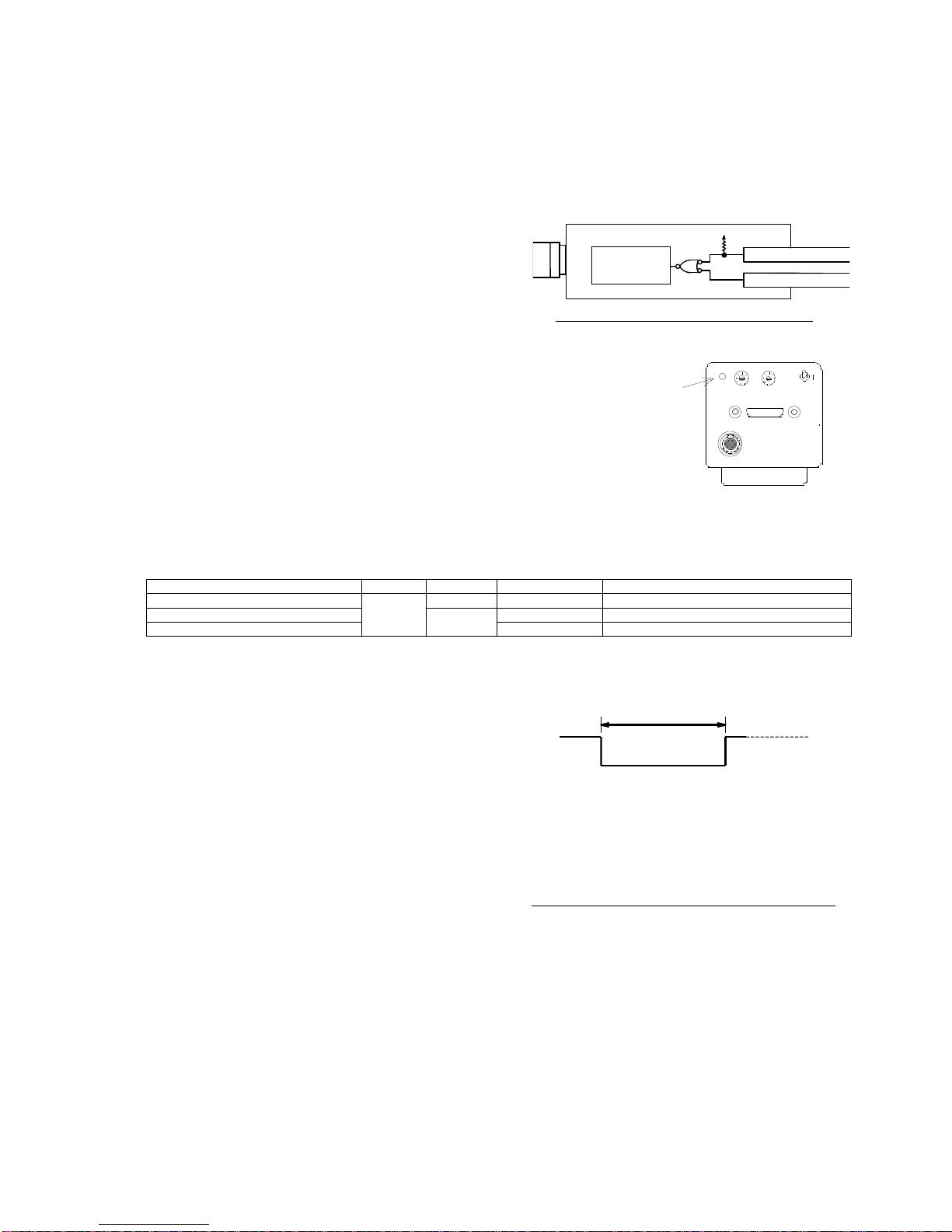
●How to monitor internal temperature of camera
The following two methods are available for monitoring the internal temperature of the camera:
●Turn on the MENU display and confirm it by the OSD over the image. (Temperature to be displayed in Celsius)
●Confirm it by temperature data to be returned in response to the RS-232C command (”RTMP” command).
(Numerical conversion required separately)
(Note) Carefully note that the temperature data obtained by this monitoring function is not for the ambient temperature but
the internal temperature of the camera. As a general rule, the internal temperature of the camera is higher than the
ambient temperature because of the heat generation associated with the consumed electric power inside the
camera.
Even when the temperature monitored by this function exceeds the value of the “Operation ambient temperature”
shown in the specifications of the camera, no operational trouble will be caused as long as the ambient
temperature is equal to the one of the specifications or lower, and sufficient countermeasures against temperature
are taken.
●Detection performance for temperature data
Temperature resolution : 0.5°
Update interval of data : 0.4 sec.
Temperature detection accuracy: ±2°C (-40°C to +85° C), +3 to -2°C (55°C to 125°C)
Effective data range : -55°C to 125°C (as long as t he operation ambient temperature of the camera is
within the range defined by the specifications.)
●Temperature data by RS-232C communication
The temperature data to be returned in response to the “RTMP” command of RS-232C is generated in the following
format:
[Data format]
The lower 10 bits out of the 16 bits of the returned data are valid.
XXXXXD9D8…D0 (invalid upper 6 bits/valid lower 10 bits as the data)
Db=B’D9D8…D0 in the binary system shows a signed integer value in two’s complement form.
However, the effective range of the temperature data is limited to the following due to the operational restriction of the
temperature sensor:
Effective range of temperature data: -110 (-55°C) to +250 (125°C)
(Note) The accuracy of the values of the temperature data is not guaranteed when the operation ambient temperature is
not within the range defined by the specifications.
[Conversion method from retuned data to temperature in Celsius]
The temperature in Celsius is computed as Tc from the following formula where Dt is the signed integer number converted
from the above described 10 bit binary value of “Db=B’D9D8…D0”:
Internal temperature of camera: Tc=Dt×0.5°C
Test pattern and horizontal profile
0
1023

N08A29;10/33
- 10 -
(Example 1) Where Td, the returned value of the temperature data, is “H’0032” in the hexadecimal system, it is
expressed in the binary system as follows:
Td=H’0032=B’0000.0000.0011.0010
∴Db=B’00.0011.0010 =+50 (Only upper 10 digits of Td are valid.)
Then, Tc is calculated from the following formula: Tc=+50×0.5°C=+25°C
(Example 2) Where Td, the returned value of the temperature data, is “H’03FA” in the hexadecimal system, it is
expressed in the binary system as follows:
Td=H’03F1=B’0000.0011.1111.1010
∴Db=B’11.1111.1010 (Only upper 10 digits of Td are valid.) →Dt=-6 (↓Refer to [Explanation])
Then, Tc is calculated from the following formula: Tc=Dt×0.5°C=-6×0.5°C=-3°C
[Explanation] Example of conversion algorithm from data in the complement number system to signed data
The following example shows how to convert 10 digit data in the complement number system into ordinary signed data:
(1) Whether the value is positive or negative is determined by checking the uppermost bit (MSB) out of the 10 digit
number. When the MSB is 0, “+” is added, and when it is “1”, “-“ is added to the number (absolute value) to be obtained
in accordance with the below described (2).
(2) The absolute value is obtained from a binary number expressed in the remaining 9 digits including the lowermost bit
(LSB) as follows:
Simply convert into an integer number if the MSB is 0 (”+” sign) in accordance with (1).
Reverse each of all the 9 digits and add 1 to the result if the MSB is 1 (“-“ sign) in accordance with (1).
(3) The signed number is obtained from (1) for the sign and (2) for the absolute value.
* In the case of the (Example 2) as above, its sign is “-“ because the MSB is 1 in accordance with (1). The absolute value
is “6” because of (invert(B'11111010)+ 1 = B'00000101 +1 = 5+1 =6) in accordance with (2). Therefore, this value (Dt) is
expressed as “-6” in the ordinary signed number system.
(4-7) Operation confirmation buzzer
This equipment is designed to sound the confirmation buzzer of “pip” when a stroke is applied to the UP/DOWN switch on
the rear panel, or at the time of other manipulation including the start-up after power application.
The factory default setting is ON. This setting can be changed to cancel the buzzer.
[Procedure for switching buzzer between ON/OFF]
●Start up in the Setting Group 3. (Set the mode switch to the position “C” while the power is turned off. Then apply the
power while the UP/DOWN switch is positioned to either side.)
●Change the mode switch to the position 2” after confirming that the orange LED is flashing.
●When an upward stroke is applied to the UP/DOWN switch, the buzzer is set to be ON. When a downward stroke is
applied, it is set to be OFF.
●Simply turn off the power after the setting is complete. (The setting is saved.)
(4-8) Camera ID saving function
The ID code and other information set by the user for each camera can be stored in the camera and read out wherever
necessary.
The saved identification data for each camera including installation location in the case of using more than one camera
(e.g., “CAMERA-RIGHT” and “CAMERA-LEFT”) allows the user to easily control and identify the camera (s).
The setting is executed through the serial communication. The settable maximum number of characters are 15, and
alphanumeric characters (both uppercase and lowercase characters) and some special symbols such as ”+” and “-”
excluding the control codes can be used.
(→Refer to the section of “Serial Communication Control” for the details.)

N08A29;11/33
- 11 -
5. Various Settings
(5-1) Operation mode
●CCD output system ······ SINGLE output
( output from single port)
●Electronic shutter operation mode
Shutter mode
No shutter/continuous/asynchronous
Shutter speed category
High speed/low speed/pulse width control
(See the right schematic diagram)
●Scanning system ········· Normal scan/partial scan
→Refer to the following page (Section 6) for the
specific setting method.
(!) This camera does not support the asynchronous
shutter mode for the low speed shutter operation.
Table 5-1. Description of electronic shutter operation modes
Shutter
mode
No shutter Electronic shutter is not used.
Exposure time of imaging device is equivalent to one frame duration.
Exposure is continuously performed for each frame.
Continuous shutter Repeats exposure regardless of external trigger input (Vinit).
Repetition pitch is per frame.
Asynchronous shutter Electronic shutter is released each time the external trigger is input (Vinit).
The permissible shortest repetition pitch is [exposure time + 1 frame duration].
Type
of
shutter
speed
Normal shutter
(High speed shutter)
Shutter, the exposure time of which is less than one frame, is used.
The shutter speed can be set as a preset shutter speed at 9 different levels both for the
continuous shutter/asynchronous shutter mode.
(!) As for the shutter speed of the conventional FC series cameras, 8 different levels for the
asynchronous shutter mode.
Low speed shutter
The shutter, the exposure time of which is two frames or over, is used.
(Only for continuous shutter mode) The shutter speed can be set as a preset shutter speed at 9
different levels.
(Note) This camera allows this setting only for the continuous shutter mode.
Pulse width control
In case of the asynchronous shutter setting only, the shutter, shutter speed of which
corresponds to the pulse width (during an effective level) of the external trigger input (Vinit) ,
is released.
Shutter speed can be set as nH (n = 1 or larger integer number) in H (horizontal synchronous
time) unit.
Table 5-2 Description of other operation modes
Scanning
system
Normal scan The read out for each frame is conducted by the all pixel readout scanning.
Partial scan The read out for each frame is conducted by the partial readout scanning.
The vertical width of the longitudinal picture area corresponds to 790 lines at the central portion of
the image pickup area.
[Terminology] Preset shutter············This refers to the shutter speed setting other than those specified by the pulse width
control. More specifically, the shutter speed is preliminarily set by the shutter switch
positions from “1” to “9” for the continuous shutter operation, or the shutter switch
positions from “1” to “9” (PWC (where pulse width operation mode
setting)=DISABLED) or from “1” to “8” (PWC (where pulse width operation mode
setting)=ENABLE) for the asynchronous shutter operation. The shutter speed is
defined in the Table 6-1.
[Terminology] Pulse width control·····This is the way of setting or controlling the shutter speed by the width of the Vinit
signal that is externally input in the asynchronous shutter mode. With this camera,
this is selected by setting as “PWC=ENABLED” in the asynchronous shutter mode
together with the shutter switch position of “9”.
(!) With the conventional products, the pulse width operation mode is always enabled when “9” is selected for the shutter
switch in the asynchrony shutter mode. Carefully note that this camera, however, will be in the preset shutter mode
when “PWC=DISABLED (prohibited)” is set, even if the shutter switch is positioned at “9”.
[Terminology] High speed shutter·····This means the shutter of which shutter speed is shorter than 1 frame duration(=1
vertical synchronous time). The shutter speed is set as a preset fixed length of the 9
different levels that are determined by the position of the shutter switch (continuous
shutter and asynchronous shutter).
[Terminology] Low speed shutter······This means the shutter of which shutter speed is longer than 1 frame duration. The
shutter speed is set as a preset fixed length of the 9 different levels that are
determined by the position of the shutter switch (continuous shutter).
(!) This camera does not support the functions of “low speed/asynchronous shutter”.
Electronic shutter
operation mode
No shutter
operation
Electronic shutter
operation
Shutter
switch = 0
Shutter switch = 1 to 9
Asynchronou
s shutter
low speed
shutter
High speed
shutter
Preset
shutter
Pulse width
control
Continuous shutter
High speed
shutter
Fig. 5-1 Electronic shutter operation modes

N08A29;12/33
- 12 -
(5-2) Setting of shutter speed
The shutter speed is determined mainly by the shutter switch position from “0” to “9”.
When a shutter speed is specified using a communication command, the communication command is prioritized.
The shutter speed to be displayed is the one that is corresponding to the currently selected shutter switch position. When
“7” is selected for the mode switch, the current shutter speed can be changed.
(Note) The change of the shutter speed is enabled only when the shutter switch is set to any positions other than “0”.
As long as the shutter switch is positioned at “0”, shutter speed cannot be changed even if “7” is selected for the
mode switch and the UP/DOWN switch is manipulated. (The shutter is always OFF where the shutter switch = “0”)
→Refer to the next section (Section 6) for the specific setting method.
(!) Since FS5100SCL is equipped with the independent shutter setting switch and mode setting switch, it does not require
the setting manipulation for the current shutter speed unlike the FC20 series products.
(5-3) Level setting
The level setting is mostly divided into the
following two groups:
●Gain setting
This is to set the gain (amplification ratio)
of the preamplifier between the CCD
imaging device inside the camera to A/D
converter.
●Offset setting
This is to set the offset of the preamplifier
between the CCD imaging device inside the
camera to A/D converter.
→Refer to the next section (Section 6) for
the specific setting method.
(Note) As for the offset setting, it is
recommended to use the factory
default setting except for a special
case.
(Note) Follow the procedure (gain setting →
offset setting) if fine tuning of the offset
value is required.
Fig. 5-2 Conceptual diagram of gain and offset levels
Signal level
1023
0
Time
Image signal
(Before setting adjustment)
Increase in GAIN
Increase in OFFSET
Signal level
1023
0
Time
Signal level
1023
0
Time
Output system
Left side of screen
Output system
Left side of screen
SINGLE
GAIN setting value
SINGLE
OFFSE
T setting value

N08A29;13/33
- 13 -
(5-4) MGC gain setting value
●Gain variable amplifier and integrated gain
The image signal output from CCD is amplified inside the
camera through the following variable gain amplifier and
then through the fixed gain amplifier before being input into
the A/D converter.
The left block chart shows this flow.
(Note) The gain value (dB) described here is the one based on the CCD output (0 dB) as the baseline.
●Correlation between MGC gain setting value and MGC gain
The MGC setting value of this equipment is controlled
by giving 24 to 224.
The correlation between this setting value and the
MGC gain (integrated gain including the gain of the
variable gain amplifier and that of the fixed gain
amplifier) is shown in the right graph.
(Note) When the CCD element receives excessive light
with a low gain value of the amplifier, the signals
of the nonlinear area of the CCD element and
the preamplifier are output at the high
brightness area due to the restriction of the
dynamic range of the CCD light receiving
element.
In this state, unnatural image (Note below) may
appear in the neighborhood of the saturating
signal area of the image due to the
characteristic of the nonlinear area. This
phenomenon, which is associated with the
saturation characteristic of the CCD element, is
not a failure arising from the camera.
To eliminate this phenomenon, reduce the
amount of light by stopping down the lens and
newly set a higher gain value. Then, the output
signal from the CCD element at the saturating
area will be appropriately saturated into a white
level for the output.
(Note) The above described unnatural image
represents the following states:
●Black and white look inverted at the saturating area.
●The outline of the saturating area is blurred.
●The saturating area slightly shifts upward or downward.
●The brightness value of the saturating area does not reach 1023.
(5-5) Program page setting
The FC series cameras incorporate nonvolatile memories
and various operation mode settings and level settings can
be stored in them.
The setting items are stored in the virtual pages (hereinafter
referred to as “program pages”) inside the camera.
This camera has 6 program pages of “A”, “B”, “C”, “D”, “E”
and “F” (right figure).
The camera starts operating according to the various
settings stored in the relevant page when the mode switch is
at any one of the positions from “A” to “F” at the time of
power-on.
The camera starts operating according to the settings stored
in the page “A” when the mode switch is at any position other
than those from “A” to “F” at the time of power-on.
1 to 16 dB
GAIN
3
dB (Fixed)
A/D
Preamplifier
V
ariable gain
amplifier
Fixed gain amplifier
CCD
Integrated gain
MGC setting
4 to 19
dB
Program page F
Program pages from B to E
Program page A
[Electronic shutter operation mode]
•Shutter system = Continuous/asynchronous
•Type of shutter speed = High speed/ low speed
•Electronic shutter table =
Correspondence
relation between
shutter switch and shutter
speed
[Other operation modes]
•Scanning system = Normal/partial -scan
[Level setting]
•
Gain setting value = (Saved as the internal value)
•Offset = (Saved as the internal value)
Fig. 5-3 Conceptual diagram of program page
MGC GAIN CODE
M GC GA IN (d B)
6
12
18
24
0
20 40 60 80 A0 C0 E0 (hex)
32 64 96 128 160 192 224(dec)

N08A29;14/33
- 14 -
=
Group 1
=
Menu-1
:
Display ON
LED
:
Blink in green
Mode switch : [1]
UP/DOWN switch : UP
Mode switch : [1]
UP/DOWN switch : UP
Mode switch : [1]
UP/DOWN switch : UP
Mode switch : [1]
UP/DOWN switch : UP
=
Group 2
=
Menu-2
:
Display ON
LED
:
Blink in green (quick)
=
Group C
=
Menu-3
:
Display ON
LED
:
Blink in orange
=
Group 1
=
Menu-1
:
Display OFF
LED
:
Blink in green
=
Group D
=
Menu-4
:
Display ON
LED
:
Blink in orange (quick)
=
Factory deafult
=
LED
:
Blink in red
Mode switch : [1]
UP/DOWN switch : UP
Mode switch : [1]
UP/DOWN switch : DOWN
MENU Nondisplay
Fig. 6-1 Flowchart of operation mode
6. How to Change Setting
(6-1) How to set shutter speed
The shutter speed is determined mainly by the setting positions of the shutter switch from “0” to “9”.
Table 6-1 Setting value of shutter speed
Position of shutter switch
High speed shutter
(continuous/asynchronous) Low speed shutter (continuous)
0 No shutter (continuous)
1/ 9 second 1/ 9.0 second
1 1/13000 second (1H) 1/4.5 second (2V)
2 1/ 4000 second ( 4H) 1/3.0 second (3V)
3 1/ 2000 second ( 9H) 1/2.3 second (4V)
4 1/1000 second (18H) 1/1.8 second (5V)
5 1/ 500 second (37H) 1/1.5 second (6V)
6 1/ 250 second (75H) 1/1.3 second (7V)
7 1/ 120 second (156H) 1/1.1 second (8V)
8 1/ 60 second (313H) 1/1.0 second (9V)
9 1/ 30 second (628H) 1/0.9 second (10V)
Pulse width control / asynchronous (!)
(Note) (H) and (V) in the table represent the horizontal time unit and the vertical time (frame duration) unit respectively.
(Note) ”No shutter” in the table means the continuous shutter mode with exposure time = 1 frame period.
(Note) The value of each shutter speed is the factory default value. The shutter speed of each position (excluding shutter
position = 0) is possible to change by the user in the operation mode [Group 1].
(!) As for this camera, it must be set to be “Pulse width control (PWC) = ENABLED” for implementing “Pulse width control
/asynchronous” shutter operation .
When it is set to be “Pulse width control (PWC) = DISABLED” (default), the selection can be made out of the 9 levels
not only for the continuous shutter operation but also for the asynchronous shutter operation.
(6-2) How to set operation mode
The setting items of the operation modes are divided into 4 groups of Group 1, Group 2, Group C and Group D as follows:
Group 1·············These are mainly used for setting the basic functions (shutter speed
change, gain change etc.). Set the mode switch to the position
corresponding to the item to be changed and then manipulate
UP/DOWN switch to change the setting.
Group 2·············These are mainly used for setting the auxiliary function (gain
correction setting). Set the mode switch to the position
corresponding to the item to be changed and then manipulate
UP/DOWN switch to change the
setting.
Group C and D····· These are mainly used for setting the
configuration items (Terminology below).
Set the mode switch to the position
corresponding to the item to be changed and then
manipulate UP/DOWN switch to change the setting.
(Note) When any setting item is changed, it must be saved in one of
the program pages from “A” to “F” before turning off the power to store the data in the memory of the camera.
Carefully note that the new setting is not automatically saved and that the prior setting will be effective at the next
time of power-on if the power is turned off before storing it. The configuration items, however, are automatically
saved whenever they are changed.
[Terminology] Configuration items ····They are the common setting items that are independent of the program pages.
These items are automatically saved in the internal EEPROM at the same time as
they are changed by manipulating the switches on the rear panel.

N08A29;15/33
- 15 -
Table 6-2 Start-up condition for each setting Group
Start-up condition (at time of power-on) The groups of Operation
Mode Setting Operation state of camera at
start-up
Position of mode switch UP/DOWN switch
Arbitrary position
from 0 to F Neutral position (no switch
manipulation) Group 1 By normal automatic loading
(→Table 6-8)
Table 6-3 Set contents for Operation Mode Setting [Group 1]
Position of
mode switch
Item to be changed UP/DOWN switch
UP position DOWN position
0 Change of gain Increase in gain Decrease in gain
1 Menu display (MENU) <* C> Group2 MENU OFF
2 Selection of gain preset 1 or 2 Preset 2 (
±
0db)
Preset 1 (-3db)
3 Selection of gain preset 3 or 4
Preset 4 (+12db)
Preset 3 (+6db)
4 (Not used)
5 Shutter – continuous/asynchronous (S.FORM ) Continuous
(NORMAL) Asynchronous
(ASYNC)
6 Shutter – high speed/low speed (S.TIME) High speed (HIGH) Low speed (LOW)
7 Change of shutter speed (S.TIME) Shorter Longer
8 Digital offset (OFFSET) Increase in offset Decrease in offset
9 Switch between normal scan/partial scan (SCAN) All pixels (NORMAL) Partial (PARTIAL)
A to F Program pages from A to F Save Load
(Note ) Decibel value in “Selection of gain preset” is a relative value based on Preset 1.
(Note) The shutter speed can be changed only when the shutter switch is currently set at any other positions than “0”.
When the shutter switch is positioned at “0”, the shutter speed cannot be changed even if the mode switch is set to
the position “7” and the UP/DOWN switch is manipulated. (The shutter is always OFF where shutter switch = “0”.)
Table 6-4 Set contents for Operation Mode Setting [Group 2]
Position of
mode switch
Item to be changed UP/DOWN switch
UP position DOWN position
1 Menu display (MENU) <* C> Group C MENU OFF
2 Gain correction (GAIN B) +Gain correction -Gain correction
3 OFFSET correction (OFFSET B) +Offset correction -Offset correction
4 Enabled/disabled for pulse width control (PWC) (!) ENABLED DISABLED
A to F Program pages from A to F Save Load
(!) When the setting of “ Enabled/disabled for pulse width control” is not set to be “ENABLED”, the pulse width control is
not effective even if the shutter switch is set to the position “9” for the asynchronous shutter operation. In this case, the
preset shutter in asynchronous shutter mode is effective.
Table 6-5 Set contents for Operation Mode Setting [Group C]
Position of
mode switch
Item to be changed UP/DOWN switch
UP position DOWN position
1 Menu display (MENU) <* C> Group D MENU OFF
2 Operation confirmation buzzer (BZ) <* C> ON OFF
3 Serial communication baud rate (BAUDP) <* C> 19200 bps 9600 bps
4 to 5 (Not used) (-) - -
6 Polarity setting for Vinit2 (Vinit2) <* C> Positive logic
(INVERTED)
Negative logic
(NORMAL)
7 Continuous shutter strobe signal (STRB-C) <* C> ON OFF
Table 6-6 Set contents for Operation Mode Setting [Group 4]
Position of
mode switch
Item to be changed UP/DOWN switch
UP position DOWN position
1 Menu display (MENU) <* C> Factory default MENU OFF
2 Test pattern (PATTERN) <* C> ON OFF
3 Output bit (BIT) <* C> 10bit 8bit
4 to 6 <Not used> (-) - -
7 Vsub voltage (VSUB) <* C> Increase in voltage Decrease in voltage
•(Note) Vsub voltage is appropriately adjusted before shipment, and therefore the setting value should
not be changed unless there is some particular reason.
If the value is changed by mistake, it can be reset to the factory default by executing “(6-9) Read out of factory
default”.
[Explanation] Vsub voltage
Vsub voltage is the bias voltage (substrate voltage) that serves to control the blooming effect (resulting in blur or running
image at a saturating area) that arises from excessive light getting into CCD.
If a high Vsub voltage is set, the blooming effect can be reduced, although an excessively high voltage leads to a
narrower operation range of CCD because it is associated with a decrease in the saturating voltage of the CCD output.
It is appropriately set before shipment because the optimum Vsub voltage varies by CCD.

N08A29;16/33
- 16 -
Table 6-7 Set contents for Operation Mode Setting [Factory default]
Position of mode
switch Item to be changed UP/DOWN switch
UP position DOWN position
0 Initialization Initialization
Initialization
1 Menu display (MENU) <* C> Group 1 Menu OFF
2 Read out default value Read Read
* Notes in common with all setting groups
(Note) The standard factory mode (default) is underlined.
(Note) The items marked with <* C> in the table (configuration items) are automatically stored in EEPROM whenever they
are changed.
(Note) The new settings of the other items than the configuration items are lost at the time of power-off unless they are
manually saved in the program pages after changing them.
(6-4) Setting of program page
The setting operations for the program pages are roughly divided into 2 groups: save (writing the current setting into the
program page) and load (reading out the setting that was previously saved in the program page as the current setting).
More specifically, “save” means overwriting the new setting that was changed from the current one onto one of the
program pages after turning on the power while “load” means the opposite operation that is reading out the setting saved
one of the program pages as the current setting.
The camera operates on information of
the
current setting in RAM.
Program page F
Program pages from B to E
Program page A
[Electronic shutter operation mode]
•Shutter system = Continuous/asynchronous
•Type of shutter speed = High speed/ low speed
•Electronic shutter table =
Correspondence
relation between
shutter switch and shutter
speed
•Pulse width control = Enabled/Disabled
[Other operation modes]
•Scanning system = Normal scan/Partial scan
[Level setting]
•Gain setting value = (Saved as the internal
value)
•Offset = (Saved as the internal value)
[Electronic shutter operation mode]
•Shutter mode = Continuous/asynchronous
•Type of Shutter speed
= High speed/ low speed
•Electronic shutter table =
Correspondence
relation between shutter switch and shutter
speed
• Pulse width control = Enabled/Disabled
[Other operation modes]
•Scanning system = Normal scan/Partial scan
[Level setting]
•Gain setting value = (Saved as the internal
value)
•Offset = (Saved as the internal value)
Current settings
Save
Load
Effective even after power-off
Lost at power-off
Fig. 6-2 Conceptual diagram of saving and loading operations
[Explanation] Correlation between current setting and program page
The setting information saved in the program page is automatically read out to RAM (volatile memory) when the
camera is turned on, and that determines the operation of the camera as the current setting.
When the setting of a mode is changed, the older one is overwritten, and the new setting is temporarily effective as
the operation setting for the camera until the power is turned off. The new setting in the program page on RAM,
however, is lost when the power is turned off, and the old setting before power-on will be effective for the operation of
the camera.
Accordingly, it is absolutely necessary to write the new setting in one of the program pages from “A” to “F” to save it.
The setting saved in the program page can be read out for use by the loading operation (including automatic load at
power-on) as described later.
●Automatic load at power-on
When the power is turned on, the camera automatically loads the setting stored in one of the program page from “A” to
“F”, which determines the operation of the camera.
The program page of which setting is automatically loaded is determined by the position of the mode switch at the time
of power-on.
(Note) Note that the setting of the program page “A” is automatically loaded when the switch is at any position other than
“B” to “F”.
●Manual load/save
Manual load/save of the setting from/to the program page can be enabled when setting the mode switch to one of the
positions from “A” to “F” and manipulate the UP/DOWN switch after the power is turned on.
(Note) This saving operation must be performed to keep the new setting effective for later use after changing it.
Table 6-8 Automatically loaded
program page Table 6-9 Setting operation for program page (manual operation)
Position of
mode switch
Automatically loaded
program page Position of
mode switch
Item to be
changed UP/DOWN switch
UP position DOWN position
0 to A Program page A A Program page A
Save Load
B Program page B B Program page B
C Program page C C Program page C
D Program page D D Program page D
E Program page E E Program page E
F Program page F F Program page F

N08A29;17/33
- 17 -
FS5100SPL
[VX.XX]
Menu display of Setting Group 1
MENU1
MENU : *ON
GAIN : 120 / SET2
OFFSET : 160
S.TIME : OFF (66.67)ms
S.FORM : ASYNC / HIGH
SCAN : NORMAL
Tc= 30.0 deg
MS=1
SS=0
MF=0008.0001
(6-5) Description of menu display by OSD (On Screen Display)
This camera is equipped with the OSD function of superimposing a
character information on the output digital image signal. Using this
function, the current setting status of the camera can be displayed over
the image of the capture board in menu-driven form.
(Note) This camera is basically designed so that all settings can be done
without this menu display by OSD just like the conventional
cameras of FC series. However the menu display allows the user
to quickly understand the current settings at a glance.
Furthermore, if the contents of the menu display are captured and
saved before collecting data using the camera, they serve as
useful information to be referred when comparing data or setting
additionally introduced cameras.
[Requirement for menu display]
The menu display requires a system that is capable of updating the captured image constantly responding to the timing of
FDV/LDV to be output from the camera on the side of the user‘s capture board.
When the asynchronous shutter mode is set for the camera, the repetitive asynchronous shutter operations are
automatically made at certain intervals to automatically refresh the image so that the menu display is updated. During this
process, the externally input trigger signals are ignored.
The display area of OSD is located on the upper left on the entire area of the captured image, and therefore this system
must be additionally capable of displaying this menu on the screen.
[ON/OFF operation of menu display]
If the OSD menu display does not appear on the capture image, perform the following procedure to display it:
Turn on the power in the normal manner →Set the mode switch to “1” →Apply an upward stroke to the UP/DOWN switch
To disable the output of the menu display, perform the same procedure except for applying a downward stroke to the
switch.
(Note) Since the ON/OFF setting of the menu display is a configuration item, it is automatically saved in the internal
EEPROM.
(Note) If the menu display is set to be ON in the asynchronous shutter mode, the repetitive trigger (cyclic trigger) that is
generated inside the camera is automatically input. Make sure to set the menu display OFF when the camera is
used in the normal state (online state).
(Note) Note that the difference between the pulse width generated by the camera with the menu display turned on and
that provided by the user unit results in the difference in the brightness of image between those when the
asynchronous shutter operation in the pulse width control mode is set (S.FORM=ASYNC/HIGH,
PWC=ENABLED).
[Description of display content]
MENU 1, A, C or D: Current setting is displayed.
The following is displayed:
”1”: Set content of Setting Group 1
”A”: Set content of Setting Group 2
”C”: Set content of Setting Group C
”D”: Set content of Setting Group D
MENU: Current menu status is displayed.
When the menu is being displayed, “ON” is kept displayed.
When “(CYCLIC)” is displayed on the right, the camera is cyclically
outputting the asynchronous shutter image using the internal
trigger to refresh the image.
When the asynchronous shutter mode is set and the menu is set to ON, the cyclic trigger input is
automatically selected. When the menu is set to OFF, the cyclic trigger input is automatically cancelled and
external trigger is ready to be received.
GAIN: The left number is the gain setting value expressed in the decimal system. (Range: 16 to 192).
When gain set value coincides with gain preset value (four levels of preset value), “SET” followed by
corresponding gain preset No. is displayed on the right side.
OFFSET: The set value of the digital signal offset is displayed in the decimal system. (Range: 32 to 224)
S.TIME: The current shutter speed is displayed. The left number is H number (horizontal synchronous time unit, in
the case of high speed shutter – range: 1 to 2073 <normal scan> or range: 1 to 1039 <partial scan> in
decimal system) or V number (vertical synchronous time unit, in the case of low speed shutter – range: 1 to
255 in decimal system). The right number in parentheses shows the actual time.
The actual time is displayed after being converted in accordance with the settings of the scan mode (all
pixels/partial) and shutter mode (HIGH/LOW).
(Note) When the pulse width control mode is set for the asynchronous shutter operation or when a shutter setting value is
out of the predetermined range in the partial scan mode, the actual time is displayed as “--.-”.
OSD display area
Entire area of captured image
Display position by OSD

N08A29;18/33
- 18 -
S.FORM: The current shutter operation mode is displayed. The left is either continuous (NORMAL) or asynchronous
(ASYNC), and the right is either high speed (HIGH) or low speed (LOW).
SCAN: The current scanning system is displayed. It is either all pixel readout scan (NORMAL) or partial readout
scan (PARTIAL). (→See “Priority relationship among scan mode setting items” described in another
section)
PWC: Whether the position “9” of the shutter switch for the
asynchronous shutter operation is used (ENABLED) or not
used (DISABLED) is selected.
BZ: This is to switch between (ON) and (OFF) for the confirmation
sound to be activated when switch manipulation is made.
BAUD: The baud rate used for RS-232C communication is displayed.
Vinit2: The polarity of the trigger signal via CC1 of Camera Link is set.
The factory default is negative logic (NORMAL). When
(INVERTED) is selected, positive logic input is used.
STRB-C: ON/OFF is set for the strobe signal (STRB) output for the
continuous shutter operation. When (ON) is selected, the
strobe signal is output even in the continuous shutter mode.
(Note) The strobe signal is always output in the asynchronous shutter mode
regardless of this setting.
PATTERN: This is to switch between (ON) and (OFF) for the test pattern
output.
bit: This is to switch between (8 bits) and (10 bits) for the bit of the
image output.
FORM.: SINGLE (1ch output) is displayed as the CCD output system.
VSUB: The setting value of Vsub voltage (substrate voltage of CCD
element) is displayed.
Since the value is optimally set before shipment, the user is
not required to change it as a general rule.
* The following items are for display only; they cannot be directly changed
on the menu. These are automatically updated when a corresponding
change is made using the switches:
MS= The current position of the mode switch is displayed.
SS= The current position of the shutter setting switch (EXP.) is
displayed.
MF= The information (16 bits x 2 sets) of the internal mode flags
of the camera (internal flags to determine operation) is
displayed in the hexadecimal system. The details of the
internal flags are described later.
Tc= The current internal temperature of the camera is displayed in Celsius. The temperature data are refreshed
every 0.4 seconds.
F
S
5100
S
P
L
[V.X.XX]
Menu display of Setting Group 2
MENU2
MENU : ON
PWC : DISABLED
- : (Reserved)
MS=A
SS=7
MF=0008.0000
F
S
5100
S
P
L
[V.X.XX]
Menu display of Se
tting Group C
MENU
3
MENU
:
ON
BZ : ON
BAUD : 9600bps
- : (Reserved)
- : (Reserved)
Vinit 2 : NORMAL
STRB-C : OFF
MS=
C
SS=7
MF=0008.0000
F
S
5100
S
P
L
[V.X.XX]
Menu display of
Setting Group D
MENU
4
MENU : ON
PATTERN : OFF
bit : 8bit
FORM. : SINGLE
- : (Reserved)
- : (Reserved)
VSUB
: 204=H'CC
MS=
C
SS=7
MF=0008.0000
MS=1 SS=7
MS=1 SS=7
ID: CAMERA-1
FS5100SPL
ID not specified
ID specified

N08A29;19/33
- 19 -
[ID information display]
The ID code and other information set by the user for each camera can be saved in the camera (with the use of the serial
communication).
The settable maximum number of characters are 15, and alphanumeric characters (both upper and lower cases) and
some special symbols such as”+” and “-” excluding the control codes are used.
(→Refer to the section of “Serial Communication Control” for the details.)
The ID code set by the user is displayed on the lower left of the “Menu Display of Setting Group 1” by the OSD function;
this allows the user to confirm the setting content (ID: onward).
(If the ID code is not set, the camera model name is displayed instead.)
The bottommost and right figure on the previous page shows an example where “CAMERA-1” is set as the ID information.
[Change of setting]
Perform the procedure described in another section: “(6-3) How to set operation mode” when changing the current setting
while referring to the information displayed by the OSD function.
When the position of the mode switch is changed, a flashing “ * ” mark appears on the left of the numeric value or the
parameter of the item corresponding to the switch position to indicate that the setting can be changed using the
UP/DOWN switch.
When a stroke is applied to the UP/DOWN switch, the value of gain or others increases or decreases by 1. When a stroke
is applied and kept for about 2 seconds, the number continuously increases or decreases at fast speed after the response
sound of “pip-pip”.
[Save of setting after change]
The settings changed on the menu are divided into 2 groups; one is for those that are automatically saved in the
nonvolatile ROM area whenever a change is made (configuration items) and the other is for those that are saved in the
program pages only when manually stored (See the following table).
Automatic save and manual save Item Remark
Items automatically saved when changed on menu
“MENU” Reflected in (CR)
“BZ” Reflected in (CR)
“BAUD” Reflected in (CR)
“Vinit2” Reflected in (CR)
“STRB-C” Reflected in (CR)
“PATTERN” Reflected in (CR)
“VSUB” Saved as numerical value
Items requiring manual save into program pages after
changed on menu
“GAIN” Saved as numerical value
“OFFSET” Saved as numerical value
“S.TIME” Saved as numerical value
“S.FORM” Reflected in (FR)
“SCAN” Reflected in (FR)
“PWC” Reflected in (FR)
(Note) The value of “VSUB” is stored in an area independent of the program pages.
(6-6) Internal flag register (FR) and configuration register (CR)
The camera internally has RAM areas for the flag register (FR) (2 bytes) and the configuration register (CR) (2 bytes).
If the user checks the contents of these registers, he or she can get the information on the current operational status. In
addition, it is possible to change more than one operation mode at a time by way of rewriting the contents of the registers.
In this section, the functions of the flag register and the configuration resister are described.
●Flag register (FR) and configuration register (CF)
Both FR and CR are 2 bite (16 bit) memory areas in RAM. When the camera is turned on, the data stored in the
internal EEPROM (nonvolatile storage) are read out and copied into these areas. The current operation mode of the
camera is determined by the data in FR and CR.
Each set of FR data is saved in each of the program pages (Ato F), and the data are copied to the flag register by the
automatic loading at the time of power-on or manual loading onto one of the program pages to determine the operation
of the camera. On the contrary, the memory area for CR in EEPROM is only one and the data are read out separate
from the program pages to determine the operation mode.
●The data of those registers can be changed by manipulating the switches on the rear panel of the camera (regardless
of ON/OFF state on the menu display) or using serial communication commands.
●When the menu display is set to “ON”, the contents of (FR) and (CR) are displayed as 8 numbers like “MF=0000.0000”
to show the current states of the registers. The numbers are expressed in the hexadecimal system. The first (upper) 2
bytes show the setting data of the configuration register (CR) and the bottom (lower) 2 bytes show the setting data of
the flag register (FR).

N08A29;20/33
- 20 -
[Description of CR data]
Bit Abbrev.
Content Logic Remark
0 MNI Disabled display of menu screen 1: Disabled (OFF)
1 BZI Disabled buzzer output 1: Disabled (OFF)
2 TPEN ON/OFF selection for test pattern 1: Test pattern ON
3 DFRM Selection of output data format 1: 8bit format 0: 10bit format
4 CLKP (Not used)
5 TWEN (Not used)
6 STRBC Enabled STRB signal output for continuous
shutter 1: Enabled
7 CC1P Selection of trigger signal (Vinit2) polarity
via CC1 1: Positive polarity
8 - (Not used)
*1
9 BAUD 9600bps/19200bps selection for serial
communication rate 1=19200bps
10 - (Not used)
11 - (Not used)
12 - (Not used)
13 - (Not used)
14 CCDO (Not used)
15 DEFR Request for reading out default value at
next start-up 1: Request *1
(Note) All the items of the CR data are “0” as factory default, except that CR (3) = ”1”.
*1: No change can be executed by a communication command.
[Description of FR data]
Bit
Abbrev.
Content Logic Remark
0
ASYE
Selection of continuous/asynchronous shutter
1: Asynchronous (ASYNC)
1
PWCE
Selection of enabled/disabled for pulse width
control 1: Enabled pulse width control
2
LEXE Selection of high speed/low speed shutter 1: Low speed shutter
3
PSCE
Selection of normal scan/partial scan 1: Partial scan
4
- (Not used)
5
- (Not used)
6
- (Not used)
7
- (Not used)
8
ESP(0)
Externally designated shutter speed position H'0 to H'9 or H'F
Where ESPE=1, externally
designated number from 0
to 9 (designated position) is
reflected.
In case of H'F, external
shutter speed in H unit is
selected.
9
ESP(1)
10
ESP(2)
11
ESP(3)
12
ESPE
Effectiveness of externally designated shutter
speed 1: Effective
13
- (Not used)
14
- (Not used)
15
AGCE
(Not used)
(Note) All the items of the FR data are “0” as factory default.
(Example)If “MF=H’0008.0003” is displayed on the menu screen, the camera is in the following state (converting the
numbers to ones in binary system):
H’00=B’00000000, H’08=B’00001000 and H’03=00000011 are substituted to the above numbers.
CR=B’0000000000001000, FR=B’0000000000000011
……… CR(3)=FR(1)=FR(0)=1, All other bits = 0
(Where CR(n) and FR(m) represent the nth bit of CR and mth bit of FR respectively)
Based on 1 or 0 of these bits and the information in the above table, the user can know that the camera is in the
state of “8bit format”, “ASYNC” and “Enabled pulse width control”.
[Explanation]
The setting values (1 or 0 of respective bits) of (CR) and (FR) vary according to the change to be made using the switches
on the rear panel of the camera. The operation modes that cannot be changed by the RS-232C commands can be
changed by altering the bits of (CR) and (FR).
(Example 1) When a change is made from the continuous shutter mode →asynchronous shutter mode,
“MF=0000.0000” is replaced by “MF=0000.0001” (ASYE bit = 1).
(Example 2) When CR (0) is changed from 0 →1 using a serial communication command, “ON” on the menu display is
replaced by “OFF” (MIND=1).
Table of contents
Other Takenaka System Color Camera manuals