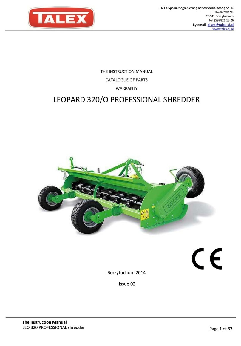
Talex MULCHER ECO User manual

Z-908 FLM 100;135;150;150H;180;200;220;180 H;200H;220H
MOWER
MULCHER ECO
Models: 100; 135; 150; 150H; 180; 180H; 200;
200H; 220; 220H

Z-908 EKO SHREDDER
Page 2
IT IS STRICTLY
FORBIDDEN TO USE THE
SHREDDER WHILE NON-
OPERATORS ARE WITHIN
LESS THAN 50 M FROM
THE DEVICE

Z-908 EKO SHREDDER
Page 3
TABLE OF CONTENTS
Index
1. DEVICE IDENTIFICATION DATA:.......................................................Błąd! Nie zdefiniowano zakładki.
2. INTRODUCTORY REMARKS..............................................................Błąd! Nie zdefiniowano zakładki.
2.1. Read the manual carefully............................................................Błąd! Nie zdefiniowano zakładki.
2.2. Machine purpose..........................................................................Błąd! Nie zdefiniowano zakładki.
2.3. Important provisions concerning purchase procedure .................Błąd! Nie zdefiniowano zakładki.
2.4. Warranty.......................................................................................Błąd! Nie zdefiniowano zakładki.
3. GENERAL PRECAUTIONS AND WORK SAFETY ...................................................................................5
3.1. General precautions .....................................................................Błąd! Nie zdefiniowano zakładki.
3.2. Transportation.....................................................................................................................................5
3.3. Working elements of the machine................................................Błąd! Nie zdefiniowano zakładki.
3.4. Machine attached to the three-point hitch..........................................................................................6
3.5. Machine disconnected from the tractor ........................................Błąd! Nie zdefiniowano zakładki.
3.6. Using the jointed telescopic shaft.................................................Błąd! Nie zdefiniowano zakładki.
3.7. Handling........................................................................................Błąd! Nie zdefiniowano zakładki.
3.8. Equipment and spare parts ..........................................................Błąd! Nie zdefiniowano zakładki.
3.9. Technical specification .................................................................Błąd! Nie zdefiniowano zakładki.
3.10. Construction and mode of operation............................................Błąd! Nie zdefiniowano zakładki.
4. Operation..............................................................................................Błąd! Nie zdefiniowano zakładki.
4.1. Attaching the shredder to a tractor...............................................Błąd! Nie zdefiniowano zakładki.
4.2. Starting work.................................................................................Błąd! Nie zdefiniowano zakładki.
5. RECOMMENDED HANDLING ;...........................................................Błąd! Nie zdefiniowano zakładki.
5.1. Lubrication....................................................................................Błąd! Nie zdefiniowano zakładki.
5.2. Belt tightness................................................................................Błąd! Nie zdefiniowano zakładki.
6. SERVICING, STORAGE, DISPOSAL......................................................................................................13
6.1. Storage.........................................................................................Błąd! Nie zdefiniowano zakładki.
6.2. Disassembly and disposal............................................................Błąd! Nie zdefiniowano zakładki.
7. PARTS CATALOG ...................................................................................................................................13

Z-908 EKO SHREDDER
Page 4
1. DEVICE IDENTIFICATION DATA
Producer name, production year, and serial number of the machine are provided in the nameplate located on
the body of the shredder. The nameplate incorporates the name and address of the producer, production
year, machine symbol, serial number, and the KJ label.
The dealer or the producer shall provide all information concerning the machine and the clarification of the
data included in this manual.
Address date of the producer:
2. INTRODUCTORY REMARKS
If this symbol is visible next to any point of this manual, read the paragraph carefully, follow the
instructions provided therein, and inform other operators of the machine of the said type about
the possible danger!
2.1. Read the manual carefully
This manual is an integral part of the machine. Before proceeding to the execution of any works
involving the utilization of the shredder, familiarize yourself with the content of this document.
The manual incorporates info concerning proper usage, operation, and maintenance of the device in
question, as well as presents the operational characteristics, requirements allowing for safe and professional
usage of the shredder, and ensures the performance and longevity maximization. Moreover, it also
comprises of guidelines on replacement of spare parts. Careful lecture of this publication will make it
possible for the operator to avoid accidents, keep the warranty valid, as well as to maintain the shredder in
an impeccable condition, making it ready to use at all times.
2.2. Machine purpose
The machine has been designed for typical agricultural use that is –for mowing and fragmenting relatively
small flora (shrubs, stalks of plants, etc.).
Device is fully compatible with class II tractor.
Using the shredder for any other purpose shall be understood as improper utilization, discharging the
producer from the liability for all the damages caused by such exploitation.
Shredder can be taken advantage of only by properly trained individuals who have familiarized
themselves with the user’s manual and have necessary authorization to drive a tractor.
Device in question should be professionally used, operated, and maintained (exploitation of the
machine by unauthorized personnel such as children or teenagers may result in posing threat to their
health and life. It may also lead to damaging the device).
Always follow safety precautions provided in this publication, general safety measures, work safety
principles, and traffic regulations.
Follow safety precautions and work safety principles while performing machine maintenance or
operation-related undertakings.
Unauthorized modifications of the device shall result in discharging the producer from the liability for
all the damages caused by such adjustments.
2.3. Important provisions concerning the purchase procedure
This publication shall be presented to the purchaser together with the device. The Selling Party shall fill in
the “Agricultural machine and user’s manual collection protocol”. Before the acceptance of the device, check
its completeness basing on the Shipping Specification and examine whether or not the Selling Party had
properly filled in the warranty card, complaint coupons, and the title page of this manual.

Z-908 EKO SHREDDER
Page 5
2.4. Warranty
Warranty terms are provided in the warranty form. The careful lecture of this document is one of the
obligations of the operator. The failure to comply with the regulations on proper exploitation of the device will
lead to the decrease in its performance, increase in the malfunction risk, and the fact of the warranty being
deemed null and void. The warranty will be specifically cancelled in the following cases:
1. Identifying mechanical damages caused by disregarding the indications of the manual on proper
operation, especially –by mowing while on the reverse gear.
2. Fixing the device by servicing companies other than the Selling Party, Producer, or a company
suggested by the said parties;
3. Using unoriginal parts while repairing the shredder;
4. Modifying the construction of the device.
3. GENERAL PRECAUTIONS AND WORK SAFETY
The majority of accidents occurring while using, operating, or transporting the device results from the failure
of the operator to comply with basic safety precautions. It is of significant importance for the user to make
use of the recommendations provided below and follow them as strictly as possible:
3.1. General precautions
1. FOLLOW the recommendations of this publication, as well as general work safety principles!
2. OBSERVE safety indications and symbols located on the device. They have been placed there for
user’s safety!
3. IT IS FORBIDDEN to use the machine without the required covers attached. If they have been
damaged, replace them using original components.
4. SHREDDER SHOULD BE USED after reaching the nominal PTO (power take-off) rotational speed of
the tractor. For "URSUS" C-360, C-385m tractors, as well as the ones with a bigger engine, the said
speed is equal to 540 RPM. Moreover, the rotational velocity of 600 RPM should not be exceeded.
5. UNDER NO CIRCUMSTANCES should the machine be inspected or repaired while some parts are still
moving. It is highly recommended to wait for them to stop before attempting to inspect the device.
Avoid wearing clothes that may be easily torn apart by the moving components of the shredder.
6. UNDER NO CIRCUMSTANCES should the operator leave the working machine unattended.
7. Make sure that there are no unauthorized individuals or animals in a close proximity to the device
before its use, as well as during its exploitation. It is strictly forbidden to use the shredder while
non-operators are within less than 50 m from the device!
8. IT IS FORBIDDEN to climb on the machine.
9. FIELDS OR MEADOWS should be properly prepared for the use of the shredder –all the bigger rocks
and hard objects should be removed.
10. SHREDDER must not be used while reversing.
11. TRACTOR used should incorporate driver’s cabin.
12. IT IS STRICTLY FORBIDDEN to stand between the tractor and the machine until the shredder is
secured against detaching involuntarily by using the handbrake or locating chock under its wheels.
13. POSITION of the hydraulic lift lever should be changed only by the operator sitting in the driver’s cabin
of the tractor.
14. CHANGING the position of the lever from the outside of the tractor is not allowed.
15. IT IS NOT RECOMMENDED lifting the machine by means of the hydraulic lift of the tractor when its
engine is on and the working shaft is still rotating.
16. USING the shredder on slopes up to 30ois safe.
3.2. Transportation
Before setting the shredder in the transporting position, make sure that the PTO of the tractor is on and
all moveable parts are stopped.
BE EXCEPTIONALLY CAREFUL while transporting the machine along public roads; follow traffic
regulations. Moreover, for the transportation period, attach a signaling device and a triangular warning
plate to the device.

Z-908 EKO SHREDDER
Page 6
ADJUST the movement speed to the current road conditions. Do not drive too fast!
NOTE –while turning, the machine may lean backwards or to the sides.
3.3. Working elements of the machine
Before using the shredder, check if the blades are properly attached.
Blades that are worn out or damaged should be immediately replaced with new and original spare parts.
3.4. Machine attached to the three-point hitch
Before attaching the machine to or removing it from the three-point hitch of the tractor, set the hydraulic lift
lever of the tractor in the position in which the involuntary lifting or lowering the device is impossible.
Suspension categories of the tractor and the machine must be in line. While the shredder is in the
transporting position, check the stability of the tractor on the sides of the machine connector.
While transporting the device in the lifted position, the hydraulic lift lever must be always secured
against uncontrolled position change.
3.5. Machine disconnected from the tractor
Set the machine on a stable surface.
3.6. Using the jointed telescopic shaft
Use shafts recommended in this manual only.
All the protective covers of the jointed telescopic shaft must be in a proper condition. If they are
damaged, there is the need to replace them immediately.
Always attach and remove the shaft when the PTO and engine are off and the key is turned off!
Both halves of the jointed telescopic shaft should commeasure with one another in both transporting
and working positions!
Shaft cover should be protected by means of a chain to prevent its rotating together with the shaft!
Before turning the PTO on, check if the direction of rotation and the rotational speed of the PTO are
equal to the ones of the jointed telescopic shaft.
Ensure that there are no unauthorized individuals in a close proximity to the machine before turning the
shaft on.
Turn the shaft off if it is not to be used for a longer period of time.
After turning the said component off, wait for the inertial rotations to stop and only after that allow other
individuals to approach the shredder.
When the jointed telescopic shaft is turned off, attach protective covers to it and locate it in the
designated storage area.
In the case of the occurrence of any damages, they must be fixed before the next use of the shaft.
3.7. Handling
All the regulation, maintenance, or fixing-oriented works must be attempted if the engine is off and the keys
are removed from the ignition!
Take into account all the possible dangers that may occur while switching the position of the machine from
working to transporting one.
While attempting to inspect or repair the device, always wear protective clothing and gloves –especially if
the blades are to be replaced!
It is forbidden to use the shredder on the corners of the streets, roads, public areas (parks, schools, etc.) or
on rocky surfaces; avoid the danger that may be caused by stones and other objects being ejected from
under the shredder in an uncontrolled manner.
All stickers attached to the machine must be fully legible. In the case any damage, it is the responsibility of
the owner /user/ to replace them.

Z-908 EKO SHREDDER
Page 7
Only „B” safety class jointed telescopic shafts with the following parameters should be used: transferred
torque 610 Nm, length (minimal, between the axes of the joints) 710 mm.
3.8. Equipment and spare parts
Following equipment is provided together with the shredder:
1. User’s manual with spare parts catalog 1 pc.
2. Warranty card 1 pc.
3.9. Technical specification
Z-908 180/180H
Z-908 200/200H
Z-908 220/220H
Type
Suspended
Shredding area width
1730 mm
1930 mm
2130 mm
Required power
Min. 40 KM
Min. 50 KM
Min. 70 KM
Compatible tractor class
0.9
0.9
0.9
Number of beaters
26
32
szt.
34
Shredding area height
Horizontally, in accordance with the setup
Shredder initial shipping position
Horizontal
Rotational speed of tractor’s PTO
540 RPM
Efficiency
approx. 1,3 ha/h
approx. 1,6 ha/h
approx. 1,9 ha/h
Working speed
8-10 km/h
Transporting speed
20 km/h
Length
1000 mm
2250 mm
2450 mm
Width
2050 mm
2250 mm
2450 mm
Height
950 mm
650 mm
650 mm
Mass
418/449 kg
431/462 kg
450/481 kg
Side reallocation
400 mm
1)
2)
5)
3)
4)

EKO SHREDDER
Page 8
3.10. Construction and mode of operation
Construction of the shredder is presented in figure 1.
Body (1),
Working shaft (2),
Driving shaft (3)
Bevel gear (4)
Gear cover (5)
Sliding chute (6)
Fixed panel (7)
Moving panel (8)
Front curtain (9)
Rear curtain (10)
1
Figure 1 Construction, mode of operation –main parts.
1
2
3
5
4
6
7
8
9
10
0

Page 9
The shredder is attached to the three-point hitch of the tractor. The working shaft (3) is powered by the PTO of the tractor
via the jointed telescopic shaft, bevel gear (4) and belt drive.
Working elements of the machine are blades or beaters situated on the working shaft. The latter is located inside the
body. The machine moves on the surface by means of wheels or a driving shaft.
The shredder is also equipped with chain curtain protecting the operator and non-operators from rocks and hard objects
being ejected at the front.
Moreover, the body protects the operator and other individuals from being hit with hard objects such as rocks laying on
the field that may be ejected by the working shaft.
Fig. 2 Shredder drive: 1 - jointed telescopic shaft, 2 –bevel gear, 3 –belt drive, 4 –shaft.

EKO SHREDDER
Page 10
4. OPERATION
4.1. Attaching the shredder to a tractor
The machine compatible with II class agricultural tractors.
In order to keep the longitudinal balance and maneuverability of the machine, the front axes of the used tractor shall be
loaded with additional weights (being parts of tractor’s equipment).
The device is attached to the vehicle by means of three-point hitch (TPH):
Locate pins (1) of the shredder’s suspension in the holes of two lower ball joints of the tractor and secure them with
cotters,
Connect the holes in the slotted lever (2) with the upper pin of the tractor and secure it with a cotter.
Figure 3 Shredder attachment
Under no circumstances should the operator stand in the front of the device while connecting it. While
changing machine’s position from working to transporting and the other way round, the operator must
not stand in the close proximity to the moving elements.
Install the jointed telescopic shaft - connect the ends of the shaft (forks) to the PTO of the tractor and shaft of the
device. Secure the forks against disconnecting by means of latches. While installing the jointed telescopic shaft,
the external pipe being a part of the cover must be located on tractor’s side.
1
2

Page 11
4.2. Starting work
Switch on the drive of the machine. Only after reaching the recommended rotational speed (540 RPM on the PTO), can
the device be used for shredding. Driving speed should be adjusted to the terrain and the type of material to be
processed. The shredder should not be used to mow rocky fields.
If the machine encounters an obstacle, the tractor must be stopped and the drive –turned off.
5. RECOMMENDED HANDLING
At least once a year, check the oil level in the gear. The all-purpose GL 4 80W90 gear oil may be used by the operator.
- Check the tightness of fan belts.
-Check the overall condition of the device.
5.1. Lubrication
For the machine to work in a satisfactory manner, it must be carefully and accurately lubricated in accordance with the
scheme below.
All the points indicated in Figure 3 are equipped with ball nipples that should be filled with the ŁT43 solid lubricant by
means of utilization of a lubricator. The telescopic part of the shaft should be greased no later than after 8 hours of work –
it should be fully extended and all the contamination should be removed before starting the oiling procedure. Lubricator
10x1 Z-908;50-200 hours.
Figure 4 Lubrication scheme
50h
200h
50h
200h
50h

EKO SHREDDER
Page 12
5.2. Belt tightness
Before increasing the tightness of the belts, the inspection window should be open. In order to do so, unscrew two M8
screws (1). Afterwards, loosen the M14 screw (2) located in the inspection hole. The next step is to loosen the M12 nut
(4) by turning it clockwise. Properly tightened belts should move down 15-20 mm while trying to clench them together (if
the tightness check is needed, the cover (5) should also be removed. It is attached to the body by means of M8x30
screws with flat washers (6). After regulating the belts, tighten the M14 screw (2). By means of the M 12 nut (3), tighten
up the said screw and close the inspection hole by means of M8 screws (1). The tightness of the belt should be checked
periodically as it greatly influences the longevity of the components in question.
Figure 5: Belt tightening scheme
1
2
1
4
3
5
6

Page 13
6. SERVICING, STORAGE, DISPOSAL
Every day, after finishing the work, the shredder must be meticulously cleaned and its technical condition must be
inspected. The operator should especially pay attention to the wear of blades or beaters. Replace damaged or worn-out
parts.
Before starting the work, lubricate telescopic parts of the jointed telescopic shaft.
After the finished operation period:
Remove all the contaminations,
Check the condition of the machine and replace the worn-out parts using the ones recommended by the producer,
Lubricate the machine in accordance with the instructions of the lubrication scheme (Fig. 5),
Every 5 years, change fan belts and hydraulic hoses by replacing them for new ones.
All repairs and replacements of components of machine’s drive should be performed by authorized
mechanics equipped with required tools and devices.
6.1. Storage
The shredder should be kept in a dry place and be additionally secured against the negative effects of unfavorable
weather conditions. If the machine is affected by any form of downpour, the lubrication procedure should be repeated
more often.
6.2. Disassembly and disposal
The damaged or worn-out machine should be disposed in accordance with environment protection principles. In order to
do so:
- disassemble the machine
- dispose of metal elements at a junkyard.
7. PARTS CATALOG
SPARE PARTS ORDERING:
While placing an order, provide the following:
Ordering party’s address,
Exact shipping address (together with the machine location and collection method),
Payment terms,
Serial number and the year of construction of the sweeper (provided on the nameplate),
Exact name of the spare part,
Number of ordered parts.
Spare parts shall be ordered in authorized outlets or directly from the producer.
INDEX OF FIGURES
Figure 1 Construction, mode of operation –main parts. ........................................................................................................8

EKO SHREDDER
Page 14
Figure 2 Shredder drive ..........................................................................................................................................................9
Figure 3 Shredder attachment..............................................................................................................................................10
Figure 4 Lubrication scheme...............................................................................................................................................121
Figure 5 Belt tightening scheme ...........................................................................................................................................12
Figure 6 Working shaft assembly scheme............................................................................................................................15
Figure 7a Driving shaft assembly scheme............................................................................................................................16
Figure 7b Driving shaft assembly scheme............................................................................................................................16
Figure 8a Gear......................................................................................................................................................................17
Figure 8b Gear......................................................................................................................................................................18
Figure 9 Sliding chute.........................................................................................................................................................19
Figure 10 Fixed panel attachment scheme...........................................................................................................................20
Figure 11 Moving panel attachment scheme........................................................................................................................21
Figure 12 Front curtain..........................................................................................................................................................22
Figure 13 Rear curtain..........................................................................................................................................................23

Page 15
Figure 6 Working shaft assembly scheme
1 Working shaft
2 Bearing cover
3 UC207 bearing
4 ISO 10511-M14-N self-locking nut.
5 P_D_27x15_3mm spacer
6 Z908 beater
7 M14x90 ISO 4014 screw
4
5
7
6
1
2
3

EKO SHREDDER
Page 16
Figure 7a Driving shaft assembly scheme
Figure 7b Driving shaft assembly scheme
9
3
8
7
6
5
4
3
2
1
8
9
7
5

Page 17
1 Driving shaft
2 ISO 10511-M16-N self-locking nut
3 M16 ISO7089 flat washer
4 UCFL 207 bearing
5 ISO 10511-M12-N self-locking nut
6 Ru_EKO_Wj_10.12a ver.C support
7 M12 ISO 7089 flat washer
8 M12x35 ISO 4014 screw
9 M16x55 ISO 4014 screw
Figure 8a Gear
5
6
7
8
4
3
2
1
9

EKO SHREDDER
Page 18
Figure˛8b Gear
1 OWN_1065.00.30 ver.B driving shaft cover
2 T-313J gear
3 O_65.240 nacelle
4 Z-908-04-80-170 pulley
5 S01-00-01-40/80 clutch
6 Tensioner
6a M12 nut
6b M12 washer
6c M12 nut
6d Tensioner body
6e Ru_EKO_Np_04 ver.B washer
6f M14x40 screw
6g 6209 bearing
6h Ru_EKO_Np_03 ver.B tensioner roll
6i Z45 retaining ring
7 BX 45 X45 X17 fan belt
8 Z-908-04-80-140 pulley
6a
6b
6c
6d
6e
6f
6g
6h
6i
11
12
2
10
13
14
4

Page 19
9S01-00-01-40.10 clutch
10 UCF 208 bearing + mounting screws; M16x50 screw, M16 nut, M16 washer
11 M10 screw, M10 nut, M10 washer
12 OWN_1065.00.21 ver.B console
13 Ru_EKO_Wp_00 ver.B gear suport + M12x40 screws, M12 extended washers
14 M12x40 screw; M12 extended washer; M12 self-locking nut
T-313J gear is filled with 1.5 liter of 80W90 gear oil (widely available on the market; change oil every year).
Figure 9 Sliding chutes
1 Right sliding chute
2 Left sliding chute
3 Set of M10x35 mounting screws, M10 washers, and M10 self-locking nut
1
4
2
4
3
4

EKO SHREDDER
Page 20
Figure 10 Fixed panel attachment scheme
1 Fixed panel upper pin
2 Fixed panel
3 Mounting set: M12x30 screw, M12 washer, M12 self-locking nut
4 Safety pin
5 Fixed panel lower pin
2
4
3
4
5
4
4
4
1
4
This manual suits for next models
3
Table of contents
Other Talex Paper Shredder manuals