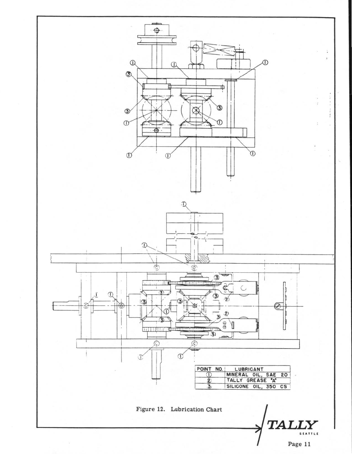
REEL DRIVE
BELT
L.H. /
-CABLE CONNECTOR r DRIVE MOTOR
, F
USE
MOTOR CHASSIS
C
APACITOR
\ -CAPSTAN
I
l)RIVE
BELT
1-REEL DRIVE
BELT
R.H.
REEL
DR
I
VE
--
MECHANl
SM
LH
.
i...
,--·-
0
~·
~
L
' .....1-.
I
1-4
:
I~
I
...
..
-·---r 1_ I
~
I I
'--4
...
,
"":------'-...J...
~
_.J
: I
l
·,
;
.,
I I
·1
I
\ j I
!.r---------
-
--'J
.
ri
\
~
I • I
__
l
___
J I
---·--
--
-
·
·-
--
---,.-----
------
-"!--"t:===='i"I-
---
----,-,-------~
~
r"--
-
----
-
'·
v··
·-
----
.'
__
,r
--
=,
--·-
! i I -
~~-~"""""~==========~===--...,1
-:-
·-
---:_
____
...-
__
.......
""""
r
-===:=:!!!~~==~~====~====~'===
====
/ \ \
LIFT
LEVER
\-
TAPE
TAPE
TENSION
ARM
~
REEL
READ HEAD
ASSEMBLY
~
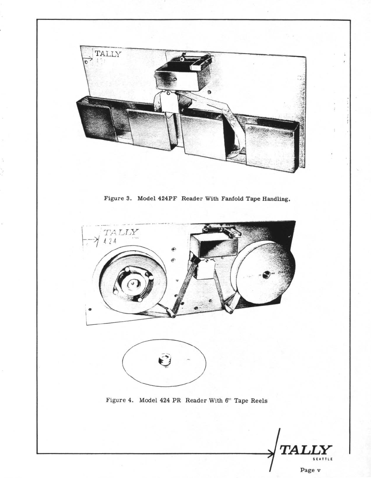
Figure
5. Model
424PR
Reader With 6"
Reels,
Plan
View
R.H.