Tamco Ranger Installer manual

Instruction Manual & Parts Catalogue
This radio control model is not a toy. Before using, please ensure you fully read and understand this manual.
The contents and specifications are subject to change without prior notice due to improvements and design changes.
Introduction
Item No: TAR0003
Ver 2013.1
WATERPROOF
ESC
540
MOTOR
2.4GHZ
RADIO
PRE
ASSEMBLED
OFF
ROAD
1:10TH
SCALE
Transmitter Battery Installation

Introduction
Thank you for purchasing this TAMCO RANGER 1:10 Brushed Truck. This radio control model car is not a toy and should be used under adult
supervision. The RANGER is equipped with the latest 2.4ghz radio equipment and a powerful brushed 20T motor along with a matched Electronic
Speed Controller. To ensure the safety of yourself and others, please ensure you read the manual fully before operating. Doing so will greatly reduce the
chance of an accident and help prolong the life of your model.
We hope you enjoy many hours of fun with your new model.
Safety Precautions
This product is not a toy, it is a high performance model that can operate at high speeds.
Adult supervision is necessary for children operating this model.
Avoid excessive amounts of water as this can effect the performance of the electronic components.
Before each use, please ensure you visually check your model and ensure all screws and bolts are tightened before you operate your model.
Please ensure you operate your model in a suitable enviroment away from traffic and other obsticles.
Remove the battery from the car when not being used for long periods of time.
Always disconnect the battery in between uses.
Avoid touching the motor and speed controller as these items can get hot while in use.
Avoid touching any moving parts.
Always charge the battery on a hard, non flammable surface.
Remove the battery from the car before charging.
Do not throw old battery packs into a fire. Always ensure you dispose of old batteries correctly.
Operational Precautions
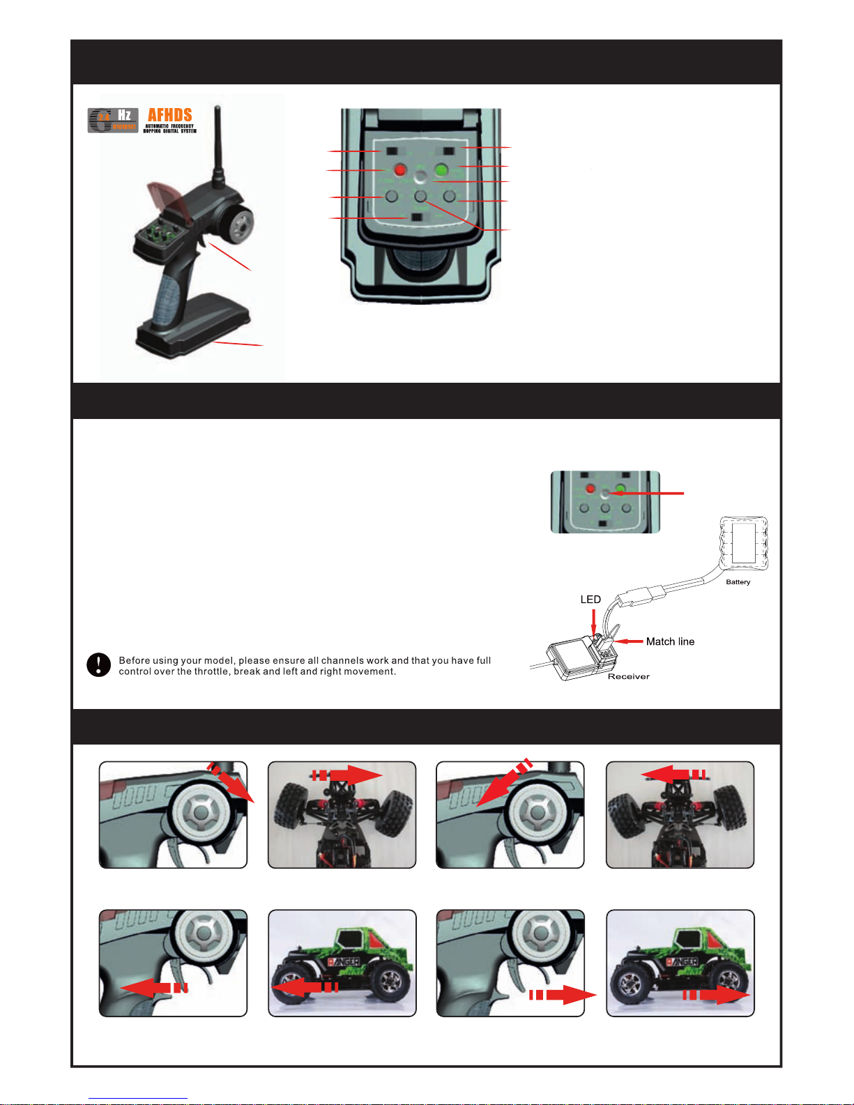
Always switch on the TRANSMITTER first, then the RECEIVER.
Always ensure you run your model in a spacious area, or at a dedicated track.
Avoid using your model near crowds, in the road or in limited space.
Always ensure your battery packs are fully charged before use to ensure optimal performance.
Always check that the transmitter and receiver are working correctly before operating fully.
Never “over rev” the car when not under load, i.e being held in the hand, as this can cause various mechanical failures.
Controls
Charging The Battery Pack
Remove the battery from the car before charging and place on a hard nonflammable surface.
Once the battery is ready to be charged, first plug the charger into the outlet of the AC power source
(with the switch in the off position), then connect the battery input/output connector to the charger.
When you switch the power on the red light will illuminate and continue
whilst charging, when charging is complete it will change to green.
The battery / charger included with this car will take approximately 12 hours to
charge. Do not leave the battery unattended.
As soon as the battery is fully charged switch of the power, unplug the charger
and disconnect the battery from the charger plug. Over charging or charging with
inadequate chargers may cause the battery pack to become very hot.
Ensure that the battery pack is completely discharged prior to charging, this can
be achieved by running the motor until it slows down.
For best results let the battery cool before charging, heat may prevent the battery
pack from charging to full capacity and also decreases the performance of the battery.
Charging must always be done by an adult, or under adult supervision.
Transmitter Battery Installation
Slide the battery cover off to access the
battery compartment.
Insert 8 x AA Batteries into the
compartment, taking care to
match the polarities.
Do not mix battery types or
old and new batteries.
Please ensure you dispose of any old
batteries correctly. 8 x AABatteries required.
Purchased separately
The TAGT2 features a charging jack which allows you to use rechargeable batteries in the transmitter.
Ensure you insert 8 rechargeable battery packs and follow the chargers instruction book.
Both the charger and the rechargeable batteries will need to be purchased separately.
When charging we recommend that the transmitter is placed on a hard, non flammable surface
and under constant supervision.

TAGT2 Transmitter
Features & Functions
1 - Transmitter Antenna
2- Steering Wheel
3 - Throttle/Brake Control
4- Steering Reverse Switch
5- Power LED
6- Steering Trim
7- Power Switch
8- Throttle Reverse
9- Power Check LED
10 - Bind Button
11 - D/R Trim
12 - Throttle Trim
13 - Battery Compartment
4
5
6
7
8
9
10
11
12
1
2
3
13
Binding Process
A binding feature is included with the TAGT2 Handset to ensure the transmitter and receiver bind properly and prevent interference from other
controllers. To bind your transmitter and receiver, please follow the steps below.
1- Install batteries (6 x AA, not Supplied) into the transmitter, but do not switch ON.
2- Insert the “match line” unit (supplied) into the Ch3/Bind port of the receiver.
3- Connect the receiver battery supply to the VCC port on the receiver and switch ON.
Now the 2 LED lights are flashing, awaiting signal.
4- Press and hold down the BIND button on the transmitter, then turn on the transmitter. (apx 5 secs)
5- Watch the flashing LED’s on the receiver until they stop. The Transmitter & Receiver are now matched.
6- Releae the BIND Button on the transmitter and remove the “match line” from the receiver.
7- Install servo cables.
8- Switch ON car first, then the TRANSMITTER.
9- Check that the binding process was sucssesful by moving the controls.
10 - If it has NOT worked, please repeat the stages above
BIND
Controls
Electronic Speed Controller
Basic Wiring Diagram

Electronic Speed Controller
Basic Wiring Diagram
Specification
input voltage(V)6V-8.4V DC
BEC output voltage(V)—current(A)6V—2A
Output Current Operating Current 40A Max 320A,
Backward 160A
Motor Above 540 17T
ESC Size 46.51 x 32.36 x 37.10mm
Operational Notes
Turn on Transmitter and connect battery.
Turn on the low voltage switch followed by the power switch, this will produce a red light and a
audible sound from the motor.
The ESC has a low voltage protection function, if the voltage of the battery drops to low the power
will cut off, if this happens turn off the car and transmitter and recharge battery.
If you remove have to remove the ESC unit for service or repair, please ensure you re connect the
battery connectors correctly by matching the polarities/colours.
Please Note. – The ESC and Motor can become hot if used constantly, if this happens disconnect battery
and ESC and allow them to cool down before continuing.
Receiver
Steering
Servo
E.S.C
Battery Pack
Motor

Replacement Parts
TAR511000
10T Bevel Gear Set TAR511002
11T Main Gear TAR511003
34T Bevel Gear TAR511004
Diff. Case Set
TAR511005
Gear Box Case TAR511020
Steering Post Set TAR511026
Shock Mounts TAR511028
Ball Head Nut
TAR511029
Pivot Ball Screws TAR511047
Suspension Arm Shaft Set TAR511051
Hex Adapter Set x 4
TAR511123
Antenna Pipe Set TAR511129
Body Clips x 10 TAR511311
13T Diff. Bevel Gear Set
TAR511484
FR Steering Hub Set x 2 TAR511686
Clear Motor Cover
TAR513005
RANGER Shock Tower Set TAR513006
Front Upper Suspension Arms
TAR511752
Charger Adapter Set
TAR511667
Receiver Box
TAR513007
Front Lower Suspension Arms TAR513008
Rear Lower Suspension Arms
TAR511180
Replacement 4kg Servo
TAR511114
20T Brushed Motor

Replacement Parts
TAR532002
Gear Mount Set TAR532003
Rear Main Gear Set TAR532004
Motor Mount Set
TAR532007
Steering Arm Set TAR532008
Centre Drive Shaft TAR532009
Metal Main Chassis
TAR532096
Servo Horn Set TAR532097
Servo Mounts TAR532098
Shock Stand Offs x 4
TAR538004
Drive Shafts x 2 TAR538013
11T Bevel Gear Set TAR538055
Servo Linkage Rods
TAR538056
Steering Turnbuckle Set
TAR513011
Red Metal Shock Set x 4
TAR533023
Rear Hub Carriers TAR538001
FR Lower Skid Plate TAR538002
Truck Bumper Set
TAR538003
Wheel Axle Set x 2
TAR538057
Rear Upper Rod Set TAR538106
Top Brace Set
TAR533000S
RANGER Wheels & Tyres x 2
TAR538058
ESC Set
TAR5xxxxx
RANGER Body Set
TAR532023
Motor Pinion

Overview
Replacement Parts
TAR581000
7mm E Clips x 6
TAR581002
4mm E Clips x 6 TAR581004
2.5mm E Clips x 6 TAR582002
10x15x4 Bearing x 4 TAR582004
5x11x4 Bearing x 6
TAR582005
5x10x4 Bearing x 6 TAR583009
M3x8 CS Screw x 8 TAR583010
M3x10 CS Screw x 8 TAR583013
M3x10 CS Screw x 8
TAR583015
M3x12 BH Cross Screw x 8 TAR583016
M3x8 BH Cross Screw x 8 TAR583097
M3x10 ST Cross Screw x 8 TAR583100
M3x8 BH Cross Screw x 8
TAR583104
M3x15 ST Cross Screw x 8 TAR583108
M3x10 BH Cross Screw x 8
TAR585000
2x11 Dowel Pin Set x 8 TAR585001
3x10 Dowel Pin Set x 8 TAR587001
M4 Nuts x 6
TAR583110
M3x12 CS Screw x 8 TAR584001
M3x3 Set Screw x 8
TAR584002
M4x4 Set Screw x 6
TAR538401
72T Main Diff Gear TAR538405
Drive Cup Set x 2 TAR539061
Battery Holder Set

TAR533000
Wheel & Tyre Set - Black
Please retain the packaging and this
manual for future reference
Replacement Parts
Overview
Steering Servo
20T Motor
Receiver Box
Steering Hub
Bumper
Shocks
Adjustable Turnbuckle
Speed Controller
Main Chassis Battery Pack
High Grip Tyres
Differential
TANB3000
3000mAH NiMh Battery
TAC010
NiMh Charger TAR511485
Large Pro Pull R Clips
TAR511487
Small Pro Pull R Clips TAR5xxxxx
RANGER Body Set - Black TAR5xxxxx
RANGER Body Set - Red


Table of contents
Popular Motorized Toy Car manuals by other brands

Helion
Helion Intrusion XLR HLNA0684 quick start guide

Radio Shack
Radio Shack Baja Banshee owner's manual

Gift in a Tin
Gift in a Tin Camper Van Construction Kit instructions

HPI Racing
HPI Racing CYCLONE instruction manual

Mega Bloks
Mega Bloks PROBUILDER RACING Tantalus Ti SRA 3722 instruction manual

Turnigy
Turnigy PLUSH-6A manual