Tanaka ACO-7 User manual

- 0 -
Cleveland Open Cup
Automatic Flash Point Tester
Model ACO-7
Asphalt Version with Data Memory
Instruction Manual
Rev.5.1 100414
IMPORTANT:
*This Manual contains important technical
information as wall as safety information.
*Read this Manual thoroughly before use, and
keep it for later use.
TANAKA SCIENTIFIC LIMITED

1
CAUTION
Handling for Fire Containment Lid of ACO-7
When Fire Containment Lid is not set in the proper place, it does not operate correctly.
1. To set it correctly, please push the Reset Knob which is located on the right side
Activated position
Reset Knob
Reset

2
2. How to check Correct position & Wrong position
Correct position Wrong position
Slit can be seen Slit cannot be seen
Hook is positioned inside of the catch Hook is positioned out of the catch

3
TABLE OF CONTENTS
FORWARD ……………………………………………………………………... 4
INTENDED READER OF THIS MANUAL …………………………………. 4
REVISIONS ……………………………………………………………...……... 4
SAFE OPERATION …………………………………………………………… 4
WARNING ……………………………………………………………………... 5
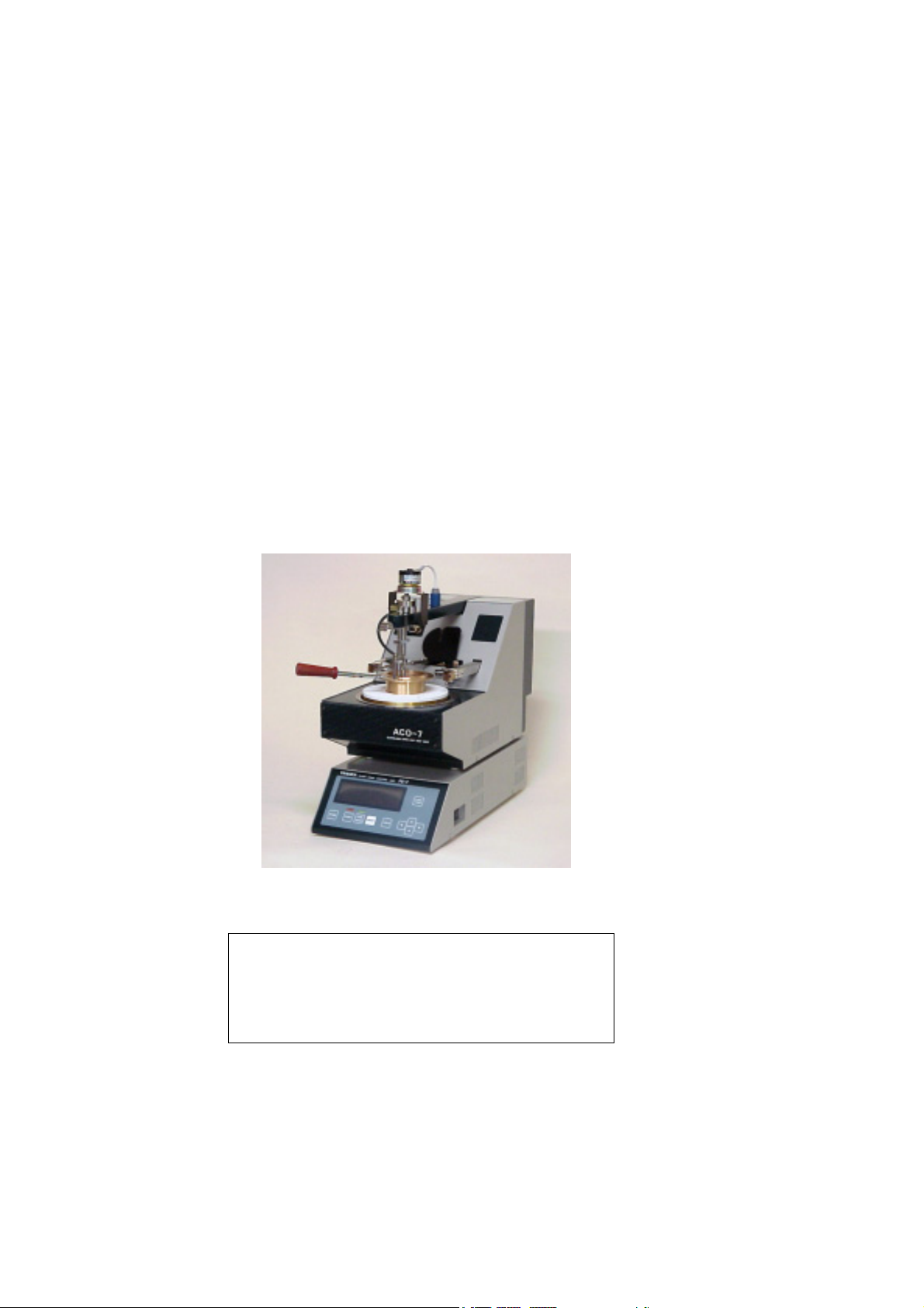
1. Overview of Model ACO-7 ………………………………………………..... 6
2. Installation …………………………………………………………………… 9
2.1 Installation Site …………………………………………………...………. 9
2.2 Electric Connections …………………………………………..………….. 9
2.3 Gas Connection ……………………………………..…………………….. 9
3. Operation ………..…………………………………………………………....11
3.1 Power ON …………………………………………………………………. 11
3.2 Cinfirming a Barometric Pressure Value ………………………………..11
3.3 Select Test Mode………………………………………………………….. 12
3.3.1 Normal mode ………………………………………………………….. 12
3.3.2 Special Mode ………………………………………………………….. 12
3.3.3 Fire Mode ………………………………………………………………12
3.3.4 Skim Mode ……………………………………………………………. 12
3.3.5 User’s Custom Mode …………………………………………………. 13
3.4 Test Procedure in Normal mode …………………………………………13
3.4.1 Setting of Expected Flash Point ……………………………………... 13
3.4.2 Preparation of Test Cup and Sample ……………………………….. 13
3.4.3 Test Start ……………………………………………………………… 13
3.4.4 Start of Ignition Source Application ………………………………... 14
3.4.5 Flash Detection ……………………………………………………….. 14
3.4.6 Completion of a Test …………………………………………………. 16
3.5 Test by Special Mode ……………………………………………………. 16
3.6 Test by Fire Mode ……………………………………………………….. 17
3.7 Test by Skim Mode ………………………………………………………. 17
4. Data Storage Function ……………………………………………………. 18
5. In Case of Abnormal Operation or Trouble ……………………………… 19
6. Safety ………………………………………………………………………… 19
6.1 Gas Piping ……………………………….……………………………….. 19
6.2 Prevention of Sample from Catching Fire ……………………………… 19
6.3 Manual Fire Containment ………………………………………………. 19
7. Post-sales Servicing ………………………………………………………… 20
8. Precaution in Case of Loss of Instruction Manual ………………………. 20
9. Caution when Transferring This Tester ………………………………….. 20
10. Specifications ………………………………………………………..…….. 20

4
FOREWORD
Thank you for purchasing model ACO-7.
This Instruction Manual includes necessary information for the installation/operation of ACO-7.
Please read this Manual thoroughly to understand the contents before installation and operation.
While all our products have been adjusted and inspected to our specification prior to shipment,
should any quality or specification concern arise, please contact Tanaka or its authorized
distributor.
INTENDED READER OF THIS MANUAL
This Manual has been intended to be read and understood by all those who operate ACO-7.
Also, it is assumed that the user have knowledge of handling of dangerous goods as well as related
industrial standard such as ASTM.
REVISIONS
The contents of this Manual may be subject to change without prior notice.
SAFE OPERATION
The following nomenclature to indicate the safety precaution have been used in this Manual.
WARNING : Indicates a potentially hazardous situation which, if not avoided, could
result in death or serious bodily injury.
CAUTION : Indicates a potentially hazardous situation which, if not avoided, may
result in minor or moderate bodily injury and/or property damages.
And also the WARNING LABELS are put on the body of ACO-7. The meaning of these labels is
as follows.
: GENERAL WARNING
: HOT
!
!
!

5
WARNING
Installation Site:
Install the Tester on a solid horizontal work bench with a provision of ventilation nearby or
inside a fume hood. The Tester needs to be placed at least 20cm away from other objects
Ambient temperature to be 10-30oC and humidity to be less than 90% (no condensation).
Power Source Voltage:
Supply a specified power source voltage. Turn the power on after all electric connection
are made.
Alteration:
Do not make any modification to the Tester, in whole or a part, or add any unauthorized
accessories to the Tester without prior consent by Tanaka Scientific Limited(hereinafter
referred to as Tanaka).
We can not take any responsibilities for damages, including but not limited to property
and/or bodily damages, associated with the alteration of Tester.
Maintenance:
Any repair on the Tester should be made by an authorized service technician appointed by
Tanaka.
For consumable, use only Tanaka genuine parts.
Use of This Tester for Other Purposes:
Use this Tester solely for its intended use of performing determination of the flash point of
petroleum products subscribed in such test standard as ISO 2592, ASTM D92 and IP 36.
Unattended Operation:
The specimen may catch a fire and blaze up. For the safety, it is essential that at least one
trained personnel be present in your test room, lab, etc. when testing.
In Case of abnormality:
Should any abnormality including abnormal noise or movement be observed, turn the
power off and contact Tanaka or its authorized distributor.
!

6
1. Overview of Model ACO-7 Asphalt Version
Fig. 1 External View of Model ACO-7 Asphalt Version
Motor for Skim
Stove Section
Test Flame Nozzle
Arm Handle
MAIN Switch
Dual Electric
Pilots
(Igniter Top)
Thermal
Insulation
Flame Size
Comparison Bead
Temperature
Sensor
Fire Containment Lid
Arm
Panel Sheet
Switch
Display
Test Cup
Needle Valve
For Test Flame
Dual Electric
Pilots
Heater Output
Indicator
Flash Detector Rings Thermofus
Skimmer
Shaft
Reset
Knob
Manual Fire Containment Switch

7
MAIN Switch:
Used for switching power source to the Tester.
Panel Sheet Switch:
Consists of START, COOL, RESET switches as well as switches for changing test parameters.
Display:
Displays test status and result as well as test parameters.
Flash Detector Rings:
Detects flash by ionization current between each rings.
Temperature Sensor:
Senses specimen temperature.
Needle Valve for Test Flame:
Adjusts test flame size.
Test Flame Nozzle:
Swings in a plane above the cup.
Arm:
Lift this arm up and hold the handle when you set the test cup.
Heater Output Indicator:
Blinks when the heater is turned on.
Dual Electric Pilots:
Igniter tops (nichrom filaments) turn on as a test starts to ignite the gas flame.
Stove Section:
Houses the electric heater assembly for specimen heating inside.
Thermofuse:
Detects blaze up of specimen.
Flame Size Comparison Bead:
Adjust the test flame to the size of this bead.
Fire Containment Lid:
Activates automatically to help putting out fire when Tester detects a fire point or
specimen is burning up heavily.
Reset Knob
Push this knob when resetting the fire containment lid.
Manual Fire Containment Switch (See 6.3):
Push this switch when operator wants to activate fire containment lid manually.

8
Fig. 2 Operation Panel and Display of Control Unit
(1) Fluorescent Display:
Displays test mode, specimen temperature, flash point (when blinking), expected flash
point, trouble message, etc..
(2) RUN Lamp:
Illuminates when a test process is in progress.
(3) COOL Lamp:
Illuminates when cooling.
(4) MODE Switch:
Changes the test mode.
(5) START Switch:
Starts a test.
(6) COOL/WARM Switch:
This key have only function of cool, used for manual cooling.
(7) RESET Switch:
Used for stopping a test, stopping a cooling and changing parameters.
(8) CHECK Switch:
Used for manually applying the ignition source or for checking fire containment lid
function.
(9) Left-Right Keys:
Used for moving cursor.
(10) Up-Down Keys:
Used for increasing/decreasing numeric figures.
(11) FUNCTION Key:
Used for changing screen.
MODE START
COOL
WARM RESET CHECK
RUN
FUNC
TION
(1)
(3)(2)
(4) (5) (6) (8)
(11)
(9)
(7)
(10)

9
2. Installation
2.1 Installation Site
Install the Tester on a draft-free, level and stable table. The Tester needs to be placed at least 20cm
away from other objects.
The following locations should be avoided as the installation site:
- An area with high temperature and/or high humidity
- An area exposed to direct the sun
- An area with poor ventilation and/or dusty air
- An area subject to rapid changes in ambient temperature
2.2 Electric Connections (Fig. 3)
WARNING To prevent electric shock hazard, be sure the grounding wire is
connected.
Do not ground to gas pipe; fire or explosion may result.
The grounding wire may be connected to one of the following:
- The ground terminal of the power outlet
- Copper wire buried at least 65cm deep in the earth
- Metallic water pipe line appropriate for use as electric
grounding
(1)Confirm the voltage of the serial number label located left side of Control Unit
and your electric source.
(2)Connect the Control Unit and the Test Unit with Signal Connecting Cable.
(3)Connect the power connecting cable of Control Unit to the Test Unit.
(4)Plug in the AC power code of the Control Unit to an electric outlet. Be sure to get grounding to
prevent an accident.
2.3 Gas Connection
WARNING The maximum gas pressure should be lower than 9.8 kPa.
Using the rubber hose supplied for gas, connect the gas source (LP gas or Natural gas) and the gas
inlet nipple on the rear panel of the Test Unit. Then fasten both ends with hose bands. See Fig. 3.
!
!

10
Fig. 3 Rear View and Electric Connection
Power Connecting Cable
AC Power Cord
Signal Connecting Cable
RS-232C Connector
Circuit
Protector
AC Outlet
Gas Inlet
Test Unit
Control
Unit

11
3. Operation
3.1 Power ON
Turn the MAIN switch ON. A message screen as illustrated in Fig. 4 appears on the control Unit
display.
Fig. 4 Main Screen
3.2 Confirming a Barometric Pressure Value
ACO-7 is capable of making automatic correction for barometric pressure by built-in barometric
pressure sensor. Confirm the barometric pressure every morning as follows:
(1) Press FUNCTION key, The display shows Baro set screen as illustrated in Fig. 5 appears.
(2) If the barometric pressure is not matched to calibrated barometer, calibrate barometric pressure
sensor. Refer ACO-7 Maintenance Manual for the calibration.
Fig. 5 Barometric Pressure Entering Screen
*Fire Containment Lid function can be tested by pressing CHECK switch.
ACO
TEMPERATURE EXP.FP
270
ASTM
oC
23.4
Model T
yp
e
Expected
Flash Point
Metho
d
& Mode S
p
ecimen Tem
p
erature
ACO
Baro set(hPa)
1013
Prev.FP 137.0 CHECK
->
Damper

12
3.3 Select Test Mode
ACO-7 Asphalt version has 2 kinds of test method and 5 kinds of test mode. Each ASTM and ISO
method has each Normal mode, Special mode(Fast Search), Fire mode, Skim mode and User’s
Custom mode. Fire mode and User’s Custom mode are invalid when shipping. The test method
(ASTM or ISO) is selectable by changing DIP switch on the MAIN board. See Maintenance
Manual for ACO-7.
Press the MODE switch to select test mode.
Display Method & Mode
ASTM
ASTM Normal mode (Flash point only)
ASTM
SPE
ASTM Special mode (Flash point only)
ASTM
Fire
ASTM Fire mode (Flash & Fire Point)
ASTM
SKIM
ASTM Skim mode mode
ASTM
User
ASTM User’s Custom mode
ISO
ISO Normal mode (Flash point only)
ISO
SPE
ISO Special mode (Flash point only)
ISO
Fire
ISO Fire mode (Flash & Fire Point)
ISO
SKIM
ISO Skim mode
ISO
User
ISO User’s Custom mode
3.3.1 Normal Mode
In this mode, the test proceeds until flash detection in accordance with ASTM D92 or ISO
2592(IP36).
3.3.2 Special Mode
This mode is used for measuring the approximate flash point of a sample of unknown expected
flash point. The Special mode starts the test flame application at the every 2 oC (5 oF )from the test
start, and thus it is different from the Normal mode.
3.3.3 Fire Mode
In this mode, the test proceeds until fire point after flash detection in accordance with ASTM D92
or ISO 2592(IP36).
3.3.4 Skim Mode
This mode is used for measuring the flash point of bitumen which forms surface film.

13
Automatic surface film skimmer works to attain the right test result when the setting temperature is
reached.
For the starting temperature and interval setting of skimmer, see 3.7.
3.3.5 User’s Custom Mode
In this mode, heating rate, stirring speed, application interval and its start temperature can be
changed by operator.
3.4 Test Procedure in Normal Mode
3.4.1 Setting of Expected Flash Point
WARNING The sample may catch a fire, if an erroneous expected flash
point was set.
The expected flash point is displayed in a three-digit figure below the EXP.F.P on the right end of
the display. When altering the expected flash point, press the Right-Left key to move the cursor,
and after that, operate the Up-Down keys. No numeric figures above 400 (760 in oF) can be set.
3.4.2 Preparation of Test Cup and Sample
(1) Wash the test cup with the cleaning solvent to remove any test specimen or traces of gum or
residue remaining from a previous test. When the upper side of cup’s flange is covered with
carbon deposit, the flash detector cannot operate normally. Also when conductive material
adheres to the insulator of electrode ring (outer ring), bad insulation can cause mis-detection of
flash. Therefore, keep the parts cleanly.
(2) When testing samples of very viscous materials and containing dissolved or free water, follow
Sampling section of ASTM D92.
(3) Fill the test cup with the sample so that the top of the meniscus of the test specimen is exactly at
the filling mark
(4) Push up the arm handle and place the test cup on the center of the heater
(5) Lower the arm gently until stopper is touching the flange of the cup.
Now you have completed the preparation for the test.
3.4.3 Test Start
WARNING Toxic gas may generate as a result of decomposition of specimen
in the course of heating. Provide adequate ventilation.
Specimen may catch fire in the course of a test. Place a fire
extinguisher near the Tester. Also, do not leave the Tester
unattended.
Press the START switch; RUN lamp illuminates, and the test starts. The expected flash point (*1)
is displayed for 5 seconds, dual electric pilots light up and specimen heating starts.
Test flame is ignited by electric pilots automatically. Adjust the test flame to 4mm in diameter (the
flame size comparison bead size) by needle valve.
The test proceeds automatically hereafter.
!
!

14
*1:The setting of the expected flash point is changeable even during the test. After
changing in accordance with Section 3.4.1, re-press the START switch. Also in this
case, the newly set expected flash point appears in the center of the display for 5
seconds.
3.4.4 Start of Ignition Source Application
After the test starts, the specimen temperature rises at a rate of 14 to 17 oC /min(25 to 30 oF /min).
When the temperature reaches 56 oC (100 oF) below the expected flash point, the heating rate is
decreased so that the rate of temperature increase during the last 28 oC (50 oF) before the expected
flash point is 5 to 6 oC(9 to 11 oF). When the temperature of the test specimen is 28 oC(50 oF) below
the expected flash point, the test flame begins to apply. After that, the application operation is
repeated at each 2 oC(5 oF).
3.4.5 Flash Detection
(1) When the flash is detected, the observed flash point is corrected by barometric pressure and
rounded (*2, recorded flash point) and then starts flashing. See Fig. 6.At the same time buzzer
beeps intermittently for 8 seconds. Furthermore, the solenoid valve for gas is closed, the test
flame goes out and electric pilots go off and the stove section starts cooling down. (The COOL
lamp lights up.)
Fig. 6 Flash Point is Detected Normally
*2: The corrected flash point (Fc) is computed automatically by using the following formula,
rounded to the nearest 1 oC(2 oF) when ASTM is selected as a test method,
rounded to the nearest 2 oC when ISO is selected as a test method and then displayed.
For the selecting test method (ASTM or ISO), refer ACO-7 Maintenance Manual.
Fc=F+0.025(1013-P1)
where Fc: Corrected flash point
F: Observed flash point
P1: Entered (detected) barometric pressure value (hPa).
or
Fc=F+0.06(760-P)
where Fc: Corrected flash point (oF)
F: Observed flash point (oF)
P : Entered (detected) barometric pressure value (mmHg).
ACO
FLASH POINT EXP.FP
CORRECTED
270
ASTM
oC
271.0
Flash Point
(
flashin
g)

15
Observed flash point can be seen by pressing FUNCTION key.
In case a wrong pressure value has been entered, enter the right value and then press
FUNCTION key; recalculated flash point will be shown.
(2) When ASTM is selected as a test method, and a flash point is detected at first application of the
ignition source, NG 1st appears right side of flash point. See Fig. 7.
(3) When ISO is selected as a test method and the temperature at which the flash point is observed
is less than 18 oC from the temperature of the first application of the test flame, NG XX
(XX = observed flash point – first application) appears right side of flash point. See Fig. 8.
In this case, alter the expected flash point and restart the test.
Fig. 7 Flash Point is Detected at First Application (ASTM method)
Fig. 8 Flash Point is Detected invalid temperature (ISO method)
ACO
FLASH POINT EXP.FP
CORRECTED
270
ASTM
oC NG 1st
242.0
NG appears
Flashed at 1st application
ACO
FLASH POINT EXP.FP
CORRECTED
270
ISO
oC NG 12
254.0
NG appears
Observed flash point - First application = 12 oC

16
(4) If the flash point has not been detected when the safety cut temperature (expected flash point
+30 oC(+60 oF) or 400 oC(760 oF)) is reached, the display will be as Fig. 9, indicating the safety
cut temperature. Then, the heating will stop.
Fig. 9 Safety Cut Screen
3.4.6 Completion of a Test
WARNING If test cup is still hot after cooling is finished, do not touch
except arm handle without wearing gloves.
Be careful when handling the hot specimen. It may flash or
explode, if you disposed it to waste tank containing waste with
low flash point.
The cooling fan stops (the COOL lamp goes off) in 10 minutes (*3) after the flame detection. One
cycle of a test is completed at this moment and you can start the next test. When further cooling is
required, press the COOL switch. Cooling is available for another 10 minutes (*3).
The temperature display (flash point) is held until the RESET or START switch is pressed.
*3: Cooling time is adjustable. Also selectable (do cooling or not). For changing
cooling time, consult Tanaka authorized distributor.
3.5 Test by Special (Fast Search) Mode
This mode is used for measuring an approximate flash point of a specimen of unknown expected
flash point. The mode starts the ignition source application (at each 2 oC(5 oF)) from the test start.
Other than the test flame application, all the rest of the test procedure is the same as the Normal
mode. The following shows only differences from Normal mode. See Section 3.4.1 to 3.4.6 also.
ACO TROUBLE
FLASH POINT >
380
oC
Temp 386.7
!
Present Temperature
Safety Cut Temperature (EXP.FP+30
oC or 400 oC)

17
3.6 Test by Fire Mode
WARNING Fire Containment Lid and pivot shaft be kept clean to function
properly. Do the damper check before testing by fire mode.
As some fire may not be extinguished completely by the Fire
Containment Lid, the operator may have to extinguish the fire
manually. Prepare fire-resistant gloves and other necessary
objects to protect against burns.
Use knob when resetting the fire containment lid.
The following shows only differences from Normal mode. See Section 3.4.1 to 3.4.6 also.
(1) When the flash point is detected, the buzzer beeps and the RUN lamp flashes. At this point, test
flame application at the 2 oC (5 oF) interval is suspended to prevent accidental fire. Pressing the
START switch while the RUN lamp is flashing will stop the buzzer, and the test is continued
until the fire point detection. If the START switch is not pressed within one minute, the test is
terminated and the cool down cycle is initiated.
(2) Once flash detector detects 5 seconds of continuous burning (or press START switch by visual
determination), the fire containment lid activates automatically to help putting out fire. The
flash point and fire point is displayed (flashing alternately every 5 seconds), thus concluding
the test cycle.
(3) The operator must confirm that the fire containment lid has extinguished burning inside the
cup.
(4) The operator press COOL switch to start the sample cooling process.
(5) The operator carefully reset the fire containment lid after cooling is finished. Please use caution
resetting the fire containment lid as it possibility may be hot to touch. To reset, push the knob
straight back until latches and turn lid up.
3.7 Test by Skim Mode
The following shows only differences from Normal mode. See Section 3.4.1 to 3.4.6 also.
(1) To change start temperature and interval of skimmer, press the FUNCTION switch to change
the screen, then press the Right-Left key to move the cursor, and after that, operate the
Up-Down keys.
(2) Press the RESET switch to return the main screen after setting of skimmer.
(3) Attach a paddle to skimmer shaft.
(4) Automatic surface film skimmer works to when the setting temperature is reached.
Fig. 10 Skimmer Setting Screen
Skimmer can be worked not only automatically but also manually by pressing MODE key during a
test.
ACO
Baro(hPa) SKIM
1013
Start Interval
300
oC
10
oC
Prev.FP 137.0
!

18
4. Data Storage Function (use this function with optional Built-in Clock Board)
ACO-7 has a data storage function. Up to 50 successive data can be memorized. (*4)
After ACO-7 detects a flash point, the data will be stored automatically.
If Built-in Clock Board is not installed, actual date will not be memorized in DATE column.
The recalling procedure is as follows.
Press the MODE switch and RESET switch, then consecutively release the RESET switch and
then the MODE switch. The following screen will appear:
Fig. 10 Data Recall Screen
By pressing Up-Down key, the screen will be scrolled.
If needed, press FUNCTION key to print out all data. (when optional printer is connected)
*4: Following data will not be stored.
-used fire mode, special mode and user custom mode
-flash is detected at first application
-flash is detected by manual application
-
(New Data)
(Old Data)
ACO
DATA SAMPLE ID FLASH.P
01 03/14 09 LUBE 01 244.0oC
02 03/13 18 ST-AS 312.0oC
03 03/13 17 BL-AS 338.0oC
Month Day Hour Sample ID Corrected
Flash Point
Number
01: latest
50: oldest

19
5. In Case of Abnormal Operation or Trouble
CAUTION If even a “minor” abnormalit
y
is detected, stop usin
g
the Tester
immediately and consult Tanaka authorized distributor.
When a problem occurs on the Tester, a buzzer will sound and one of the trouble messages in Tab.
1 will be shown. When one of these events occurs, all output will be shut off. For troubleshooting,
consult Tanaka authorized distributor.
Tab. 1 Trouble Messages
Trouble Message on Display Buzzer
Control computer
runs away None Beeps continuously
Temperature sensor
is found defective
TROUBLE
TEMP SENSOR
Beeps intermittently for
eight (8) seconds
Flash detector is
found defective
TROUBLE
FLASH DETECTOR
Beeps intermittently for
eight (8) seconds
Flash detector detects
“fire” without “Fire
mode”
TROUBLE
FIRE? (by detector)
Beeps intermittently for
eight (8) seconds
Built-in battery has
expired
TROUBLE
REPLACE BATTERY
Beeps intermittently for
eight (8) seconds
Arm is not set in
place
TROUBLE
ARM POSITION
Beeps intermittently for
eight (8) seconds
Thermofuse is blown
TROUBLE
THERMOFUSE BLOWN
Beeps big sound
continuously
6. Safety
6.1 Gas Piping
Gas piping inside the Test Unit is made of nylon tube; outside, viton tube. Gas is very dangerous if
it leaks. Consult the Tanaka authorized distributor for periodical gas leakage check. THE
TESTER IS NOT EQUIPPED WITH A GAS LEAKAGE DETECTOR.
6.2 Prevention of Sample from Catching Fire
In case the temperature at which the first test flame application is made is above the flash point of
the specimen, there is a danger: the specimen catches a fire to blaze up.
So as to prevent such a danger in advance, for testing a sample of unknown flash point, use the
Special mode in Section 3.5. Be sure to arrange at least one proper person in your test room, lab,
etc., when testing, to cope with possible accidents.
6.3 Manual Fire Containment
In case the specimen catches a fire unexpectedly, push manual fire containment switch to
extinguish a fire. Push once more to stop buzzer, and then push RESET key to return MAIN screen.
!
Table of contents