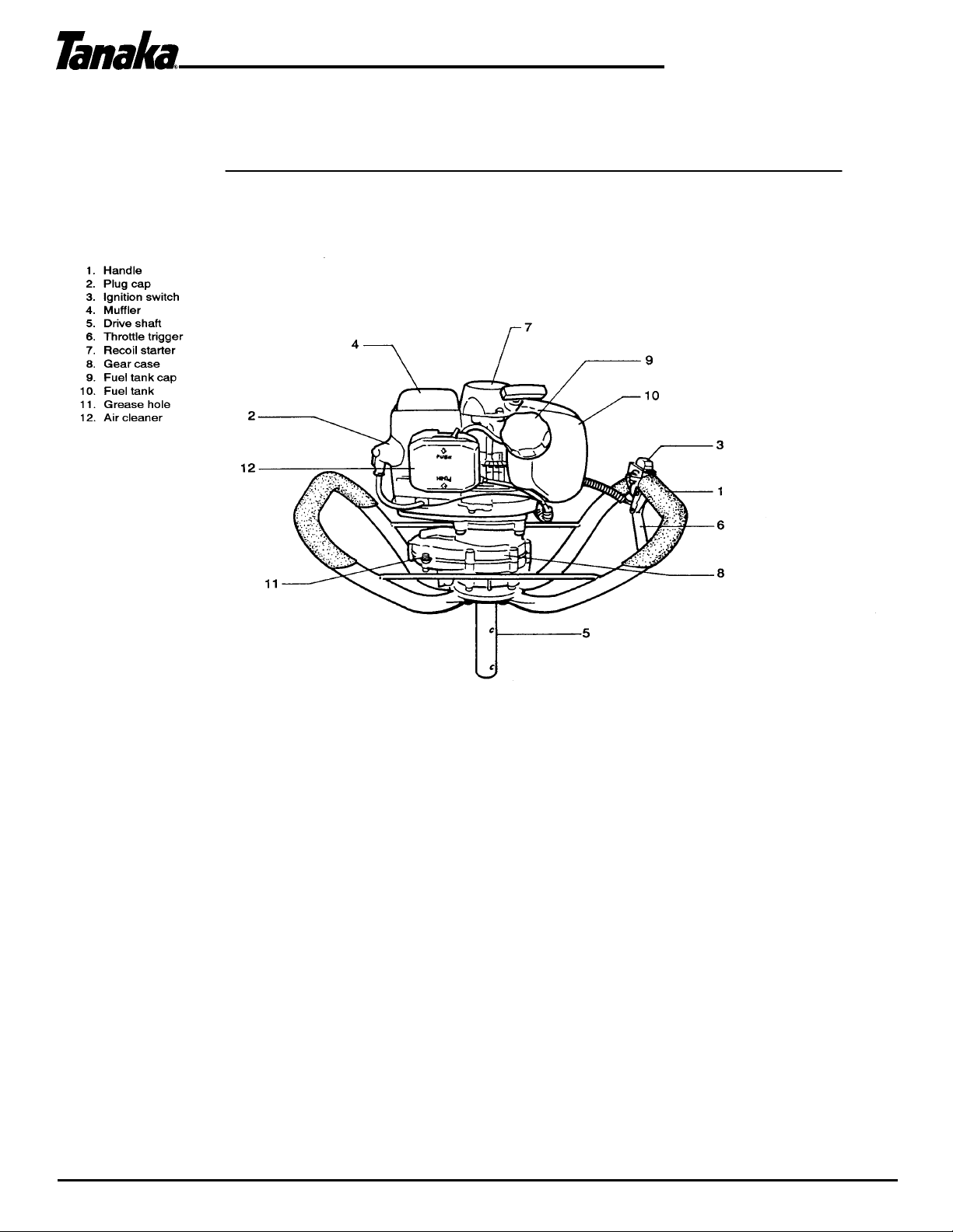
Tanaka TIA-340 User manual

Owner’Owner’
Owner’Owner’
Owner’s Mans Man
s Mans Man
s Manualual
ualual
ual
Model Numbers:
TIA-340TIA-340
TIA-340TIA-340
TIA-340
AA
AA
AUGERUGER
UGERUGER
UGER
P/N 30063
Date 04-20-01
Supplier To The Outdoor Power Equipment Industry
PARKLANDS Trading Co P/L • 106 Belmore Rd • Riverwood, NSW 2210 • Ph: (02) 9584-7700 • Fx: (02) 9153-9122 • Eml: [email protected]

1
Owner’s Manual
TIA-340
Before using this unit:
• Read the operator’s manual carefully.
• Check that the cutting equipment is correctly assembled
and adjusted.
• Start the unit and check the carburetor adjustment.
See “Maintenance”.
WARNING
Read, understand and follow all
warnings and instructions in this
manual and on the unit.
Always wear eye, head and ear
protectors when using this unit.
It is important that you read, fully understand and
observe the following safety precautions and
warnings. Careless or improper use of the uni
t
may cause serious or fatal injury.
The engine exhaust from this product
contains chemicals known to the State
of California to cause cancer, birth
defects and other reproductive harm.
Explains choke position.
Upper sigh indicates chose
closed and the lower fully
open.
Do not touch bit when running the engine.

2
Owner’s Manual
TIA-340
1. What is what ?
Since this manual covers several models, there may be some difference between pictures and your unit. Use the
instructions that apply to your unit.

3
Owner’s Manual
TIA-340
2. Warnings and safety instructions
Operator safety
• Always wear a safety face shield or goggles.
• Always wear heavy, long pants, boots and
gloves. Do not wear loose clothing, jewelry,
short pants, sandals or go barefoot. Secure
hair so it is above shoulder length.
• Do not operate that tool when you are tired,
ill or under the influence of alcohol, drugs or
medication.
• Never let a child or inexperienced person
operate the machine.
• Wear hearing protection.
• Never start or run the engine inside a closed
room or building. Breathing exhaust fumes
can kill.
• Keep handles free of oil and fuel.
• Keep hands away from drilling equipment.
• Do not grab or hold the unit by the drilling
equipment.
• When the unit is turned off, make sure the
drilling attachment has stopped before the
unit is set down.
• When operation is prolonged, take a break
from time to time so that you may avoid
possible whitefinger disease which is caused
by vibration.
Tool safety
• Inspect the entire tool before each use.
• Replace damaged parts. Check for fuel
leaks and make sure all fasteners are in
place and securely fastened.
• Replace parts that are cracked, chipped or
damaged in any way before using the tool.
• Keep others away when making carburetor
adjustments.
• Use only accessories as recommended for
this tools by the manufacturer.
WARNING!
• Never modify the tool in any way. Do not use
your drilling tool for any job except that for
which it is intended.
Fuel safety
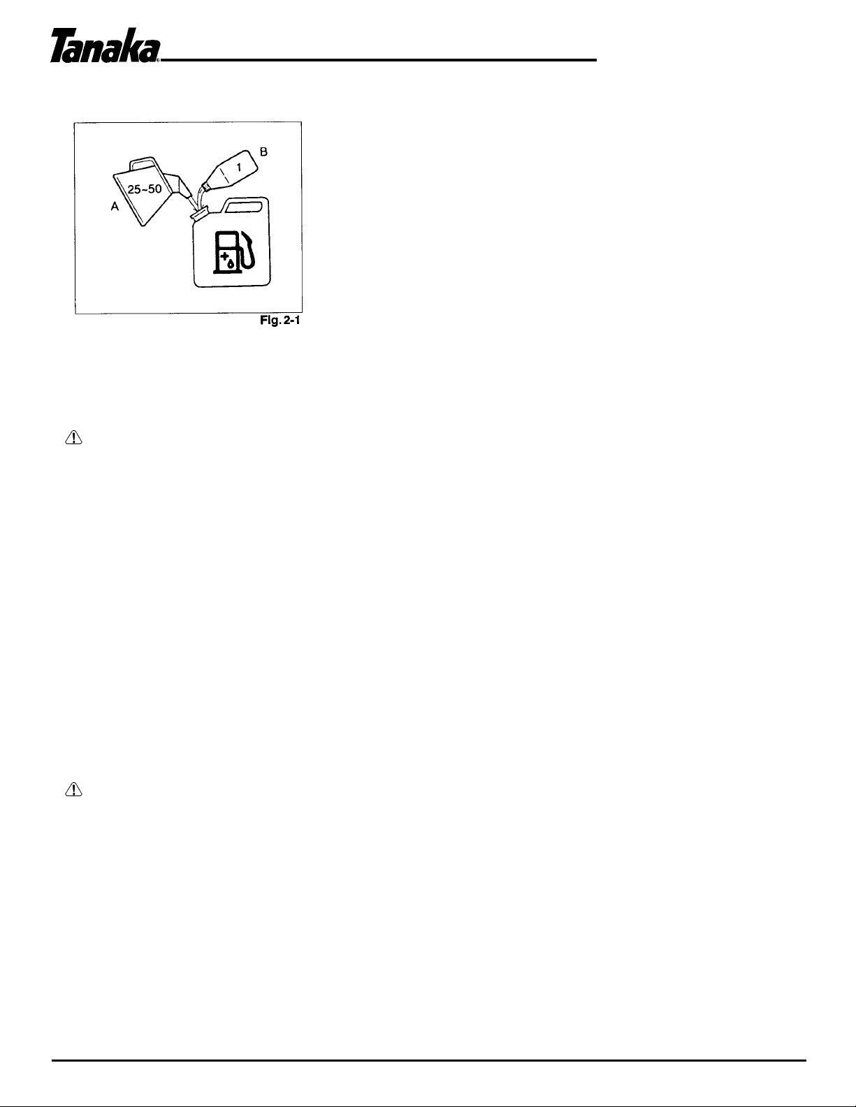
• Mix and pour fuel outdoors and where there
are no sparks or flames.
• Use a container approved for fuel.
• Do not smoke or allow smoking near fuel or
the tool or while using the tool.
• Wipe up all fuel spills before starting engine.
• Move at least 3 m (10 ft.) away from fueling site
before starting engine.
• Stop engine before removing fuel cap.
• Empty the fuel tank before storing the tool. It
is recommended that the fuel be emptied
after each use. If fuel is left in the tank, store
so fuel will not leak.
• Store tool and fuel in area where fuel vapors
cannot reach sparks or open flames from
water heaters, electric motors or switches,
furnaces, etc.
WARNING!
• Antivibration systems do not guarantee that
you will not sustain whitefinger disease or
carpal tunnel syndrome. Therefore, continual
and regular users should monitor closely the
condition of their hands and fingers. If any of
the above symptoms appear, seek medical
advice immediately.
Drilling safety
• Do not drill any material other than that for
which is intended.
• Inspect the area to be drilled before each
use. Remove objects which can be thrown
or become entangled.
• For respiratory protection, wear an aerosol
protection mask when drilling the area after
insecticide is scattered.
• Keep others including children, animals,
bystanders and helpers outside the 5 m (17 ft.)
hazard zone. Stop the engine immediately if
you are approached.
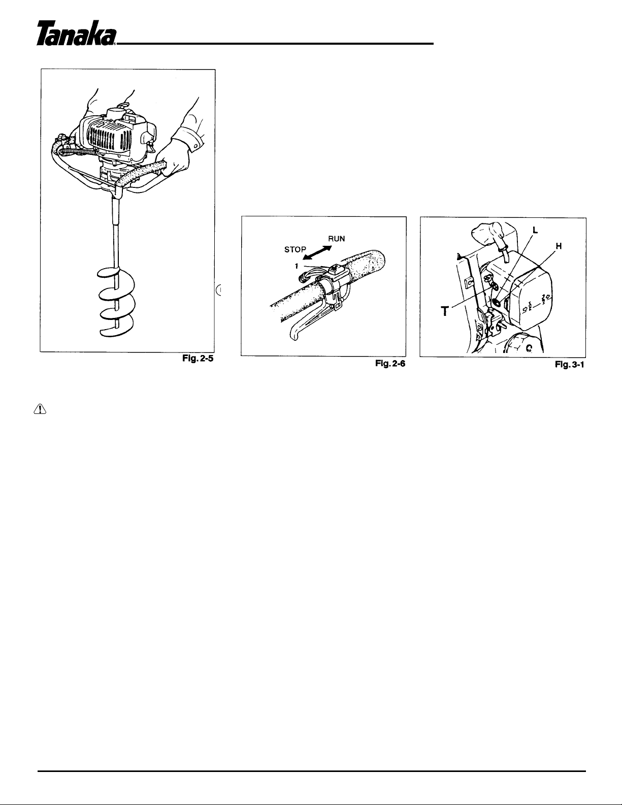
• Hold the tool firmly with both hands.
• Keep firm footing and balance. Do not
over-reach.
• Keep all parts of your body away from the
muffler and drilling attachment when the
engine is running.
Maintenance safety
• Maintain the tool according to recommended procedures.
• Disconnect the spark plug before performing maintenance
except for carburetor adjustments.
• Keep others away when making carburetor adjustments.
• Use only genuine replacement parts as recommended by the
manufacturer.
Transport and storage
• Carry the tool by hand with the engine stopped and the
muffler away from your body.
• Allow the engine to cool, empty the fuel tank, and secure the
tool before storing or transporting in a vehicle.
• Empty the fuel tank before storing the tool. It is
recommended that the fuel be emptied after each use.
If fuel is left in the tank, store so fuel will not leak.
• Store tool out of the reach of children.
• Clean the unit carefully and store it in a dry place.
• Make sure engine switch is off when transporting or storing.
• When transporting in a vehicle, cover bit with bit cover or rug.
• If situations occur which are not covered in this
manual,take care and have good judgment.
Contact your dealer if you need assistance.
• Pay special attention to statements preceded
by the following words:
WARNING!
• Indicates a strong possibility of severe personal injury or
loss of life, if instructions are not followed.
CAUTION!
• Indicates a possibility of personal injury or
equipment damage, if instructions are not
followed.
NOTE!
• Helpful information for correct function and use.

4
Owner’s Manual
TIA-340
3. Operating procedures
Fuel (Fig. 2-1)
WARNING!
The power auger is equipped with a two-stroke engine. Always run the engine on fuel, which is mixed with
oil. Provide good ventilation, when fueling or handling fuel.
Fuel
• Always use branded 89 octane unleaded gasoline.
• Use Tanaka two-cycle oil or a quality two-cycle oil at mixing ratio of 25-50:1 (Gasoline (A) : Oil (B)), only for the
state of California at 50:1.
• Never use multi-grade oil (10 W/30) or waste oil.
• Always mix fuel and oil in a separate clean container.
Always start by filling half the amount of fuel, which is to be used. Then add the whole amount of oil. Mix (shake)
the fuel mixture.
Add the remaining amount of fuel.
Mix (shake) the fuel-mix thoroughly before filling the fuel tank.
Fueling
WARNING!
• Always shut off the engine before refueling.
• Slowly open the fuel tank, when filling up with fuel, so that possible over-pressure disappears.
• Tighten the fuel cap carefully, after fueling.
• Always move the trimmer at least 3 m (10 ft.) from the fueling area before starting.
Before fueling, clean the tank cap area carefully, to ensure that no dirt falls into the tank.
Make sure that the fuel is well mixed by shaking the container, before fueling.

5
Owner’s Manual
TIA-340
4. Assembly procedures
Assembling (Fig. 1-1)
Connect the bit to drive shaft (1) of the power head and
fix it with the snap pins (2) after setting the fixing pins
(3) and washers (2 pcs. each).
Selection of a Suitable Bit
Choose an auger bit according to material to be bored.
In case of ice boring, use an ice bit. When boring the
earth, use one for earth boring.
Starting
1. Set ignition switch (1) to (RUN) position. (Fig. 2-2)
2. Pull the throttle trigger (2) and keep pushing the throttle lock (3), then slowly release the lever to be locked. (Fig. 2-2)
3. Set choke lever to (CHOKED) position. (Fig. 2-3)
4. Pull the recoil starter handle briskly, taking care to keep the handle in your grasp; and not allowing it to snap back.
(Fig. 2-4)
5. Once the engine is running, move the choke to the run-position. (Fig. 2-3)
NOTE!
At this stage if engine does not start, repeat procedure from 2 to 4.
6. After starting the engine, allow the engine about 2-3 minutes to warm up before subjecting it to any load.

6
Owner’s Manual
TIA-340
Drilling (Fig. 2-5)
Do not touch the bit when running the engine to avoid unexpected accident. Be sure to turn off the
ignition switch before touching it.
1. Hold the handle firmly with both hands so that you may not be swung by the unit.
WARNING!
2. Locate the edge of bit right on the spot to dig, and then drive the bit.
This is an easy job thanks to the built-in centrifugal clutch.
3. Stop the engine and inspect the unit if abnormal vibration or noise is generated.
Stopping (Fig. 2-6)
Gradually decrease the engine speed to an idle speed, and then slide ignition switch (1) to STOP
position.
4. Long operation of the unit may tire you. Try to take a break from time to time.

7
Owner’s Manual
TIA-340
WARNING!
The bit may be spinning during carburetor adjustments.
WARNING!
Never start the engine without the complete clutch cover and gear case assembled!
Otherwise the clutch can come loose and cause personal injuries.
In the carburetor, fuel is mixed with air. When the engine is test run at the factory, the carburetor is basically
adjusted. A further adjustment may be required, according to climate and altitude. The carburetor has one
adjustment possibility:
T = Idle speed adjustment screw.
Idle speed adjustment (T)
Check that the air filter is clean. When the idle speed is correct, the bit will not rotate. If adjustment is
required, close (clockwise) the T-screw, with the engine running, until the bit starts to rotate. Open
(counter-clockwise) the screw until the bit stops. You have reached the correct idle speed when the engine
runs smoothly in all positions well below the rpm when the bit starts to rotate.
If the bit still rotates after idle speed adjustment, contact your service workshop.
NOTE! (Fig. 3-1)
The standard openings (returns) of L/H screws from lightly seated positions are as follows.
WARNING!
When the engine is idling the bit must under no circumstances rotate.
5. Maintenance
MAINTENANCE, REPLACEMENT, OR REPAIR OF THE EMISSION CONTROL DEVICES AND SYSTEMS
MAY BE PERFORMED BY ANY NONROAD ENGINE REPAIR ESTABLISHMENT OR INDIVIDUAL.
NOTE FOR THE US MARKET!! (Fig. 3-1C)
We would like to inform that the power augers TIA-340
of the US model, which carry the following label on the
unit are different from ones for other market in
carburetor adjustment. Adjustment of Standard openings
of L/H screws are not necessary.
Carburetor adjustment (Fig. 3-1, 1 B)

8
Owner’s Manual
TIA-340
Air filter (Fig. 3-2, 2B)
The air filter must be cleaned from dust and dirt in order to avoid:
• Carburetor malfunctions.
• Starting problems.
• Engine power reduction.
• Unnecessary wear on the engine parts.
• Abnormal fuel consumption.
Clean the air filter daily or more often if working in exceptionally dusty areas.
Cleaning the air filter
Remove the air filter cover and the filter. Rinse it in warm soap suds. Check that the filter is dry before
reassembly. An air filter that has been used for some time cannot be cleaned completely. Therefore, it must
regularly be replaced by a new one. A damaged filter must always be replaced.
Spark plug (Fig. 3-3)
The spark plug condition is influenced by:
• An incorrect carburetor setting.
• Wrong fuel mixture (too much oil in the gasoline)
• A dirty air filter.
• Hard running conditions (such as cold weather).
These factors cause deposits on the spark plug electrodes, which may result in malfunc-
tion and starting difficulties. If the engine is low on power, difficult to start or runs
poorly at idling speed, always check the spark plug first. If the spark plug is dirty, clean
it and check the electrode gap. Readjust if necessary. The correct gap is 0.6 mm
(.024'). The spark plug should be replaced after about 100 operation hours or earlier if
the electrodes are badly eroded.
NOTE!
In some areas, local law requires using a resistor spark plug to suppress ignition signals. If this machine was
originally equipped with resistor spark plug, use same type of spark plug for replacement.

9
Owner’s Manual
TIA-340
Transmission (Fig. 3-4)
Check transmission or gear for grease level about every
50 hours of operation by removing the grease filler plug
on the side of transmission.
If no grease can be seen on the flanks of the gears, fill
the transmission with a quality lithium based
multipurpose grease up to 3/4.
Do not completely fill the transmission.
Fuel filter (Fig. 3-5)
Drain all fuel from fuel tank and pull fuel filter line from tank. Pull filter element out of holder assembly and rinse element in
warm water with detergent.
Rinse thoroughly until all traces of detergent are eliminated. Squeeze, do not wring, away excess water and allow element to
air dry.
NOTE!
If element is hard due to excessive dirt buildu
p,
re
p
lace it.
Cleaning the cylinder fins (Fig. 3-6)
When wood chips are caught between cylinder fins (1), the engine
may overheat, resulting in lower output. To avoid this, always keep
cylinder fins and fan case clean.
Every 100 Operating hours, or once a year (more often if conditions
require), clean fins and external surfaces of engine of dust, dirt and oil
deposits which can contribute to improper cooling.
Cleaning the muffler (Fig. 3-7)
Remove the muffler and spark arrestor (if so equipped), and clean out any
excess carbon from the exhaust port or muffler inlet every 100 hours of
operation.
For long-term storage
Drain all fuel from the fuel tank. Start and let engine run until it stops.
Repair any damage which has resulted from use. Clean the unit with a
clean rag, or the use of high pressure air hose. Put a few drops of
two-cycle engine oil into the cylinder through the spark plug hole, and spin
the engine over several times to distribute oil. Cover the unit and store it
in a dry area.

10
Owner’s Manual
TIA-340
Maintenance schedule
Below you will find some general maintenance instructions.
For further information please contact your service dealer.
Daily maintenance
• Clean the exterior of the unit.
• Check that the drilling attachment is properly centered, sharp, and without cracks.
• An off-center bit induces heavy vibrations that may damage the unit.
• Check that the drilling attachment is sufficiently tightened.
• Check that nuts and screws are sufficiently tightened.
Weekly maintenance
• Check the starter, especially cord and return spring.
• Clean the exterior of the spark plug,
• Remove it and check the electrode gap. Adjust it to 0.6 mm (.024’), or change the
spark plug.
• Clean the cooling fins on the cylinder and check that the air intake at the starter is
not clogged.
•
C
h
ec
k
t
h
at
t
h
e
gea
r
case
i
s
fill
ed
wi
t
h
g
r
ease
up
to
3/
4.
Monthly maintenance
• Rinse the fuel tank with gasoline.
• Clean the exterior of the carburetor and the space around it.
• Clean the fan and the space around it.

11
Owner’s Manual
TIA-340
6. Specifications

12
Owner’s Manual
TIA-340
Declaration of conformity
D6claration de conformit6
Dichiarazione di conformita
Konformitiitserkliirung
Declaraci6n de conformidad
Konformitetsdeklaration
Tanaka Kogyo Co., Ltd., 3-4-29 Tsudanuma, Narashino, Chiba, Japan
TIA-340
Declare under our sole responsibility that the product, power auger model
D6clarons sous notre scule responsabilit6 que le-produit en question, tondeuse de gazon mod~le
Dichiariamo sotto la nostra unica responsabilita che il prodotto, il bordatore modello
Erklart unter, eigener Verantwortung, daB das Produkt, rasenmaher modell
Declaramos dajo nuestra 6nica responsabilidad que el producto, corta-cespedes modelo
F6rklarar harmed pd eget ansvar att denna produkt, grsaklippare modell
to which this declaration relates is in conformity with the essential safety requirements of directives.
laquelle se rapporte la pr6sente ddclaration est conforme aux directives concernant les conditions de s6curit6
essentielles.
al quale questa dichiarazione si riferisce, ~ conforme ai requisiti di sicurezza essenziali delle direttive.
fijr das these Erklar-ung gilt, den wesentlichen Sicherheitsanforderungen der Directive entspricht.
que corresponde a esta declaracl6n, satisface la (s) siguiente (s) exigencia (s) de seguridad esencial (es) de las
directivas.
till vilken denna deklaration tillh6r, uppfyller samtliga vasentilga sakerhetskrav f6reskrivna i ber6rda direktiv.
89/392/EEC, 91/368/EEC, 93/44/EEC, 93/68/EEC, EMC89/336/EEC
The following standards have been taken into consideration
Les normes suivantes ont 6t6 prises en consid6ration. Sono
stati presi in considerazione i seguenti standard. Die
nachfolgenden Standards wurden in Betracht gezogen. Se
han tenido en consideraci6n las siguientes normas. Vi har
tagit hansyn till f6ljande standards.
Manufactured at: Chiba, Japan
Fait A:
Luogo:
Erstellt in:
Fabricado en:
Tillverkad av:
Signature:
Signature:
Firma:
Unterschrift:
Fimado:
Signatur:
Position:
Function:
Incarico:
Titel:
Cargo:
Befattning:
Vice president
Vice-pr6sident
Vicepresidente
Stellvertretender Vorsitzender
Vicepresidente
Vice President
We,
Nous,soussignds,
Noi,
Der unterzelchnete,
Nosotros,
vi,
ISO 7112/7113/7916/7917/7918/8380/11682
(EN-292-2, EN ISO 11806)
Serial No. up from U001001
No. de s6ric A partir de
Num. di serie da
Scrien-Nr. ab
No. de Serie de
Serienr fr.o.m. en adelante
Other manuals for TIA-340
1
Table of contents
Other Tanaka Lawn And Garden Equipment manuals
Popular Lawn And Garden Equipment manuals by other brands

Makita
Makita SW400MP Original instruction manual

SPYKER
SPYKER 288 THUNDERBRID Operation guide service manual parts list

Metabo
Metabo 628714000 Original instructions

Green-Qube
Green-Qube Quick-Qube V Assembly instructions

Volpi
Volpi Olytech Dualcomb 255SP Operation and maintenance manual

Gloria
Gloria WEEDBRUSH user manual