manuals.online logo
Brands
  1. Home
  2. •
  3. Brands
  4. •
  5. Pioneer
  6. •
  7. Cassette Player
  8. •
  9. Pioneer CT-4141A User manual

Pioneer CT-4141A User manual

Other Pioneer Cassette Player manuals

Pioneer KEH-P4025 User manual

Pioneer

Pioneer KEH-P4025 User manual

Pioneer FH-M2017ZT User manual

Pioneer

Pioneer FH-M2017ZT User manual

Pioneer CT-F950 User manual

Pioneer

Pioneer CT-F950 User manual

Pioneer CT-F10 Operating instructions

Pioneer

Pioneer CT-F10 Operating instructions

Pioneer KEH-P490 User manual

Pioneer

Pioneer KEH-P490 User manual

Pioneer CT-X50 User manual

Pioneer

Pioneer CT-X50 User manual

Pioneer CT-W208R - Dual Cassette Deck User manual

Pioneer

Pioneer CT-W208R - Dual Cassette Deck User manual

Pioneer CT-F1250 User manual

Pioneer

Pioneer CT-F1250 User manual

Pioneer CT-W951R User manual

Pioneer

Pioneer CT-W951R User manual

Pioneer RX-1180 User manual

Pioneer

Pioneer RX-1180 User manual

Pioneer CT-43 User manual

Pioneer

Pioneer CT-43 User manual

Pioneer XR-A670 User manual

Pioneer

Pioneer XR-A670 User manual

Pioneer CT-F700 User manual

Pioneer

Pioneer CT-F700 User manual

Pioneer CT-S800 User manual

Pioneer

Pioneer CT-S800 User manual

Pioneer XR-A660 User manual

Pioneer

Pioneer XR-A660 User manual

Pioneer CT-W404R User manual

Pioneer

Pioneer CT-W404R User manual

Pioneer CT-110 User manual

Pioneer

Pioneer CT-110 User manual

Pioneer CT-W208R - Dual Cassette Deck User manual

Pioneer

Pioneer CT-W208R - Dual Cassette Deck User manual

Pioneer CT-S800 User manual

Pioneer

Pioneer CT-S800 User manual

Pioneer CT-S450S User manual

Pioneer

Pioneer CT-S450S User manual

Pioneer CT-W103 User manual

Pioneer

Pioneer CT-W103 User manual

Pioneer KEH-1960 User manual

Pioneer

Pioneer KEH-1960 User manual

Pioneer CT-W770R User manual

Pioneer

Pioneer CT-W770R User manual

Pioneer CR-F750 User manual

Pioneer

Pioneer CR-F750 User manual

Popular Cassette Player manuals by other brands

Ahuja CPA-360 Operation manual

Ahuja

Ahuja CPA-360 Operation manual

Sony Pressman TCS-60DV Specifications

Sony

Sony Pressman TCS-60DV Specifications

Philips AQ6485/14 Product information

Philips

Philips AQ6485/14 Product information

Sony TCM-200DV - Cassette Recorder operating instructions

Sony

Sony TCM-200DV - Cassette Recorder operating instructions

Nakamichi BX-300 Service manual

Nakamichi

Nakamichi BX-300 Service manual

Panasonic RQ-E25V operating instructions

Panasonic

Panasonic RQ-E25V operating instructions

Aiwa TP-VS535 operating instructions

Aiwa

Aiwa TP-VS535 operating instructions

Yamaha MT8X Operation manual

Yamaha

Yamaha MT8X Operation manual

Sherwood Newcastle D-480 operating instructions

Sherwood

Sherwood Newcastle D-480 operating instructions

Manta MA408 user manual

Manta

Manta MA408 user manual

GPO W0162B user guide

GPO

GPO W0162B user guide

Marantz CP230 Service manual

Marantz

Marantz CP230 Service manual

Sony HST-471 Service manual

Sony

Sony HST-471 Service manual

Sharp JC-AV1 Operation manual

Sharp

Sharp JC-AV1 Operation manual

Sony CFS-B15 - Am/fm Stereo Cassette Recorder operating instructions

Sony

Sony CFS-B15 - Am/fm Stereo Cassette Recorder operating instructions

Sony WMFS220 - Portable Sports AM/FM Cassette... operating instructions

Sony

Sony WMFS220 - Portable Sports AM/FM Cassette... operating instructions

Aiwa HS-TA21 operating instructions

Aiwa

Aiwa HS-TA21 operating instructions

Sanyo MCD-ZX700F Service manual

Sanyo

Sanyo MCD-ZX700F Service manual

manuals.online logo
manuals.online logoBrands
  • About & Mission
  • Contact us
  • Privacy Policy
  • Terms and Conditions

Copyright 2025 Manuals.Online. All Rights Reserved.

24HANNEL STEREO
CASSETTE TAPE DECK
GTI4I4IA
OPERATING INSTRUCTIONS KCU
WARNING: TO PREVENT FIRE OR SHOCK HAZARD,
DO NOT EXPOSE THIS APPLIANCE TO RAIN OR
MOISTURE.
PLAYBACK
Insert a recorded cassette.
Set the tape selector EQ switch for the tape
being used. Refer to Table 1. (Page 8)
Turn the PB LEVEL controls to MIN.
Depress the PLAY button and commence tape
transport.
T\rrn up the PB LEVEL control until the volume
is suitable for optimum listening enjoyment.
When the recorded material and the tape come to
an end, the auto*top mechanism comes into
operation, the tape motion is anested, and the
PLAY button returns to its normal position.
If playback is to be terminated before the end of
the tape, depress the STOP button. If the
interruption to playback is to be only temporary,
press the PAUSE button. This gives a convenient-
ly smooth restart to playback.
DOLBY SYSTEM PLAYBACK
When playing tapes which have been recorded using
the Dolby System ("Dolby-ized" tapes) the DOLBY
switch should be depressed. The DOLBY INDI-
CATOR will come on. Procedure after this is as
detailed above in the PLAYBACK section.
NOTES.' 1. When the dech is being used in connection
with a Sterco Slstem, the cassette deck
pbybach output leuel controla should. be set
so that the amplifier uolume control is at the
sane setting as b norrnally used for playing
recorded discs or radio ptogtam*
2. Selection of a patticulat record.ed item muJt
be carried out using the SKIP button duting
playback. During an actual performance, etc.,
it is convenient to be able to set the stereo
amplifiet uolume to MIN and search for the
start of the next item while listening through
head,phones.
3. When listening to conTmercial prerecorded,
chrome cassette tapes, onl! set the tape
selector EO switch to CHROME if the music
tape concerned hu beenrecorded witha TOlJs
hEh frequency characteristic. In all other
coaea use ihe NORMAL setting of EQ for
pre -rec orded chtom e cassette tapes.
WHAT IS CHROME TAPE?
A recording tape is'composed of a thin film of
polyester or acetate to which is applied a coating
of magnetic material. The surface of the tape
thus becomes coated over with many minute
sensitive magnetic partieles. Iron oxide has been
the usual material to coat recording tape.
The chrome tapes:use chromium dioxide in place
of iron oxide. This results in a great improvement
of the frequency response and signal-to-noise
ratio and .also reduces distortion. The dynamic
range is also significantly extended. In terms of
frequency response, in particular, chrome tape
yields a 2O to 30Vo improvement over conven-
tional tape, making it an ideal high-performance
tape for hi-fi music recording and playback.
POINTERS FOR CARE OF
YOUR CASSETTE TAPES
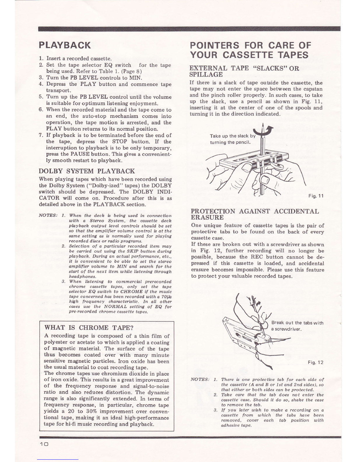
EXTERNAL TAPE "SLACKS'' OR
SPILLAGE
If there is a slack of tape outside the cassette, the
tape may not enter the space between the capstan
and the pinch roller properly. In such cases, to take
up the slack, use a pencil as shown in Fig. 11,
inserting it at the center of one of the spools and
turning it in the direction indicated.
Fis. 11
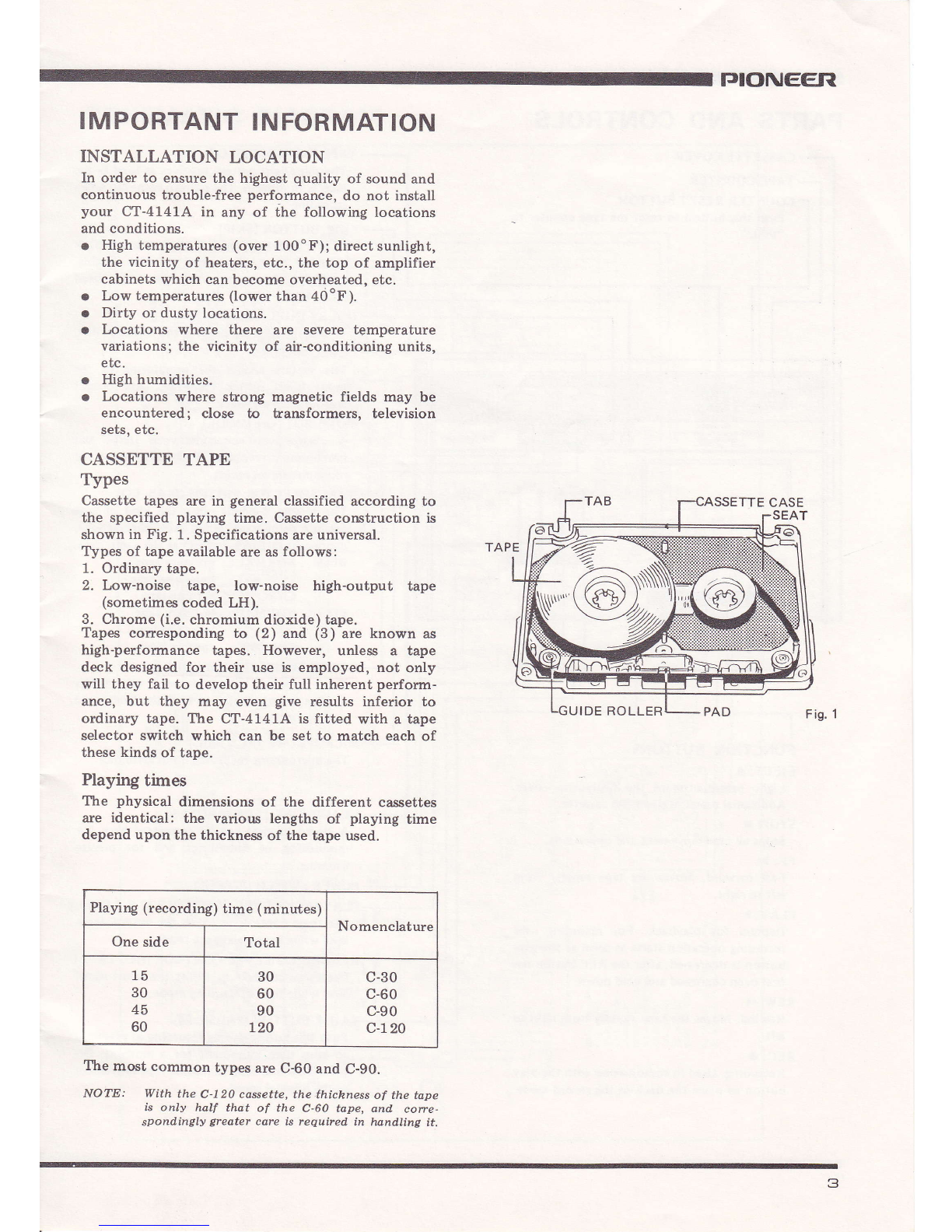
PROTECTION AGAINST ACCIDENTAL
ERASURE
One unique feature of cassette tapes is the pair of
protective tabs to be found on the back of every
cassette case.
If these are broken out with a screwdriver as shown
in Fig. 12, further recording will no longer be
possible, because the REC button cannot be de-
pressed if this cassette is loaded, and accidental
erasure becomes impossible. Please use this feature
to protect your valuable recorded tapes.
\? Break out the tabs with
a screwdriver.
Fig. 12
NO?ES: I. There is one ptotective tab for each sid,e of
the cassette (A and B or 7st and.2nd sid.es), so
that either or both sides can be protected,
'Idke care that the tab d,oes not enter the
cwsette case. Should it d,o so, shahe the case
to remoue the tab.
If you later wish to rnake a record.ing on a
cassette ftom which the tabs lnve been
remoued, couer each tab position with
adhesiue tape.
1.
2.
3.
4.
5.
6.
7.
I
o.
Take up the slack by
turning the pencil.
\\./
10
We wish to than k you for your
decision to purchase the Pioneer
Cassette Tape Deck CT-4'141A. Your
CT-4141A is a Cassette Tape Deck
equipped with a number of new func-
tions which enable you to derive the
maximum listening enloyment from
various types of cassette tapes ranging
from standard tape cassettes to Ihe
latest low-noise tape and high-perform-
ance chromium dioxide tape. Please
read this instruction booklet thorough-
ly before operating your new recorder
in order to obtain superb tone quality
recording and playback.
CONTENTS
Features of CT-4141A
Important information
Parts and controls
Connections diagram
Operational functions
Recording
Playback
Pointers for care of your
cassette tapes ...........
Pointers for long, trouble free
service from your deck ............
Trouble-shooting guide
Schematic Diagram
Use of the Dolby System .........
Operating principle of the
Dolby Svstem
Specifications ...........................
.)
J
4
5
6
8
10
10
11
t2
13
14
15
16
FEATURES OF CT.4141A
*
DOLBY SYSTEM
This top-quality deck has been specifically designed to incorporate Dolby
System recording and playback facilities. The Dolby System is effective in
reducing cassette tape "hiss" (mid- and high-frequency noise) during high
fidelity playback without in any way reducing sound quality.
NEWLY DEVELOPED PERMALLOY SOLID HEAD
We have succeeded in developing a new Permalloy Solid Top Head with over
ten times the abrasive resistance of conventional Permalloy Heads by making
full use of the Permalloy features and the development of a special alloy
technique, This new Permalloy Head in combination with a chromium
dioxide tape gives better response in the high frequency ranges, exhibits
excellent playback characteristics and overall superb performance. This
quality of sound reproduction is usually only found in open-reel tape decks.
TAPE SELECTION FOR ALL TAPES... INCLUDING
CHROMIUM DIOXIDE
You can use the latest chromium dioxide cassette tapes, with their great
improvement over conventional tapes in both frequency characteristics and
dynamic range, because the independent bias and equalizer circuits required
are available through the tape selector switch. When using chrome tapes the
playback equalizer operates at 70 gs, which gives an excellent S/N
(signal-to-noise ratio). The other position of the tape selector enables
conventional tapes to be used.
A WEALTH OF NEW AUXILIARY FUNCTION SUCH AS A
TAPE RUNNING PILOT LIGHT, SKIP BUTTON, etc.
Many new ideas are incorporated into the auxiliary devices to increase the
versatility and ease of operation of your new tape deck: the tape running
pilot light that provides at a glance an indication of tape transport in the
cassette; the skip button that makes it possible to accurately catch the
beginning of material while in the playback mode; and an easy-to-operate
pause button.
A FULLY AUTOMATIC STOP THAT GIVES
YOU WORRY.FREE OPERATION
Anyone can operate the deck without worry, since whether in the record,
playback, fast forward, or rewind modes, the automatic stop device
shuts off the tape deck when the end of the tape is reached.
EASY.TO.SEE SOUND LEVEL METERS
AND EASY.TO-USE CONTROL PANEL
Level Meters, a necessity while recording, are installed in both the left and
right channels. Also simple, easy-to-use slide-type level controls are incorpo-
rated. For your convenience, microphone jacks which can accept large-size
plugs, thus permitting the use of high-quality microphones, and the
headphone jack are installed on the same panel.
ELECTRONICALLY CONTROLLED DC MOTOR
ln order to achieve stable.tape transport under conditionsofvaryingsource
voltage and tape load, a DC motor controlled electronically by transistors
and diode is emploved.
*Manufactured under license from Dolby Laboratories lnc,
The word "Dolby" and [nare trade marks of Dolby Laboratories lnc.
2
IMPORTANT INFORMATION
INSTALLATION LOCATION
In order to ensure the highest quality of sound and
continuous trouble-free performance, do not install
your CT-4141A in any of the following locations
and conditions.
o High temperatures (over 100oF); direct sunlight,
the vicinity of heaters, etc., the top of amplifier
cabinets which can become overheated, etc.
o Low temperatures (lower than 40oF).
o Dirty or dusty locations.
o Locations where there are severe temperature
variations; the vicinity of air-conditioning units,
etc.
o High humidities.
o Locations where strong magnetic fields may be
encountered; close to fuansformers, television
sets, etc.
CASSETTE TAPE
Types
Cassette tapes are in general classified according to
the specified playing time. Cassette construction is
shown in Fig. 1. Specifications are universal.
Types of tape available are as follows:
1. Ordinary tape.
2. Low-noise tape, low-noise high-output tape
(sometimes coded LH).
3. Chrome (i.e. chromium dioxide) tape.
Tapes corresponding to (2) and (3) are known as
high-performance tapes. However, unless a tape
deck designed for their use is employed, not only
will they fail to develop their full inherent perform-
ance, but they may even give results inferior to
ordinary tape. The CT-4141A is fitted with a tape
selector switch which can be set to match each of
these kinds of tape.
Playing times
The physical dimensions of the different cassettes
are identical: the various lengths of playing time
depend upon the thickness of the tape used.
Playrng (recording) time (minutes) Nomenclature
One side Total
15
30
45
60
30
60
90
720
c-30
c-60
c-90
c-720
The most common types are C-60 and C-90.
NOTE: With the C-l20 casette, the.thichness of the tape
is only half that of the C-60 tape, and cone-
spond,ingly greater care h required in hand.ling it.
PIONEER
Fig. 1
TTE CASE
IDE ROLLER
3
PARTS AND CONTROLS
CASSETTE COVER
TAPE COUNTER
COUNTER RESET BUTTON
Push this button to reset the tape counter to
"000."
FUNCTION BUTTONS
EJECT: I
Light pressure opens the protective cover.
Add itional pressure eiects the cassette.
STOP: I
Stops all tape movement and operations.
FF: )>
Fast forward. Moves the tape rapidly from
left to right.
PLAY: >
Depress for playback. For recording: the
recording operation starts as soon as the play
button is depressed, after the REC button has
first been depressed and held down.
REW: <{
Rewind. Moves the tape rapidly from right to
left.
REC: O
Recording. Used in combination with the play
button to place the deck in the record mode.
TAPE RUNNING PILOT
The pilot-light pattern revolves as long as the
tape is in motion, The pattern turns red when
record ing.
sKrP BUTTON (SKrP)
lf this button is pushed while playing back
recorded tape, the sound remains audible,
while at the same time the tape speed
in creases.
DOLBY INDICATOR
The lamp lights by pushing the Dolby switch.
LEVEL METERS
The meters enable the monitoring of the
input levels during recording, and output
levels during playback.
MODE BUTTON (MODE)
A change-over switch between stereo and
monophonic recording. Push this button for
monophonic record ing.
TAPE SELECTOR SWITCH (BIAS, EQ)
The setting depends upon the kind of tape
cassette being used. When using chrome tape,
depress both BIAS and EQ at the same time.
BIAS ... NORMAL: ordinary tape
low noise tape
CHROME: chrome tape
EQ ..... NORMAL: ordinary tape
low noise tape
CHROME: chrome tape
DOLBY SWTTCH (DOLBY NR)
ffih the Dotby
System, or when playing back the Dolby-ized
tape record ings.
MTCROPHONE JAcK (Mtc)
The microphone recording input terminals.
HEADPHONE JACK (PHONES)
A stereo headset can be connected here, for
monitoring of record ings and for private
liste n ing.
POWER SWTTCH (POWER)
PLAYBACK LEVEL CONTROLS (p.8. LEVEL)
Use these controls to adiust the output signal
level while in the playback mode.
RECORDTNG LEVEL CONTROL (REC LEVEL)
Use these controls to adiust the input signal
level while in the recording mode.
PAUSE BUTTON (PAUSE: lf)
Push this button during recording or playback
to stop tape movement for a moment. De-
press a second time to resume tape movement
at the original speed.
4
CONNECTION DIAGRAM
cT-4141 A
STEREO AMPLIFIER
AC OUTLET
rJIONEER
Fis.2
rl
ll REC/PB c.onnection cord (optional)
ll use tnis cord instead of the
MON TAPE
Rec
R'GHt SPEAKER sysrEMs
IN CONNECTOR (REC/PB)
input and output con-Combines for both
nections.
LINE INPUT JACKS
Used for individual jack-plug input connec-
tions.
LINE OUTPUT JACKS
Used for individual lack-plug output con-
nections.
GROUND TERMINAL (GND)
This terminal should be grounded if externally
induced hum, etc., is obtrusive.
POWER CORD AND PLUG
5
OPERATIONAL FUNCTIONS
Please accustom yourself to the operation of your
CT-4141A cassette tape deck - the feel of the
operational buttons, and the functions of each part
- in the following order, checking that each is
functioning normally.
INSERTING AND REMOVING
CASSETTES
1. Gently depress the EJECT button, and the
protective cover will open.
2. Hold the cassette with the exposed tape side
towards you and push the cassette into the well.
It should snap audibly into place. Refer to Fig.
3.
3. Firmly depress the EJECT button, and check
that the protective lock is freed, the protective
cover is opened, and the cassette pops up so that
it can readily be removed,
TAPE TRANSPORT AND STOP
OPERATIONS
Operating in Playback Mode
1. Depress the POWER switch. The LEVEL
METER lamps will light, and the TAPE RUN-
NING PILOT light will come on (though it will
not rotate). At this stage the level controls (REC
and PB LEVEL) should be set to minimum.
2. Depress the EJECT button, and insert a cassette,
closing the cover afterwards. Check at this point
that the spool of tape is on the left hand side.
Refer to Fig. 4.
3. If the PLAY button is now depressed, the tape
will travel from left to right at the normal speed,
and the TAPE RUNNING PILOT will rotate to
the left (counterclockwise), and the TAPE
COUNTER will begin to function. This is the
state in which the playback of recorded tape is
normally performed.
4. Push the STOP button to stop tape transport.
This action automatically restores the PLAy
button to its "up" position, To restart tape
transport, merely depress the PLAY button
again.
Operating in Recording Mode
1. Operation is essentially the same as that for
playback.
2. When the PLAY button is depressed with the
REC button already down, tape transport from
left to right commences, the TAPE RUNNING
PILOT turns red (indicating that recording is
taking place), and the pattern begins to rotate to
the left.
PAUSE
1. Pushing the PAUSE button while in recording or
playback modes temporarily arrests the tape
transport. Neither the PLAY button (in PLAY-
BACK) nor the PLAY and REC buttons (in
RECORDING) will return to their previous
positions in this case, but will remain depressed.
2. Depressing the PATISE button a second time will
immediately restart tape transport.
3. The operation of the PAUSE button is only to
pull the pinch roller away from the capstan, and
interrupts nothing but the tape transport. It does
not stop the motion of the motor (or eapstan)
nor the operation of the amplifier.
SKIP BUTTON
1. Depressing the SKIP button while the tape is in
motion causes it to travel at about double the
normal speed. Please check this by noting that
the TAPE RUNNING PILOT rotates faster than
usual.
2. This button only remains operative as long as it is
depressed: it is non{ocking. Release it, and
immediately the normal speed is resumed.
NO?ES: 1. The SKIP button is uery conuenient, ailowing
you to ship ouer unuanted materials d,uring
pbybach or to edit the tape. Since the tape
speed. increases in playbach mode, you can
select your prefefted. spot while listeninq to
the soilnd.
2. In case you want to record, a different
ptogrum starting from the middle of the
recorded tape, utiJize the SKIP button. you
can easily find the spot uhile listening to the
sound..
3. The SKIP bulton b not operatiue in the
recording mod,e.
FAST FORWARD
1. Pushing the "FF" button causes the tape to
travel at high speed from left to right.
2. To stop the tape, depress the STOP button, and
the FF button will be unlocked and return to its
normal position as the tape stops.
The cassette with the tape
fully wound on the left side.
Fig. 3Fig.4
6
REWIND
1. Pushing the REW button causes the tape to travel
at high speed from right to left.
2. The fast REWIND operation is terminated by
depressing the STOP button.
AUTOMATIC STOP
When all the tape has been wound onto one side of
the cassette, whether in the record, playback, fast
forward, or rewind modes, the automatic stop
device ul'ill operate to stop tale transport and
release the respective buttons, even without depress-
ing the STOP button. The time taken for the auto-
stop device to function may varj/ slightly from deck
to deck, but will not exceed a few seconds.
TAPE COUNTER
When starting to record, push the reset button on
the right to "000." Then the beginning of the
material can be easily found during playback (Fig.
7).
IMPORTANT! PLEASE OBSERVE
1. While it is possible to switch directly from REW
to FF or vice versa with the tape in motion, this
is to be avoided, as it imposes undue strain on
the tape, or produces slack of tape "spillage." Be
sure to first press the STOP button before
changing to the next operation.
2. Do not depress the EJECI button while the tape
is in motion. Always be sure to depress the STOP
button first to arrest the tape transport, before
pushing the EJECT button.
PIONEEII
Fis. 6
Fig.7
*:'
L---l I I
rl
PUSH
Stereo and Mono Tapes
Fig. 8 shows the hacks used in recording
tapes. Each track is fed to a different channel of
amplifier used in playback. The CT-4141A is
four-track two<hannel stereo cassette tape deck. A
is clear from the figure, when recording side A (
first side), traeks L1 and R1 are used, and for side
(the second side), tracks L2 and R2. With
tapes which have been reeorded monophonicall
(mono), the two sets of stereo tracks are each
combined to a single track, (L + R) and (L + R
respectively. Such cassettes ean be played on
stereo deck, and the reverse is also true, for
recordings can be played on a monophonic deck.
TAPE RUNNING:
SIDE BSTEREO
MONO
2L2
R,
R1
LI
TAPE RUNNING:
SIDE AFig. 8
Fig. 5-B
RECORDI NG
RECORDING FROM RECORDS AND
BROADCASTS
(LINE INPUT or REC/PB connectors)
1. First insert the cassette you intend to record. Be
sure to set the TAPE SELECTOR switch for the
type of tape you are using (both BIAS and Ee
selection). Please refer to Table 1.
NORMAL (do not depress button): Ordinary
tape and low noise-tape.
CHROME (depress the button): Chrome tape
2. Set the REC LEVEL (recording level control) to
MIN.
3. For stereo recording, switch MODE button to
STEREO: for monophonic recording, push the
button to MONO.
4. Press both the REC and PLAy buttons at the
same time. The TAPE RTINNING pILOT will
turn red and the tape transport.will commence.
Please refer to Fig. 9.
5. After the tape has been moving for some B to b
seconds, press the PAUSE button, and stop the
tape.
6. Use the REC LEVEL controls to set the input
level.
7. Press the COUNTER RESET button, setting the
TAPE COUNTER to "000." This completes the
preparations for recording.
Press the PAUSE button a second time and
release it, and you can commence recording the
program source of your choice.
To arrest tape transport temporarily, use the
PAUSE button; when you have finished record-
ing, depress the STOP button.
NOTE: The sigrcl to be recorded, can be monitored. with
the PAUSE button depressed.. The sound signal
can be heatd both uia stereo head.phones or the
stereo sy stem speahers.
TAPE SELECTOR SETTINGS FOR
VARIOUS MANUFACTURERS' TAPES
Table 1.
NOTE: When using chrome tapes, set both BIAS and Ee
switches at the same time. For other tapes, there
will be some tdpes which will perform better with
a different suitch setting.
8.
9.
Start recording by pushing the
REC and PLAY buttons.
Push the PAUSE button
for momentary stopping.
BrAS, EQ
switching TAPE
NORMAL
POSITION
MEMOREX c-60, c-90
SONY c-60, c-90
c-60HF, C-90HF
BASF c-60LH, C-90LH
FUJI FM C-60, FM C-90
FL C-60, FL C-90
TDK D C-60, D C-90
sD c-60, sD c-90
ED C-60. ED C-90
scoTcH c-60, c-90
(DYNARANGE)
MAXELL c-60, c-90 (LN
(LN series)
c-60, c-90
(UD series)
AGFA c-60, c-90
SUPER C.6O+6
SUPER C-90+6
CHROME
POSITION
MEMOREX CHROMIUM
DIOXIDE C.6O
CHROMIUM
DIOXIDE C-90
SONY c-60cR, c-9OcR
BASF CHROMDIOXID C-60
CHROMDIOXID C-90
FUJI FC C-60, FC C-90
MAXELL CHROME DIOXIDE
c-60 (cR)
CHROME DIOXIDE
c-eo (cR)
TDK KR C.60, KR C-90
RECORD
BIAS _
NORMAL
EQ
CHROME
PLAY BACK
EQ
CHROME
SONY DUAD C-60
DUAD C-90
Fis.9
a
PIONEETI
RECORDING BY MICROPHONE
For Stereo Recording
1. Insert a stereo microphone or two regular micro-
phones into the microphone jacks. When doing
this, do not confuse the relationship between the
left and right positions of the microphone plug
and the jack. Please refer to Fig. 10.
2. The rest of the operations follows the same
principle as that of "Recording from Records
and Broadcasts."
For Monophonic Recording
1. Set the tape and push the MODE button.
2. Insert the microphone into the microphone jack.
You can record by using either left or right
microphone.
3. The rest of the operations follows the same
principle as that of "Recordings from Records
and Broadcasts."
NO?ESi 1. With the MODE suitch turned, to MONO, one
microphone embles the simultaneous record,-
ing in both left and right tracks: with the
STEREO mode, recording in either left or
right trach becomes possible.
2. When not recording through the microphone,
be sure to pull out the microphone plug. If it
is left unplugged, the signal from nEC/pB
terminal or LINE INPUT cannot be record,ed,.
3. Proper microphones (for the we of Mono-
phonic Recording) are d,ynamic-type and
electret-tlpe. In terms of impedance, a high-
impedance type is better suited,. Do not usea
microphone cord extend,ing ouer 16.5 ft.
Lou-impedance (60)db microphone cord,
extending ouer 16.5 ft. is usable, but the use
of o matching booster transformer is suggest-
ed.
DOLBY SYSTEM RECORDING
Depress the DOLBY switch, and check that the
Dolby indicator lamp comes on. Once this has been
done, proceed with recording as detailed in the
previorx sections. Please also refer to page 14, ..1hs
Use of the Dolby System. "
ERASING
Previously recorded material is automatically erased
before subsequent recordings made with the same
cassette. If it is desired to erase the previous
material without recording any new material, set the
deck to the "record" mode, move the REC LEVEL
controls to MIN and run the tape in the normal
way.
LEVEL METERS
Your level meters are, in fact, a kind of voltmeter.
They have twin calibrations, dB above the line
(figures in black for negative values and in red for
positive) and percentages (with) dB corresponding
to 70OVo below the line. The dB units are also
termed "Volume Units" (LEVEL), and these meters
give the same kind of indication as used for
monitoring purposes in the VU meters in radio
broadcasting stations, etc.
LEVEL SETTING
The magnitude of record input level is a very
important factor in making high quality hi-fi record-
ings. Use the REC LEVEL controls to make the
settings. The best results are obtained when the
above-the{ine meter indication does not exceed a
normal average of -3dB. Distortion will occur if the
needles remain pegged at full scale while recording is
taking place. Optimum pointer deflection will
depend upon the nature of the program sources, and
can vary very widely. The following is a general
guide to suitable levels, but fine adjustment will be
necessary,
1. Announcer's voice -10 to -5dB
2. Loud (forte) music
passages +1dB
3. Soft (piano) music
passages -15d8
4. Average musical sound -10 to -SdB
I