Tandem USLED User manual

CABINET LIGHTING
RETROFIT INSTALLATION GUIDE
UNIQUE
LIGHTING
SOLUTIONS

RETROFIT INSTALLATION GUIDE
Page 2
US LED | 6807 PORTWEST DR | HOUSTON, TX 77024 | T 866 972 9191 | F 713 972 9393 | [email protected] | www.usled.com
Updated 05.19.11
The retrot installation must only be performed by a licensed electrician.
To prevent death, injury or damage to property this product must be installed in accordance to National Electric
Code in the US or Canadian Electrical Code (CSA22.1) in Canada.
Disconnect power before installing the product or servicing it.
Wait until the lamp(s) have cooled down before retrotting or servicing the xture.
The retrot kit is to be installed only in UL Listed signs.
US LED Channel Letter modules are only to be used with the 24VDC power supplies listed in this guide.
WARNING
l
l
l
l
l
l

RETROFIT INSTALLATION GUIDE
Page 3
US LED | 6807 PORTWEST DR | HOUSTON, TX 77024 | T 866 972 9191 | F 713 972 9393 | [email protected] | www.usled.com
Updated 05.19.11
RETROFIT COMPONENTS
Tandem 4-foot unit (Figure 1)
G1-14-24-4W: Single Sided, 4-foot Tandem unit
G2-14-24-4W: Double Sided, 4-foot Tandem unit
Tandem Rail Clip (Figure 2)
Tandem Mounting Brackets (Figure 3)
Quick Connect Jumper Wires (Figure 4):
RLSW-12: Pair of 12” Quick Connect Jumper Wires
RLSW-24: Pair of 24” Quick Connect Jumper Wires
RLSW-36: Pair of 36” Quick Connect Jumper Wires
Class 2 Power Supply, 24VDC (Figure 5):
PSA-24-80: Advance model number LED120A0024V33F, 24VDC, 80W power supply
PSA-24-100: Advance model number LEDINTA0024V41FO, 24VDC, 100W power supply
#8 self drilling screws (Figure 6)
Wire nuts (Figure 7)
REQUIRED TOOLS
Drill
.125” (1/8”) drill bit
.250” (1/4”) nut driver
Saw for cutting aluminum
Wire cutter
Figure 5: Power Supply
Figure 6: Screws Figure 7: Wire Nuts
Figure 4: Quick Connect Jumper WiresFigure 3: Mounting BracketFigure 2: Rail Clip
Figure 1: Tandem 4-foot unit
Module Jumper Tab Wire Cover

RETROFIT INSTALLATION GUIDE
Page 4
US LED | 6807 PORTWEST DR | HOUSTON, TX 77024 | T 866 972 9191 | F 713 972 9393 | [email protected] | www.usled.com
Updated 05.19.11
Tandem units are:
1. 48” long with modules equally spaced every 6”.
2. Designed to be mounted 6” back from the sign face equally spaced up to 12” apart.
3. Designed to operate at 24VDC, constant voltage.
4. Designed to be cut in multiple lengths of 6”:
a. Cut wires midway between modules.
b. Cut extrusion 90 degrees to the unit length using any saw designed to cut aluminum. Do not cut through
module. If desired length is behind a module, loosen the screw and slide the module to clear the cut line.
5. Designed to be stacked end-to-end:
a. Slide rail clip into center slot of two Tandem units.
b. Push or tap units together until the two extrusions contact each other
c. Secure rail clip to each extrusion using a self drilling screw approximately ½” from the joint.
d. Join like colored wires.
e. Repeat for each joint.
TANDEM OVERVIEW

RETROFIT INSTALLATION GUIDE
Page 5
US LED | 6807 PORTWEST DR | HOUSTON, TX 77024 | T 866 972 9191 | F 713 972 9393 | [email protected] | www.usled.com
Updated 05.19.11
1. Disable power.
2. Open cabinet sign face.
3. Disconnect source and remove all ballasts.
4. Remove all uorescent lamps. Note the length of the uorescent lamp to determine the length of the Tandem unit.
5. Determine the quantity of Tandem units needed to ll the sign face. For power supply loading, see the table on
Page 6 or follow this link: www.usled.com/cabinet_sign_loading.htm.
6. Attach mounting brackets to the wire raceways using self drilling screws. Position brackets so module face is
6” back from the sign face and the Tandem units are symmetrically spaced between 9” to 12” apart along the
top for vertical applications, or the left side for horizontal applications. If mounting bracket interferes with uo-
rescent socket, slightly offset bracket to clear the socket (Figure 10).
7. Place Tandem unit in sign by rst inserting a mounting bracket into the middle slot (Figure 11), then place the
middle slot of the opposite end of the Tandem unit onto one of the mounting brackets attached in step 6. Se-
cure to mounting bracket using self drilling screw positioned approximately ½” from the end. If screw is drilled
through the xture, be sure to seal the screw hole to prevent water intrusion.
INSTALLATION INSTRUCTIONS
Figure 8: Cutting Tandem units Figure 9: Joining Tandem units
Figure 10: Offsetting bracket from socket
Figure 11: Inserting mounting bracket

RETROFIT INSTALLATION GUIDE
Page 6
US LED | 6807 PORTWEST DR | HOUSTON, TX 77024 | T 866 972 9191 | F 713 972 9393 | [email protected] | www.usled.com
Updated 05.19.11
G1-14-24-4W
G2-14-24-4W
Model Number
Power Supply Loading
4
2
27
13
Feet / 80W
Min Max
4
2
27
13
Feet / 100W
Min Max
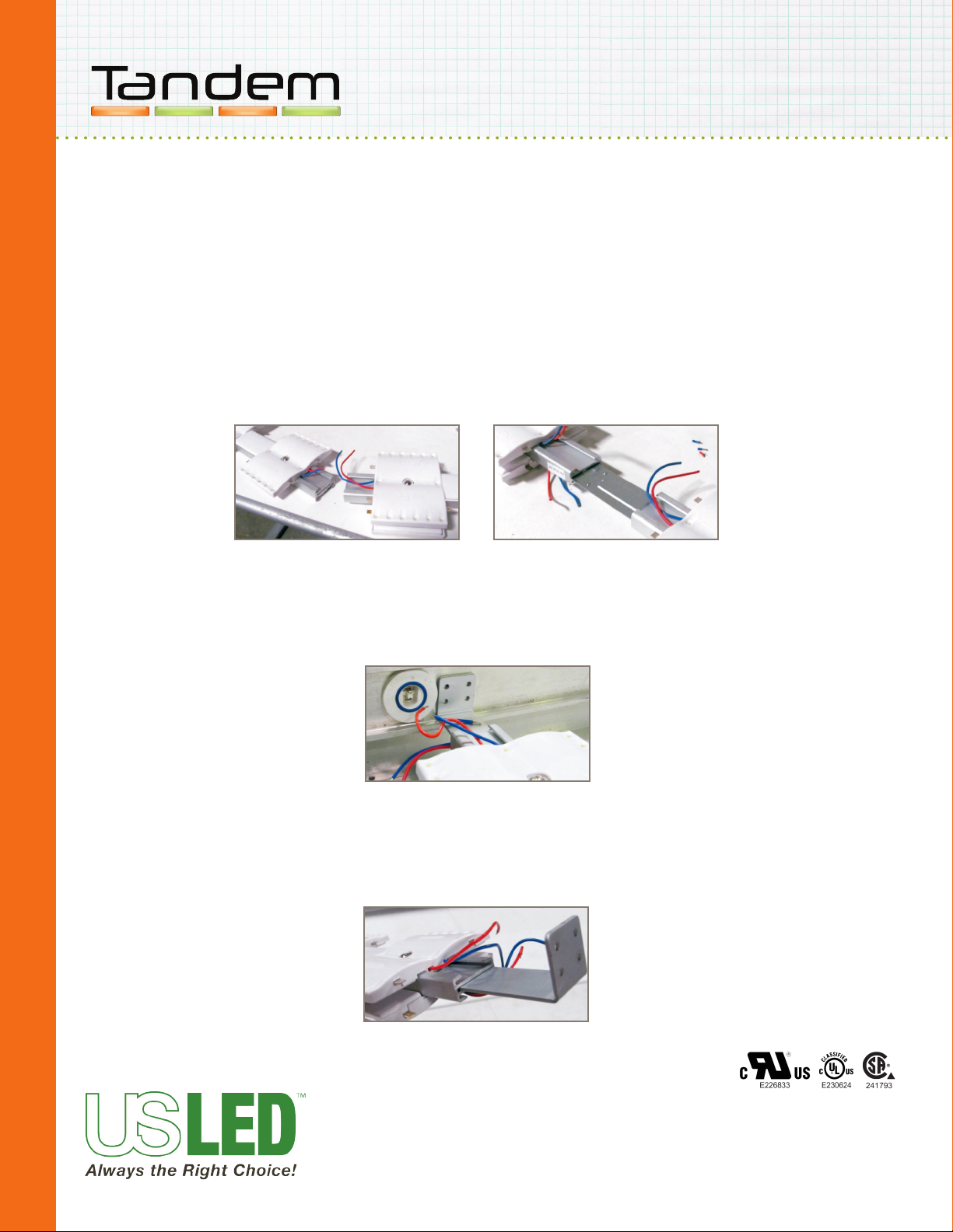
8. Secure the loose mounting bracket to the wire raceway using a self drilling screw (Figure 12).
9. Secure Tandem unit to mounting bracket using self drilling screw positioned approximately ½” from the end.
10. Repeat steps 7, 8 and 9 for the remaining Tandem units.
11. Install and connect power supplies to source in accordance with National Electrical Codes and any applicable
local codes.
12. Refer to US LED data sheet for proper power supply loading.
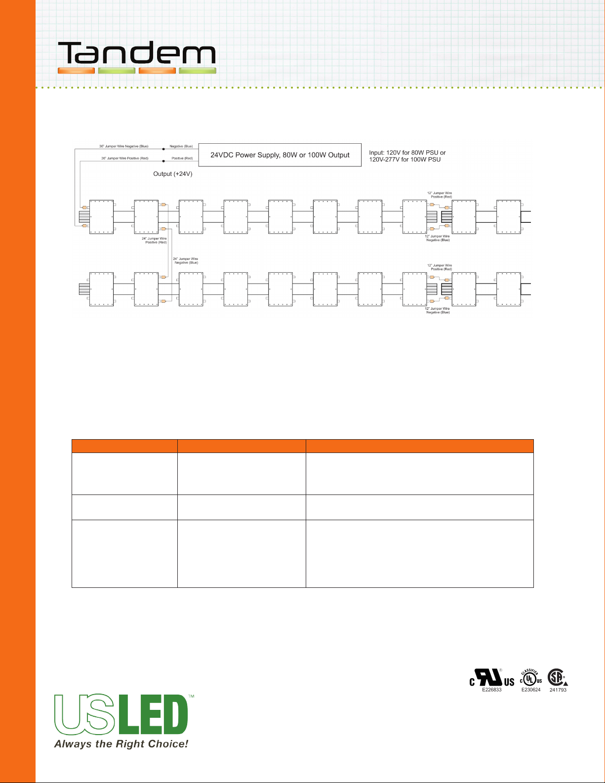
13. Use 36” Quick Connect Jumper Wires between Power Supply and Tandem unit module tabs (minimum 1
18AWG wire with 1 20AWG; maximum 4 16AWG with 1 20 AWG). Red wire to the positive “+” tab, Blue wire to
the negative “-” tab of the Tandem module. See Wiring Diagram on Page 7.
14. Use 6” Quick Connect Jumper Wires to energize Tandem units within the same row/column. Red wire to the
positive “+” tabs, Blue wire to the negative “-” tabs of the Tandem modules. See Wiring Diagram on Page 7.
15. Use 24” Quick Connect Jumper Wires to energize adjacent row/column of Tandem units. Red wire to the posi-
tive “+” tabs, Blue wire to the negative “-” tabs of the Tandem modules. See Wiring Diagram on Page 7.
16. Cut wires between modules to achieve the desired amount of modules per power supply (per loading chart).
Place wire nut over cut end of wire.
17. Repeat steps 11 through 16 until system is completed.
18. Attach cabinet sign face.
19. Energize xture.
INSTALLATION INSTRUCTIONS (cont)
Figure 12: Securing mounting bracket

RETROFIT INSTALLATION GUIDE
Page 7
US LED | 6807 PORTWEST DR | HOUSTON, TX 77024 | T 866 972 9191 | F 713 972 9393 | [email protected] | www.usled.com
Updated 05.19.11
WIRING DIAGRAM
TROUBLESHOOTING
A single module not lighting
Symptom Possible Cause Solution
LEDs icker
Entire product run is not lighting
Malfunction on module
A. Underloaded or overloaded
B. Malfunctioning power source
A. Bad wire connections
B. If only one run of product on power
source, malfunctioning power source
C. Short
D. Overload
Replace bad module by cutting the blue and red wires on both ends of
the bad module. Detach bad module from the aluminum extrusion and
replace with a new functioning module. Use wire nuts to splice wires
on both ends of the new module to the adjacent modules.
A. Adjust loads on power sources to be within recommended limits.
B. Replace power source.
A. Restore connection.
B. Check power source and replace if appropriate.
C. Search wiring for a short circuit between the red and blue wires.
Replace bad wiring or use electrical tape to insulate the bad wire(s).
D. Adjust loads on power sources to be within recommended limits.
Table of contents