Tandy 26-2814 User manual

HOWARD W. SAMS &COMPANY
COMPUTERFACTS
Technical Service Data
TANDY®
MODEL DMP132(26-2814)
PRINTER
FEATURES COMPLETE SCHEMATICS •PRELIMINARY SERVICE CHECKS •TROUBLESHOOTING TIPS
EASY-READ WAVEFORMS •REPLACEMENT PARTS LISTS •SEMICONDUCTOR CROSS-REFERENCE

§AM§ COMPUTEREACTS' TANDY
MODEL DMP1 32(26-281 4)
PRELIMINARY SERVICE CHECKS
v;
§5
za
<^
o
This data provides the user with atime-saving
service too! which Is designed for quick isola-
tion and repair of Computer system malfunc-
tions.
Check all interconnecting cables for good
connection and correct hook-up before making
service checks.
Always turn printer Off before connecting or
disconnecting connectors, boards or Computer.
TEST EQUIPMENT AND TOOLS
TEST EQUIPMENT
Digital Vo it/Ohm Meter
TOOLS
Head Cleaning Equipment (Ethyl Alcohol)
Contact and Switch Cleaner (non-spray type)
Phillips Screwdriver
F!at-3iade Screwdriver
iC insertion and Removal Tools 28 pin
Low Wattage Soldering Iron
Desolderlng Equipment
SAMStm 4300 West 62nd Street, P.O. Box 7092, Indianapolis, Indiana 46206 U.S.A.
The listing of any available replacement part herein does not
constitute in any case arecommendation, warranty or guaranty
by Howard W. Sams &Co. as to the quality and suitability of
such replacement part. The numbers of these parts have been
compiled from information furnished to Howard W. Sams &Co.
by the manufacturers of the particular type of replacement part
!sted 89CP19094 DATE 10-83
Reproduction or use, without express permission, of editorial or pic-
torial content, in any manner, is prohibited. No patent liability is
assumed with respect to the use of the information contained herein.
©1989 Howard W. Sams &Co.
4300 West 62nd Street, P.O. Box 7092, Indianapolis, Indiana 46206
U.S.A. Printed in U.S. of America

TO FRONT
CONTROL
PANEL
CN4
CN3
D2
1
CN5
\
CN1
TO HOME
POSITION
SWITCH
MAIN LOGIC BOARD
PRELIMINARY SERVICE CHECKS (Continued)
161 1CN2
U
13
(2E) (3E) CN7 CN6
TO PAPER
SET
SWITCH
4D)(5C) 12 13
12V.
-12V.
24V-
CN12
5V/ 1
CN11 CN10
814
TO PRINT HEAD
CN9 CN8
H
31
TO LINE ^
FEED MOTOR T0 CARRIAGE
MOTOR
/
TO PAPER
EMPTY
SWITCH
-12V B
24V X-, E©
-76°) r® °Q101
/J>^ AD203
~Z /D201
—H#- COMMON
~* \*y POINT
J22°3D202i
©B(1C
Q102
POWER SUPPLY
-,, ON/OFF
<? POWER
SWITCH
o
TO CN9
CN9-5 BLINEFEED
GEAR ASSEMBLY
CN9-
CN9-4
UNEFEED MOTOR
/TO CN8
TO CN3
AND CN4
TO CN6
/
PAPER
EMPTY
SWITCH
TO CN7 1
V
PAPER
SET
SWITCH
PLATEN
TO CN10 AND CN11 GUIDE plLLAR
SCREW
POWER D
ALERT D®
D
Cw
FRONT Vr
PANEL
LEVER OF AUXILLARY BOARD
SCREW
TO ADJUST GAP
HOLD ONLY THIS
PART WITH PLIERS
HEAD ADJUSTMENT LEVER
GUIDE PILLAR
CN8-4
CN8-6
CARRIAGE MOTOR
(3D)
ON/OFF
LINE
•sV NLQ/DP
FORM
FEED
UNE
FEED
m
o
o
m
r-
D_i
s>
2z
"2
IO <
0)
to
00
INTERCONNECTING DIAGRAM
II
INTERCONNECTING DIAGRAM
m

PRELIMINARY SERVICE CHECKS (Continued)
tltitiiiiifiiiiiii
MAIN LOGIC BOARD
0©0
©
MAIN LOGIC BOARD
X
MAIN LOGIC BOARD
III

PRELIMINARY SERVICE CHECKS (Continued)
GENERAL OPERATING INSTRUCTIONS
POWER LIGHT
The Power Light comes On when the printer Is
properly connected to 120VAC power and the
POWER ON/OFF switch Is sat On*
ALERT LIGHT
The Alert light will come on when the printer
Is out of paper9The Alert light blinks when
there Is ahardware fault.
ON/OFF LINE LIGHT
The light will be On when the printer Is On
line and ready. ON/OFF light will blink In
the Pitch-set Mode.
NLQ LIGHT
The NLQ Sight will be
printer Is In NLQ Mode.
ON/OFF LINE SWITCH
turned On when the
At Power Up .the printer Is On Line and ready
to print. When the switch Is pressed once
printer will go Off Line,, Press and hold this
switch for amoment while In On Line Mode to
enter the Pitch-set Mods,,
NLQ/DP SWITCH
This switch selects either NLQ or standard
print mode. In the Pitch-set Mode, pressing
this switch sets the pitch.
FORM FEED SWITCH
This switch will advance the paper 'to the next
top-of-form position. This switch works only
when the printer Is Off Line. In the
Pitch-set Mods, pressing this switch moves the
Print Head to the left.
LINE FEED SWITCH
This switch will advance the paper one line.
For continuous paper feed press and hold this
switch. In the Pitch-set Mode, pressing this
switch moves the Print Head to the right.
CHARACTER PITCH SET SWITCHES
Character Pitch can be set by either of two
methods
;
1. Front Panel Method. In this case any
control cods from the computer will have no
effect on the printing. To select the
character pitch using the front panel, set the
printer In On Line Mode. Press and hold the
pitch (ON/OFF Line) switch until the 0?^ Llns
Indicator blinks. Press the (LINE FEED) or
(FORM FEED) switch to move the print head
to the position Indicated on the print cover,
Pica 10, Elite 12, Condensed 17, MIcrofont 17
or Proportional, to select acharacter pitch.
Press the SET (NLQ/DP) switch to set the
selected character pltcho
DIP SWITCH FUNCTIONS
NOTEs The printer must be powered Off before
changing Dip Switch settings.
DIP SWITCH 1
SW 1-1 CONTROL CODES
SW 1-1 Is set OFF for the printer to select
TANDY Mode.
SW 1-2 Is set ON for the printer to select
IBM Mode.
SW 1-2 CARRIAGE RETURN
SW 1-2 tf set ON, carriage return only on
carriage return,,
SW 1-2 If set OFF, carriage return and line
feed on carriage return.
SW 1-3 LINE FEED
SW 1-3 if set ON, line feed will be with
every carriage return.
SW 1-3 If 'set OFF, line feed will be per-
formed without carriage return.
SW 1-4 FORM LENGTH
W1-4 Is set ON for form length of 12
Inches.
if OFF for for
SW 1-5 PERFORATION
SH 1-4 Is
Inches, length of 11
SH 1-5 1Inch skip perforation.
SW 1-5 Is set On for valid perforation.
SW 1-3 Is set OFF "for not valid
perforations
SW 1-6 LINE SPACING
SW 1~6 If set On Line Spacing wll .;,? :/:.
SW 1-6 If set OFF Line Spacing will be 1/6
Inch
SW 1-7 CHARACTER SET
If SW 1-1 Is OFF, SW 1-7 will select
between IBM and TANDY characters. If SW1-7
Is ON IBM character set Is selected. If SW
1-7 Is OFF TANDY character set Is selected.
If SW 1-1 Is ON, SW 1-7 will select between
IBM character set 1and 2. IF SW 1-7 Is ON
IBM character set 2Is selected. if SH 1-7
Is OFF IBM character set 1Is selected.
W

SW 1-8 IN TANDY MODE
PRELIMINARY SERVICE CHECKS (Continued)
GENERAL OPERATING INSTRUCTIONS (Goniiiiyeel)
WP/DP MODE
1-8
sleeted.
if SW 1-8
selected.
!s On Word Processing Mode Is
fs Off Data Processing Mode Is
wl I
SW 1-8 In IBM Mode Buffer Full
If SW 1-8 Is ON the printer
carriage return only.
If SW1-8 Is OFF the printer
carriage return and line feed.
DIP SWITCH 2
SW 2-1 and SW 2-2 select the Interface
baud rate for serial Interface.
will do
cz
and
PARALLEL
SW2-1 OFF
SW2-2 OFF
Serial
600bd
OFF
Serial
1200bd
...
OFF
feria:
2400bd
INSTALLING THE PAPER RACK
To Install the paper rack on the printer, open
the printer cover. Hold the paper rack
upright, Insert the tips of the rack on the
supporters on both sides of the printer on top
cover. For single sheet printing pull up the
folding leg and Insert ft Into the hole
centered on top the case. For printing on con-
tinuous fanfold paper place the rack In Its
horizontal position.
INSTALLING TRACTOR FEED UNJT
To Install the tractor feed, turn the printers
power switch OFF, remove the paper rack and
open the printer coyer.Place the front pins
Into the holes then push down on the rear of
the tractor unit until the tractor Is secured
In position. Turn the platen knob clockwise
to move the paper ball toward the platen.
SEMSORS AND DETECTORS OPERATION
Home Position Sensor. When the carriage
assembly pushes against the Mlcroswltch of the
Home Sensor the mfcroswltch Is turned on
causing pin 35 of the CPU IC CP9) to go low,
PAPER EMPTY DETECTOR
The Paper Empty Detector Is aphoto sensor
activated by the reflections of light produce
by the LED In that sensor. When paper
reflects the light the sensor transistor i
turn On and pin 34 of the CPU IC (P9) wit iH
check logic h?gh. If the printer runs out off
paper the sensor transistor will be turned OFF
and pin 34 of the CPU IC P9 will check logic
low*
AUTOMATIC PAPER LOADING SWITCH
The automatic paper Loading Switch Is amSero-
sa Itch which can be turn On by turning the
Paper Loading Knob counterclockwise. When the
mlcroswltch Is turned on pin 36 of the CPU IC
P9 checks low.
0000 ©00
ZO203 ?m -12V POWER SUPPLY QIS\ ..no;- it, «
-,
"'' ':"
00
M
*m
m
:,ip
POWER SUPPLY BOARD

PRELIMINARY SERVICE CHECKS (Continued)
SELF-TEST
To run self-test, press and hold the LINE FEED
switch while turning the powsr switch on. The
printer will print the self-test In standard
font. If the NLQ switch is pressed Instead of
the LINE FEED switch, the test will be printed
In the Quality font.
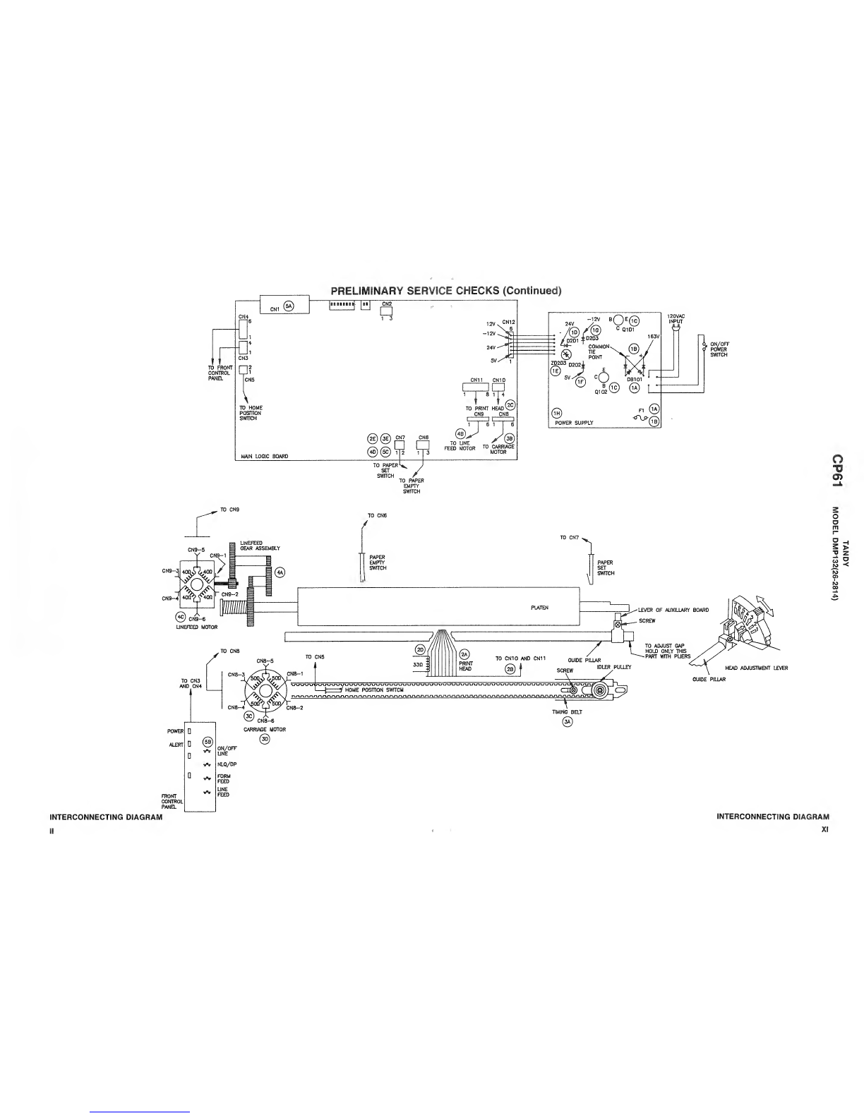
PRINT HEAD PLATEN GAP ADJUSTMENT
MISCELLANEOUS ADJUSTMENTS
holding the auxiliary board. Push the lever
towards the platen slightly while holding the
guide pillar (front shaft of the carriage
assent Iy). Tighten the screw then run the
self-test again and check the print quality.
On the right hand side of the platen Is the
Print Head adjustment lever. This lever
allows adjustment of the Print Head according
to paper thickness variations. When the gap
Is too narrow It can cause smudging In the
printout, paper damage at the left or the
right margin, or Inaccurate line feedSrig„ If
the gap Is too wide It can cause light
printing or missing characters. When the Head
adjustment lever Is pushed all the way towards
the platen it Is set to position (1). When
the lever Is pulled away from the platers it Is
set to position (7).
Perform the self-test printing In standard
character mode, when the Head adjustment lever
Is at positions (2), (3) and (4). If smudging
appears at position (2), loosen the screw
If printing Is light or missing some
characters at position (4) loosen the screw
holding the auxiliary board. Pull the lever
slightly towards the front of the printer
while holding the guide pillar. Tighten the
screw. Run the self-test and check the print
quality. The adjustment Is complete when the
print quality Is satisfactory.
TIMING BELT TENSION ADJUSTMENT
The tension of the timing belt can be adjusted
by moving the position of the Idler pulley. on
the right hand side of the timing belt.
Loosen the screw, then press the Idler pully
outward to put tension on the timing belt,
tighten the screw to hold the Idler pulley
plate block In place. Check the widths of
printed characters at the first and second
columns. If the widths of characters are
improper it Is required to readjust the
tension of the timing belt.
TOP CABINET REMOVAL
DISASSEMBLY INSTRUCTIONS
PRINTER MECHANISM REMOVAL
Open and remove the printer cover. Remove the
paper rack if Installed® Remove two screws
from the front and three screws from the back
of the printer. Carefully lift up the top
cabinet and unplug connectors CN2, C83 and
CN4. To unplug the connectors push down the
connector, then pull the leads out of the
connector. Remove the Top Cabinet frosn the
Printer.
FRONT PANEL REMOVAL
Remove the Top Cabinet, then press four tabs
and remove the Front Panel from the Top Cabi-
net.
MAIN LOGIC BOARD REMOVAL
Remove the Top Cabinet. Remove four screws
fastening the Main Logic Board to the Bottom
Cabinet. Disconnect connectors CN5 thru CM12.
Lift the Main Logic Board out of the Bottosr,
Cabinet.
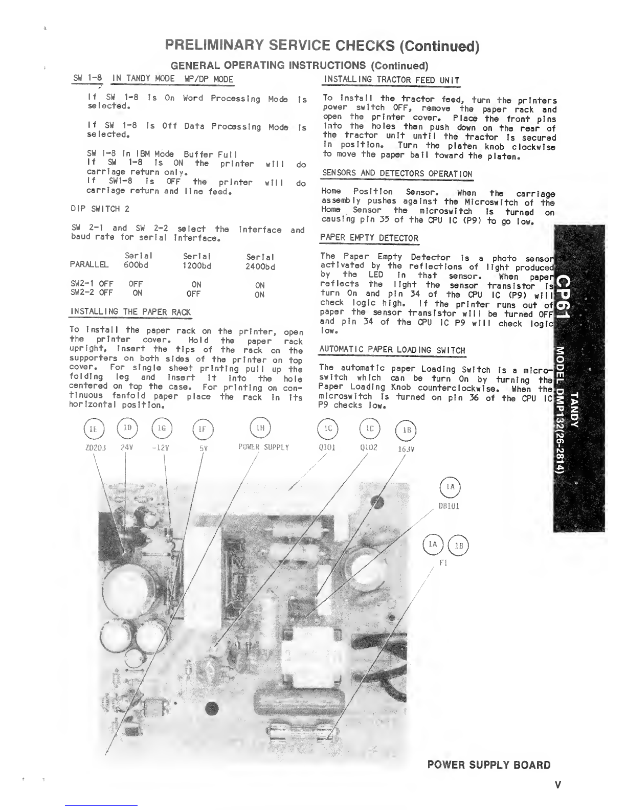
POWER SUPPLY BOARD REMOVAL
Remove the Top Cabinet. Remove two screws
holding the Power Supply board. Slide On/Off
switch up out of Its slot in the cabinet
bottom. Disconnect connector CN12. Lift the
Power Supply Board out of the cabinet.
Remove the Top Cabinet. Remove four screws
holding the Printer Mechanism to the cabinet
bottom. Disconnect connectors CN5 thru CN1 1
from Main Logic Board. Lift the mechanism out
of the printer cabinet bottom.
CARRIAGE MOTOR REMOVAL
Remove the Top Cabinet. Remove two screws
holding the carriage motor. Slide the
carriage motor to the left and disconnect
connector CN8. Remove the carriage motor from
the mechanism.
LINE FEED MOTOR REMOVAL
Remove the tractor, lift it from the rear and
pull It upward. Remove three screws which
hold the line feed gear box. Carefully slide
the line feed motor upward to remove it. Dis-
connect the line feed connector CN9 from the
logic board. Remove the line feed motor from
the printer.
PRINT HEAD REMOVAL
Remove the metal plate FBC guide securing the
print head, using aflat screw driver. Dis-
connect the flexible cable of the print head.
PtilS the print head toward the front to remove
:- -
y?

PRELIMINARY SERVICE CHECKS (Continued)
SERVICE CHECKS
MATCH THE NUMBERS ON THE INTERCONNECTING DIAGRAM AND PHOTOS WITH
THE NUMBERS ON THE SERVICE CHECKS TO BE PERFORMED.
POWER SUPPLY CARRIAGE ASSEMBLY DOES NOT MOVE.
(A) Check AC Fuse (F1), if open, check
Bridge Rectifier (DB101) for ashort.
(B) Replace AC Fuse (F1) and power On.
Check for 163V at the cathode of
Bridge Rectifier (DB101), measured
from common tie point.
(C) Check transistors 0101 and Q102 for
shorts.
(D) Check for 24V at the cathode of Diode
D201.
(E) If the 24V Is missing check Zener
Diode (ZD203) for short.
(F) Check for 5V at the cathode of Diode
D202.
(G) Check for -12V at the anode of Diode
D203.
(H) if any of the voltages are missing
check the Power Supply Board by sub-
stitution.
(A)- Turn OFF the printer and manually move
the carriage assembly back and forth
to check for binding. Check the
timing belt and the gear assembly on
the left side.
(B) Check carriage motor connector CN8 for
good connection.
(C) Check the carriage motor windings
resistances. Check for 50 ohms for
each winding.
(D) Check the carriage motor by substi-
tution.
(E) Check the Main Logic Board by substi-
tution.
o
LINE FEED WILL NOT OPERATE
PRINT HEAD WILL NOT PRINT
(A) Check Print Head face for contamina-
tion.
(B) Check Print Head Cable for good con-
nection.
(C) Check connectors CN10 and CN11 for
good connection on the Main Logic
Board.
(D) Check resistances of Print Head
Solenoids, check for 33 ohms for each
solenoid.
(E) Check Main Logic Board by substitu-
tion.
(A) Turn OFF the printer and manually
turn the platen knob. Check for any
binding and check the Line Feed gear
Assemb ly.
(B) Check the resistance of each winding
on the Line Feed Motor. Check for 40
ohms for each winding.
(D) Check Main Logic Board by substitu-
tion.
",;
;.;
-
>
'2
TJ
«
yv:
a
PRINTER WILL NOT ACCEPT DATA
CN1 and(A) Check connector
cable. Interface
(B) Check ON/OFF line switch by pressing
S+ once. The ready light should come
ON. Pressing It again should turn
light OFF.
(C) Check Main Logic Board
tlon. by substltu-
VS[

PRELIMINARY SERVICE CHECKS (Continued)
::
v...-;•-
:".:;
!:;-
FRONT CONTROL PANEL
'.'':

PRELIMINARY SERVICE CHECKS (Continued)
si©
O
Q
gH
3>
2z
"3
0©I§®=
ill
>Wmmm mm mm.
Mi 1£*
CHASSIS -OVERALL VIEW
K

PRELIMINARY SERVICE CHECKS (Continued)
.-. :
Pa wr
twavNsw ./'->?:' ^£V-;V:IMllfMa
.-::
m
... \.
%; "™:-~
|j':v^;iS::so^v.::::|::g;
*;•: :-f-.- :^:i .V::;"-^:
If
ft
,
tj(l'"s-slP
:
jsll;':
;
'C
f2M (3EI f41
MAIN LOGIC BOARD
liS

TO FRONT
CONTROL
PANEL
CN4
CN3
D2
1
CN5
\
CN1
TO HOME
POSITION
SWITCH
MAIN LOGIC BOARD
PRELIMINARY SERVICE CHECKS (Continued)
161 1CN2
U
13
(2E) (3E) CN7 CN6
TO PAPER
SET
SWITCH
4D)(5C) 12 13
12V.
-12V.
24V-
CN12
5V/ 1
CN11 CN10
814
TO PRINT HEAD
CN9 CN8
H
31
TO LINE ^
FEED MOTOR T0 CARRIAGE
MOTOR
/
TO PAPER
EMPTY
SWITCH
-12V B
24V X-, E©
-76°) r® °Q101
/J>^ AD203
~Z /D201
—H#- COMMON
~* \*y POINT
J22°3D202i
©B(1C
Q102
POWER SUPPLY
-,, ON/OFF
<? POWER
SWITCH
o
TO CN9
CN9-5 BLINEFEED
GEAR ASSEMBLY
CN9-
CN9-4
UNEFEED MOTOR
/TO CN8
TO CN3
AND CN4
TO CN6
/
PAPER
EMPTY
SWITCH
TO CN7 1
V
PAPER
SET
SWITCH
PLATEN
TO CN10 AND CN11 GUIDE plLLAR
SCREW
POWER D
ALERT D®
D
Cw
FRONT Vr
PANEL
LEVER OF AUXILLARY BOARD
SCREW
TO ADJUST GAP
HOLD ONLY THIS
PART WITH PLIERS
HEAD ADJUSTMENT LEVER
GUIDE PILLAR
CN8-4
CN8-6
CARRIAGE MOTOR
(3D)
ON/OFF
LINE
•sV NLQ/DP
FORM
FEED
UNE
FEED
m
o
o
m
r-
D_i
s>
2z
"2
IO <
0)
to
00
INTERCONNECTING DIAGRAM
II
INTERCONNECTING DIAGRAM
m

PRELIMINARY SERVICE CHECKS (Continued)
PREVENTATIVE MAINTENANCE
ENVIRONMENT
Computers perform best in aclean, cool area that is below 80 degrees Fahrenheit and free of
dust and smoke particles. Even though home Computers are not affected by cigarette smoke
as much as commercial Computers are affected, it is better to mantain asmoke-free area
around the Computer. Do not block cabinet vents of Computer, Monitor, Printer, or other
power devices.
EtECTRiCAL POWER
Variations in the line voltage can affect the Computer. Try to avoid these fluctuations by using
an AC receptacle that is on apower line not used by appliances or other heavy current demand
devices. Apower-surge protector, power-line conditioner, or non-interruptable power supply
may be needed to cure the problem. Bo not switch power On and Off frequently.
KEYBOARD
Liquids spilled into the Keyboard can ruin it. Immediately after aspill occurs, disconnect the
Computer power plug from AC power outlet. Then, if circuitry or contacts are contaminated,
disassemble the Keyboard and carefully rinse the Keyboard printed circuit board with distilled
water and let it dry. Use acotton swab to clean between the keys. Use anon-abrasive contact
cleaner and lint-free wipers on accessible connectors and contacts.
DISK DRIVES
Clean the read/write heads of the Disk Drives about once amonth or after 100 hours usage.
Use only an approved head cleaning kit.
Handle carefully to preserve proper disk head alignment. Asudden bump or jolt to the Disk
Drives can knock the disk head out of alignment. If Disk Drive must be transported, place an
old disk in slot and close door during transport.
Store disks in their protective covers and never touch the disk surface. Observe the disk
handling precautions usually found on the back of disk protective covers.
PRINTERS
Carefully vacuum the Printer regularly. Wipe surface areas clean using alight all-purpose
cleaner. Do not oil the machine. The oil will collect abrasive grit and dust. The dust will act as
ablanket. This can cause components to overheat and fail.
STATiC ELECTRICITY
Static electricity discharge can affect the Computer. In order to minimize the possibility, use
anti-static mats, sprays, tools and materials, and maintain good humidity in the Computer en-
vironment.
MONITOR
Use an isolation transformer with any Monitor that does not come as part of the system since
some Monitors use aHOT chassis (chassis connected to one side of the AC line). The face of
the Monitor should never be left on for long period of time at high brightness level except when
pattern is being changed periodically. Use caution when cleaning anti-glare screens, to
preserve the glare-reduction feature.
"U

SAMSCOMPUTERFACTS TANDY
MODEL DMP132(26-281 4)
oo
<M
co
tN
>
aCM
CO
zQ.
<
i- Q
-1
HI
Q
o
O
SAFETY PRECAUTIONS
See Page 4
Page
Block Diagram 20
Computer Self-Tests and
Diagnostics 18
Disassembly Instructions 10
General Operating Instructions ... 8,9
GrldTrace Location Guide
Main Logic Board 6,23
Power Supply Board 25
IC Plnouts and Terminal Guides .... 24
Line Definitions 18
Logic Charts 21
MIscel laneous Adjustments 18
Parallel Interface Connector
Line Definitions 19
PRELIMINARY SERVICE CHECKS
ENCLOSED
INDEX ____
Page
Parts List 12 thru 17
Photos
Chassis-Overall View 28
Front Control Panel 27
Main Logic Board 6,7,22,23
Power Supply Board 25,29
Safety Precautions 4
Schematics 2,3,5
Power Supply 5
Schematic Notes 26
Switches and Jumpers 8,9
Test Equipment 10
Troubleshooting 11
SAMS Howard W. Sams &Co.
im 4300 West 62nd Street, P.O. Box 7092, Indianapolis, Indiana 46206 U.S.A.
The listing of any available replacement part herein does not
constitute in any case arecommendation, warranty or guaranty
by Howard W. Sams &Co. as to the quality and suitability of
such replacement part. The numbers of these parts have been
compiled from information furnished to Howard W. Sams &Co.
by the manufacturers of the particular type of replacement part
listed 89CP19094 DATE 10-89
Reproduction or use, without express permission, of editorial or pic-
torial content, in any manner, is prohibited. No patent liability is
assumed with respect to the use of the information contained herein.
©1989 Howard W. Sams &Co.
4300 West 62nd Street, P.O. Box 7092, Indianapolis, Indiana 46206
U.S.A. Printed in U.S. of America
o
"O
CD
s
o
o
m
r
5>
3z
ro <
N>
ro

PHOTO CIRCUITRACE =
SCHEMATIC CIRCUITRACE -pTT]
APHOTOFACT STANDARD NOTATION SCHEAAATIC
WITH NINIIIlMJJ
©Howard W. Sams &Co., Inc. 1989 TANDY
MODEL DMP132(26-281 4)

CA J
CB —
P2
P3
P4
PS
PS
P7
pi
P9
m
24.0V
s.ov
25
25
e
MTA001M
"'A3
DRIVER
327
24
12
DRST
J
CN11
S
CN11
CN11
CN11
rCN10 "1
CN11j^7
M3
PRINT HEAD
cl
«
PIN1
33
P1N2
33
4—-f) PIN3
33
PIN4
33
«.) P1N5
33
t_) P1N6
<-!
33
P1N7
33
i.) _?INB
CN11;$>8
33
-Q> P:N9
-k33 J
m
24.0V
CABLING,
HEAVY LINES REDUCE
USE OF MULTIPLE LINES
PHOTO C1RCUITRACE
SCHEMATIC CiRCUl TRACE =11
APHOTOFACT STANDARD NOTATION SCHEMATIC
WITH Hf-CTP^l
©Howard W. Sams &Co., Inc. 1989
"TJ
O)
o
D>
oz
a
(O
as
M
00

SAFETY PRECAUTIONS
1. Use an Isolation transformer for servicing.
2. Maintain AC line voltage at rated Input.
3. Remove AC power from the Printer before servicing or installing elec-
trostatically sensitive devices. Examples of typical ES devices are
integrated circuits and semiconductor "chip" components.
4. Use extreme caution when handling the printed circuit boards. Some
semiconductor devices can be damaged easily by static electricity.
Drain off any electrostatic charge on your body by touching aknown
earth ground. Wear acommercially available discharging wrist strap
device. This should be removed prior to applying power to the unit
under test.
5. Use agrounded-tip, low voltage soldering iron.
6. Use an Isolation (times 10) probe on scope.
7. Do not remove or Instal Iboard, mechanical or electrical parts or
other peripherals with Printer AC power On.
8. Do not use freon-propel led sprays. These can generate electrical
charges sufficient to damage semiconductor devices.
9. This Printer is equipped with agrounded three-pronged AC plug. This
plug must fit into agrounded AC power outlet. Do not defeat the AC
plug safety feature.
10. Periodically examine the AC power cord for damaged or cracked insula-
tion.
11. The Printer cabinet is equipped with vents to prevent heat build-up.
Never block, cover or obstruct these vents.
12. Instructions should be given, especially to children, that objects
should not be dropped or pushed into the vents of- the cabinet. This
could cause shock or equipment damage.
13. Never expose the Printer to water. If exposed to water, turn the
unit Off. Do not place the Printer near possible water sources.
14. Never leave the Printer unattended or plugged into the AC outlet for
long periods of time. Remove AC plug from AC outlet during lightning
storms.
15. Do not al low anything to rest on AC power cord.
16. Unplug AC power cord from outlet before cleaning Printer.
17. Never use liquids or aerosols directly on the Printer. Spray on
cloth and then apply to the Printer cabinet. Make sure the Printer
is disconnected from the AC power line.

>o >o >o >o
Sec Sec Sac oa
•z> •r>
TO
CNtn rvitn ojtn .-tfl
o
>S
03
ERR 7
"0
o
a
m
p*
2>
2z
»3
w<
"to
ro
00
APHOTOFACT STANDARD NOTATION SCHEMATIC
with HEHEZE1
©Howard W. Sams 8Co., Inc. 1989
IP
<H>
POWER SUPPLY

MAIN LOGIC BOARD-GridTrace LOCATION GUIDE
C2
C3
04
C5
C6
ct
OS
C9
CIO
F-22
K-23
G-2
B-24
M-19
E-18
F-18
M-21
E-22
N-4
CI 1
C12
C13
C14
C15
C16
C17
C18
CA1
CN1
N-9
N-10
N-16
N-21
H-13
E-12
D-18
E-21
E-4
A-6
CN2
CN3
CN4
CN5
CN6
CN7
CN8
CN9
CN10
CN11
A-18
E-1
C-1
H-1
L-21
L-18
J-27
J-25
G-27
G-24
CN12
D1
02
DSW1
DSW2
FBI
PI
?Z
::
-:
C-28
B-18
D-22
A-14
A-16
C-27
C-20
G-9
K-12
1-21
.7
GO
•:--
a
Q5
05
Q"
F-21 08
M-23 09
1-16 R1
J-2 R2
A-22 R3
A-25 R4
C-23 R5
E-25 R6
D-25 R7
C-26 R8
D-24
F-24
D-19
M-22
B-12
H-2
G-3
!-1
1-1
E-1
1
R10
R11
R12
R13
R14
R15
R16
R17
R18
B=22
B-25
A-26
A-23
B-25
B-20
B-23
1-20
M-17
J-21
R19
R20
R21
R22
R23
R24
R25
R26
R27
R28
E-24
E-24
D-24
C-24
C-25
C-25
F-27
E-27
E-27
D-26
R29 D-26 R39 C-1
8
RA1 C-3
R30 F-23 R40 F-27 RA2 C-6
R31 E-23 R42 D-3 RA3 E-4
R32 E-24 R43 C-4 RA4 E-2
R33 F-27 R44 E-4 RA5 B-13
R34 G-20 R45 D-4 TA1 L-27
R35 F-20 R46 D-8 TA2 1-25
R36 L-19 R47 D-6 XI F-18
R37 B-18 R48 D-8 ZD1 F-24
R38 B-16 R49 D-10
26J 27 J28
316 :!./ !18 '28
B
C
D
E
F
h
K
i
O
a
m
Q
1
1
i
a
MAIN LOGIC BOARD
C
AHoward W. Sams ICiamittjWgSI Photo MAIN LOGIC BOARD
23

I::,*)¥
iitiiiliiiittii
NOTE; ARROWS ON IC'S INDICATE PIN 1UNLESS NOTED
o
O)
Q
I-
g>
»3
i
S„0¥ 24. 0¥
MAIN LOGIC BOARD
22
AHoward W. Sam, HmSD^l^c MAIN LOGIC BOARD
This manual suits for next models
1
Table of contents
Other Tandy Printer manuals

Tandy
Tandy DWP-220 User manual

Tandy
Tandy DMP-105 Installation manual

Tandy
Tandy DMP 106 User manual

Tandy
Tandy DMP 106 User manual

Tandy
Tandy DMP-I05 User manual

Tandy
Tandy DMP 132 User manual

Tandy
Tandy DMP 135 User manual

Tandy
Tandy DMP-130 User manual

Tandy
Tandy TRP-100 User manual

Tandy
Tandy DMP-130 User manual