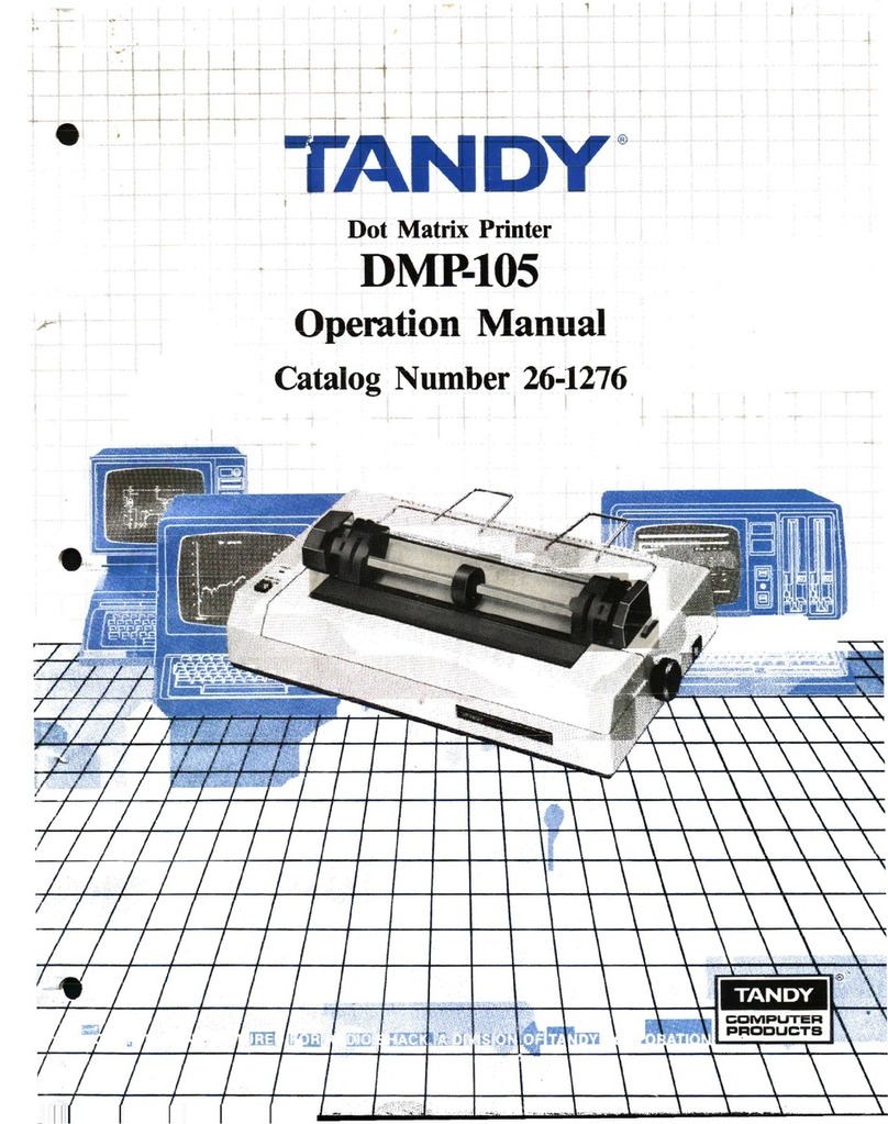
Tandy DMP-105 Installation manual

it -i
f',» .
i:
i
5
i
m:j.
!.1 !i
:
I"
,,;„„,
i
.
I
!
1-1L
•^^^ mmr (r)
^4
:'
Dot Matrix Printer
DMP-105
Operation Manual
Catalog Number 26-1276


Contents
Introduction 1
I/Description of the DMF105 3
2/Setting Up the DMF105 7
Paper Separator Installation ,7
Tractor Installation and Removal 7
Paper Loading 9
Ribbon Installation Replacement 12
Setting Print Function Switches 4DIP Switches) 14
Connecting the DMP-105 to aPower Source 14
Carriage Movement Test 15
Self-Test „is
Connecting the DMP-105 to aComputer ,.16
rower-u psequence ..................,.„,.,,.„,,„,„,,,„,.,,, 16
3/Using the DMP-105 (General Printer
Operation) n
Control Codes 17
Sending Control Codes from BASIC IS
Character Printing Mode ,18
Graphics Mode 18
Selecting aPrint Mode 19
4/Print Font Styles and Character Widths .21
Selecting Font Styles 21
Standard Character Font Style 22
Graphics Characters •„„„„ ,..... 22
Wrap-Around «23
Elongated Characters ........... 23
Bold Characters 24
Mixing Bold and Elongated 24
5/General Control Codes is
Line Feed Codes (LF> 25
Special Line Feed Codes 25
Carriage Return (CR) 16
Ignored or Undefined Codes 26
DMP-105 Buffer Operation 27
6/Charaeter Printing Mode m
Repeat Printing 29
Underline Printing 29
Print Head Positioning 30
Printing Directions 32

7/Graphics Mode 33
Printing Graphics Patterns 34
Line Feed 36
Repeat Function 36
rniit tLrCHSJij ^m.^...^..*,... ........i....ir....niMu ji
Leaving Graphics Mode 37
Mixing Modes on the Same Line 37
Freehand Drawing ,,37
Appendix A/Control Code Summary 39
Appendix B/Interface 41
Parallel Interface 41
Serial Interface ............ „,„„„,.,., 44
Appendix C/Charaeter Sets 47
94 ASCII Code 47
32 European Symbol Code ,43
30 Block Graphic Code ..,....,. 49
Appendix D/Programming Information ...... si
Appendix E/Care and Maintenance &
Printing Limits (Duty Cycle) 55
Appendix F/Schematic Diagram 57
Appendix G/Specifications m

Introduction
Congratulation* for selecting this Tandy compute- product! The DMP-105 is a
dot-matrix printer which can perform avariety of different printing operations.
For instance, it can print:
•Normal r.harjitrrrrs (Nfirmal, (^nndrnsrrl and Compressed)
•Graphics characters.
The DMP-105 operate.? in turn modest
•Character Priming Mode for output of program listings, report writing, or the
creation of any text documentation,
•Graphics Mode for drawing pictures, figures. Or graphs.
In the rtwivteT Printing Mode, the nMP-ICfi prints monospaced. &7 dot-
matrix characters.
In Graphics Mode, you can use graphic data to draw just about any type of
graphic configuration you desire.
You can use two types: of paper with the DMP-105:
•Standard (4*—9,3* wide) computer fan fold forms with guide holes. The
Printer can aiso print one original p(ut one carbon copy.
•Standard (4* —9-5 *> single-sheet typewriter paper.
nrhw .«ifiwflr(»-(v>nTrrtllert fiwriirc-t, Include:
Bidirectional minimum-distance access carriage motion.
»Full, half, 3wl J/4 Forward Line Feed.
•Underline, capability.
and much more?


1/Description of the DMP-105
Carefully unpack the DMP-105, being sure to locate ihe Ribbon Cassette and [he Paper Separator.
Keep lite empty box and packing material just in ease you ever need to transport the Printer.
Be sure t& remove the Yellow Band from the Carriage -
Figure f. Removing the Yellow Band
It's important iu L"ttouic familiar with lIk: DMP-IQ3 nefnre yon <&t [1 up and
bejPTi j^ing ii.

Figure 2. DMP-10S (Top View)
(T) Power ON/OFF Switch, Press [he side of the switch marked fto turn ihe
power ON, Press the switch the other way 10 turn the power OFF, Note that
turning the power OFF and ON during operas ion may cause loss of the
current program,
©POWER ON Indicator. This indicator will illuminate when the DMP-105 is
properly connected and the Power ON/OFF Switch is set to ON.
(J) ON-LINE/OFF-LINE Switch. When this switch is pressed in, the Printer is
placed ON-LINE, When it is pressed again and released, the Printer is
placed off-line.
(3) Platen Pressure Lever. This. lever has two positions. One is Release. Tor the
tractor feed feature (toward the front of the Printer); the other is Friction,
fpr the friction feed Feature (toward the rear of the Printer),

©Paper Bail. For optimum print quality, keep the Bail down on the paper.
(6) Tractor Feed. This Tractor Feed is removable. Sec Selling Up the DMP-105
tor details or using the Tractor Feed. You can remove the Tractor when
priming on single-shed paper.
@Tractor Cam. When the Cam is moved toward the rear or the Printer, the
TrftCtOr can slide from side to aide, and when moved toward the front, it is
locked into position.
(§) Paper Feed Knob. Turn this knob to manually advance the paper,
(f) Paper 1risen iun Opening. Be sure the paper eniers (he DMP-105 hert.
®Platen.
@Top Cover.
@Transparent Cover, This Cover may be opened while handling ihe Paper
Bail.
@Hole Cover. Pui this Cover in place when the Tractor is removed.
@Paper Separator.
Model II users: If aBASiC program srnps txmifion because of aPrinter error,
typing- CONTCiEEB) will cause printing [0 resume, However the entire con-
tents of the print buffer will be printed, scar ting with the current Print Head po-
sition.
Figure 3. DMP-105 (Rear View)
Power Cord. Plug the power cord into awall outlet or approved power
strip,
®Parallel Interface Connector. If your computer has parallel interface
capabilities, connect the cable here. 3« Selling L*|t lire DMP-1(Mi for the
right cable for your computer.
(3) Serial Interface Connector, If you have aColor Computer, tujuiect the ca-
ble to the serial interface connector indicated. See Setting Up (he DMP-105
for the right cable for your Color Computer
.
@> Priit Function (DIP) Switches. The settings of these Switches wilt determine
exactly how your Printer prints in any situation. Such parameters ubaud
rate (6G0 or 24U0 baud) or whether you're using the serial or parallel inter-
face must be set via these Switches.

2/Setting Up the DMP-105
The following Start -Up Checklist is as'Jfiimaty of how to set up your Primer.
You should follow this procedure every time you start -up the Printer —NOT
JUST THE FIRST TIME.
Kind agood spot for your Printer. Be sure to consider:
*Th.e Printer should be placed on asturdy work surface.
•Lhe length of the printer cable will determine how far from your computer
you can place the Printer.
*Paper takes up space. Be sure to leave enough room for smooth paper
flow.
•Don't place the Printer near noise generators such as refrigerators and
industrial equipment.
Be sure the Power Switch (on the right side of the Printer) is OFF.
Remove the packing materials,, including the Yellow Band.
Install continuous form fartfold paper or single-sheet paper.
Check the Ribbon Cassette. If it has not been installed, see Ribbon Insfal-
ttrion/Rfplnfemeat.
Set the Print Function (DIP) Switches (on the rear side of the Printer).
Connect the AC power plug to a3-wire, 120 volt, 60 Hz grounded AC
outlet (220/240 V. 50 Hz where the unit is so marled),
Check to see if the Printer is ready by running the Self-Test.
GConnect the interface cable from the computer to the printer interface
connector,
QTurn the Power ON and check that the Power ON Indicator (on the Con-
trol Panel) is illuminated.
Place the ON-LINE/OFF-LINE Switch in the ON-LINE position,
Be sure that the Top Cover is closed securely.
Paper Separator Installation
Install the Paper Separator by inserting the tips of the Separator into holes
provided on the top of the Printer (behind (he Paper Insertion Open in*}.
Tractor Installation and Removal
This Printer can be used with either the Tractor Fe*d system or the Friction
Feed system. The difference is that ihe Tractor Feed system is used with paper
which has jjuide holes on both edges, while the paper used with the Friction
Feed system does not have these holes.
The Friction F«d system may be used with the Tractor installed; however, bet-
ter operation can be achieved if it is removed —especially when using single
sheets of paper.

Removing the Tractor
1. Set the Power ON/OFF Switch to OFF,
2- Open the "T dp Cover.
i. Move the Paper Bail forward (toward [he front of the Printer).
4. Hold the front bar of the Traclor in your hard and pull upward; then push
it away and remove the Tractor.
5. Move the Paper Bail backward.
6. Close the Top Cover,
Installing the Tractor
1
.
Set ihe Power ON/OFF Swiich to OFF.
2. Open the Top Cover and remove the Hole Cover.
3. Move (he Paper Bail forward (toward the front of the Fruiter},
4. Place the pins in the Iractor onto the cutouts, then push down on the front
of the Tractor until the Tractor is securely locked into position.
5. Move the Paper Hail backward.
6. Close the Top Cover
.
Figure 4, Installing the Tractor

Paper Loading
Warning! When loading paper (single-sheet or fanfold), be sure the paper cor-
rectly enters the Paper Insertion Opening.
It is very important that the paper enters the DMP-105 straight. The paper must
be directly behind the Printer or paper skewing or jamming may occur. Proper
positioning of the Paper Separator is also Important to help prevenl paper
jamming.
PRINTER
_
PAPER
WRONG RIGHT
If the fanfold p&pa :*> correct^ loaded, i! should enter between the bod> nr the
Primer and the Paper Separator. Once the paper is loaded and power is ON.
press to set the ON-LiNE/OhP-LlNE Switch to ON-LINE. Then you may begin
printing.
Single-Sheet Paper Loading
1. Re sure rhp Pnwer Swirch UOFF.
2. Remove the Tractor and set the Hole Cover in its place .(See Tractor Instal-
lation ami Hrmnvul )
3. Move the Platen Pressure Lever forward (toward the front of ihe Printer),
4. Open the Transparent Cover and tilt the Paper Bail forward.
5. Insert the paper into the Paper Insertion Opening and push the Platen Pres-
sure Lever back toward the rear side of the Printer. Use ihe Paper Feed
Knob to pull the paper around until it appears between the Platen and the
Prim Heail
6. Move the Platen Pressure Lever forward to align the paper. Push the Platen
Pre«iir* Lever back again
7. Tilt the Paper Bail back lowatd the rear side of the Primer.
8. Close the Transparent Cover.
Warning? The nap between the Print Head and (he Platen is mechanically ad-
justed prupcrlv at the factory. Do not lr> to admsi it, If it looks like il is out
of position, contact your total Radio Shack Computer Setvice Center,

Figure 5PW9-B Wiring SHo
Hints and Tips On Single-Sheet Paper Loading...
*With the paper properly installed, printing will continue until the paper passes
the Paper Empty Sensor. The Printer will then go OFF-LINE. First, press to
release the ON LINE/OFF-LINE Switch to OFF-LINE. Nevr, insert another
piece of paper and turn the Paper Feed Knob to advance tlie paper. When the
paper is in place, press the ON-LINLVOFF-LINE Switch again and the
DMP- 105 wili continue printing from where it left off, wllhuut luss of data in
the print buffer,
*Remember to set the Platen Pressure Lever and the Paper Bail kmajd the icar
of the Printer while using single-sheet paper.
*When you want to print afew more lines after the paper has passed ilie Pav*i
Empty Sensor, press the ON-LINE/OFF-LINE Switch once to set ii to OFF-
TINF; ihen press it again to set it to ON-LINE. This will prinl one more hne.
Just follow this procedure once for each additional line you wish to print.
Fantold Paper Loading
The DMP-IM will accept standard fan fold paper that is from 4* to 9.5* wide.
The paper may mo main <jue urigin.nl plus one copy.
Before using fanfold paper, however, the Tractor unit should he installed.
TO load fanTuld papei lulu the DMP-105;
1
.
Set the Power ON/OFF Switch 10 OFF,
2. Open the Transparent Cover.
3. Gently mp^ft th* Platen Pr*«nre Lever and the Paper Bail toward the front
of the Printer
-
*, Open ihfl Pin F«d Paper Clamps
10

5. Pbss the paper between the body of the Printer and the Paper Separator, In-
sert ih* paper in lo she Parvr ir^nnn Opening t\-\d puih if i-Platen Pccssuro
Lever back toward the rear side of the Printer. Use lhe Paper Feed Knob to
pull ihe paper around until it appear between the Platen and the Prim Head.
Be sure ihe paper bstraight skj tliai ilit hults will line up with the pin feed
sprockets. Move the Platen Pressure Lever forward to align the paper; since
pin feed paper is being used, leave the Platen Pressure Lever in ihe forward
position.
Note: If re-positioning of the Tractors is necessary, move the Tractor Cams
Loward (he rear of the Printer ao that the Trwjtors #nn slid* from aid*
to side; after adjustment, pull the Cams forward to lock the Tractors
into posilion.
6. Close the Pin Feed Clamps to secure the pspcr,
7. Move the Paper Bail toward (h? paper,
8. Close the Transparent CoveT.
(fXT- ^e.
J.
Figure 6. Fanfold Paper Loading
Warning! The gap between the Print Head and the Platen is mechanically ad-
justed properly at ihe factory. Don't try to adjust it. If tl Looks like it 1$ out of
position, ftiitiact youf locaf Radio Shack Computer 5erv lee Center.
Hints and Tips on hant old Paper Loading...
•Remember to set the Platen Pressure Lever toward the front of the Printer
and the Paper Bail toward the rear of the Printer while using fan fold paper.
Be sure that the paper is positioned so ihat it can travel through the Printer
without binding.
Do rial let paper pile up on top of imprinted paper or printed paper may b*
pulled back into the Paper Insertion Opening. This could jam the paper feed
or damage the Printer. 11

Ribbon Installation/Replacement
If the Ribbon Cassette is already installed, simply check to see that it is properly
threaded berw«n the paper and Print Heati,
[f the Ribbon Cassette is not installed, or iT it must be replaced due to excessive
mew, faint iniutirtg., etc., follow this procedure:
1. Set the Power Switch to OFF. (NOTE; When you turn the power OFF. any
InitofwatloB »luicd ]u Uic Printer's bjffer will, automatically be lust,)
2. Open the Top Cover.
3. Gently grasp the Ribbon Cassette and remove the Cassette by lifting it
upward.
Nflte: Ei*ry time you replace the ribbon cassette; clean the (wo ribbon guide
posts (located at the left end of the carriage shaft) with asoft dry
elofn.
4. Unwrap the new Cassette and remove Lhe packing foam.
5. Gently move the Print Head lo the extreme right.
CAUTION: Be sure Printer power is OFF before manually moving rhr
Print Head.
6- Hold the new Ribbon Cassette and pass the ribbon end around the Ribbon
Guide Posts at the left of the Printer; then move trie dinette toward the
right to draw out the ribbon.
7. Gently press the Cassette down until it is firmly secured by the Stopper
Claw of the Cassette Holder.
Do not force the Cassette into place! If ihe Cassette is not properly fitted,
the Cassette Knob will not match up with the shaft from the Cassette
Holder. Do not force the- Cassette down, but fit It in gradually while push-
ing and turning the Cassette Knob in the indicated direction.
8. Once the new Cassette is installed, move the carriage back and forth manu-
ally, lhe ribbon will be gradually inserted between the Ribbon Guide and
Print Head.
y. Keep moving the Carriage and check that the ribbon advances properly. If
the ribbon has not been propeily fitted between lhe Ribbon Guide and Print
Hear] (i.e., into The Print H-ead Rihhmi Guide fle/frl), lhe ribbon f**d will
not Operate smoothly. (See Figure 7.)
in. Glow th* Top Cover.
12

Mbbon Guide Posit
Cassette Knob
Figure 7, Ribbon Cassette Installation
13

Setting Print Function Switches
(DIP Switches)
There are two switches located on the left rear side of (he printer. These
Switches allow you lo customize some of the DMP- 105 features for your own
applications.
When you receive the DMP-105, all **itebei should be set to OFF (i.e., in the
down potftkm). By setting Certain switches ONrtWjw turning Hie DMP-lOS's
power ON, you can select different baud rat« and interface modej- Figure S
and Table Idefine the different switch positions and Sittings.
Remember! The Printer power must be OFF before fo* change any of the
Switches.
uu
—
1
ON s»de
IOFF Sid*
Figure fl. Print Function (DIP} Switches
Table 1. DIP Switch Settings
Pos. Symbol OFF ON
ParalloNScrial
2400 BPSf
600 BPS
Parallel Interface is
available
Serial Interface ifi
available.
When the Serial In-
terface is available.
transmission rale is
Set to 2400 8PS.
When the Serial In-
terface is available,
transmission fate Is
set to 600 BPS.
Connecting the DMP-105 to aPower Source
BeJuie pliiKgiHK the power cord into an AC paw«T outlet, chick the Following:
QIs the Printer Power ON/OFF Switch set to OFF?
Have you LemweU the Yellow Dand from the Carriage?
13 Don'! connect the Printer to your Computer yet.
14

Connect the AC power plug lo a 3-wire. 120 volt, 60 Hz grounded AC outlet
(220/240 V. 50 H* where the unit is so marloed), or to an approved power
strip such as the Plug-In Power Strip (Catalog Number 61-2619) or the
Automatic Po*er Controller, 5W-301 {26-1429).
Carriage Movement Test
The Carriage Movement Test jilluw;, yuu Lo cttcck that the Carriage moves ffeely
from one end of the PlaTen io the other and thai ihe Platen is turning properly.
Printing Is not pei formed during ihe Carriage Movement Teat.
You can run the Carriage Movement Test by following these steps:
t. Set the ON-LINE/OFF-LINE Switch to OFF-LINE and then set the Power
Switch to ON.
2. Th* Carriage first moves toward ;he right until it strikes the Right Switch
which determines the home position at the left; then il moves left until it
reaches the home position.
Press the ON LHMF/OFFUNE Switch to set it to ON-LINE while the Carri-
age is moving toward the left. The Carriage will move back and forth, per-
forming aLine Feed at the end of each line.
3. Turn the power OFF to end the Carriage Movement Test.
Setf-Test
The DMP- 105 has abulli-ln Self-Test feature which lets you check printing
quality and general printer operation before you connect the Printer to your
computer. This is agood time to check that Ihe Print Head Ls set properly
(printing is neither loo faint noi smudged) and that paper is feeding correctly,
The Setf-Test will last for several minuies.
Before running the Self Jest, however, always be surc to load the DMP-105
with wide paper (9,5 "wide) since the Test prints from one end of the Platen to
the other. Printing <m the Plakrt can shurlen the life of (be Platen and the Print
Head,
To run the Self-Test:
1. Plug the Printer into an AC power outlet.
2. Set the ON-LINE/OFF LINE Switch to ON-LINE.
3. Set the Power ON/OFF Switch to ON,
4. Press Ihe ON-LINE/OFF-LINE Switch to aet it to OFF-LINE while the Car-
riage is moving toward the left.
The Printer *ill begin printing rolling ASCII Mcharacters in Slauduid 10
CPI mode.
J. Printing will continue until you turn the power OFF.
15

Connecting the DMP-105 to aComputer
Before making any connections between the Printer and your ctimputeT, be sure
all units arc off!
You must also be sure you have the collect cable for your computer if the
DMP- 10S is to operate property. Table 2describes the printer cables carried by
Radio Shack; Table 3provides aquick reference for printer connection lo-
cations.
Table 2. Computer to DMP-105 Cables
COMPUTER Cable Number
Model I(Keyboard only) 26- 14 11 (available through National
Parts) '
Model I(Exp. interface) 26-1401
Model II/16/2000/DT-1 26-4401
Model Ml/4 2G-1401
Color Computer 26-3020
Model 100 26-1409
Tabid 3: Computer Connection Points
computer Connector
Model L{Keyboard only) Rear side of Keyboard
Model l{Exp. Interface) Left side of E.I
Model 11/16/100/2000 Rear Panel Of Computer
Model iiWQT-1 Underneath Panel
Color Computer Rear Panel of Computer
1. Attach the molded male end of the cable to the connector on the left rear
side of the Printer.
Do not force the plug. If hdoesn't Tit one way, turn it over and try again.
2. Connect the other end of the cable io the Printer JacV of your Computer,
See your computer owner's nianual for spec! fit instructions.
Power-Up Sequence
The specific power-up sequence will depend upon your Computer, We suggest
you consult your computer owner's manual for details on powering up your
computer with peripheral devices (pitch as pihiicis).
In any event, the Power Lamp *ill remain lit while the Printer is ON,
It is essential that the Primer remain ON when connected to the Computer, If
you turn (he power ON or OFF, ur aPrinter la connected but not turned on,
erratic operflTlori of the entire system may olcui.
16
Table of contents
Other Tandy Printer manuals

Tandy
Tandy TRP-100 User manual

Tandy
Tandy DMP 135 User manual

Tandy
Tandy 26-2814 User manual

Tandy
Tandy DMP 106 User manual

Tandy
Tandy DMP-130 User manual

Tandy
Tandy DWP-220 User manual

Tandy
Tandy DMP-130 User manual

Tandy
Tandy DMP 132 User manual

Tandy
Tandy DMP-I05 User manual

Tandy
Tandy DMP 106 User manual