PRINCIPLES OF
OPERATION
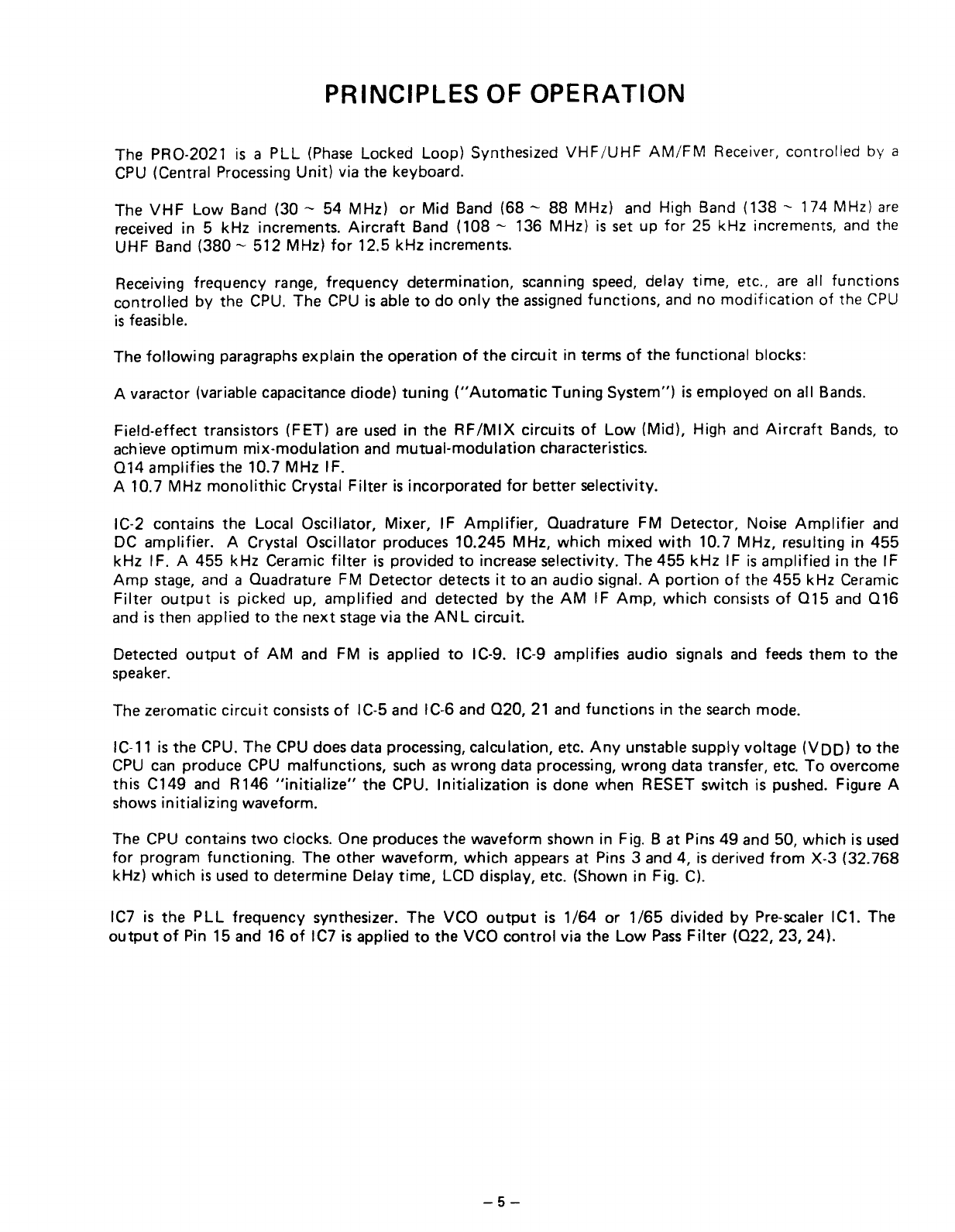
The PRO-2021 is a
PLL
(Phase
Locked Loop) Synthesized
VHF/UHF
AM/FM
Receiver, controlled by a
CPU (Central Processing
Unit)
via the keyboard.
The
VHF
Low
Band (30 - 54 MHz) or Mid Band (68 - 88 MHz) and High Band (138
~
174 MHz) are
received in 5 kHz increments.
Aircraft
Band (108 - 136 MHz) is set up
for
25 kHz increments, and the
UHF Band (380 - 512 MHz)
for
12.5 kHz increments.
Receiving frequency range, frequency determination, scanning speed, delay time, etc.. are all functions
controlled by the CPU. The CPU is able
to
do
only
the
assigned
functions, and no
modification
of
the CPU
is feasible.
The
following
paragraphs explain the operation
of
the
circuit
in terms
of
the
functional
blocks:
Avaractor (variabie capacitance diode)
tuning
("Automatic
Tuning System") is employed on all Bands.
Field-effect transistors (FET) are used in the
RF/MIX
circuits
of
Low
(Mid). High and
Aircraft
Bands, to
achieve
optimum
mix-modulation
and
mutual-modulation
characteristics.
014
amplifies the 10.7 MHz IF.
A 10.7 MHz
monolithic
Crystal
Filter
is incorporated
for
better selectivity.
IC-2 contains the Local Oscillator, Mixer, IF
Amplifier,
Ouadrature FM Detector, Noise
Amplifier
and
DC amplifier. A Crystal Oscillator praduces 10.245 MHz, which mixed
with
10.7 MHz, resulting in
455
kHz IF. A 455 kHz Ceramic
filter
is pravided
to
increase selectivitv, The
455
kHz
IF is amplified in the IF
Amp
stage, and a Ouadrature FM Detector detects
it
to
an audio signa!. A
portion
of
the
455
kHz Ceramic
Filter
output
is picked up, amplified and detected by the
AM
IF
Amp.
which
consists
of
015
and
016
and is then applied to the
next
stagevia the AN L circuit.
Detected
output
of
AM
and FM is applied
to
IC-9. IC-9 amplifies audio signals and feeds them
to
the
speaker.
The zeromatic
circuit
consists
of
IC-5 and IC-6 and
020,
21 and
functions
in the search mode.
IC-11 is the CPU. The CPU does data processing, calculation, etc.
Any
unstable supply voltage
(VDD)
to
the
CPU can praduce CPU malfunctions, such aswrang data processing, wrong data transfer, etc.
To
overcome
this C149 and R146
"initialize"
the CPU.
Initialization
is done when RESET switch is pushed. Figure A
shows
initializing
waveform.
The CPU contains
two
clocks. One produces the waveform shown in Fig.
Bat
Pins 49 and 50,
which
is used
for
program functioning. The
other
waveform,
which
appears at Pins 3 and 4, is derived
from
X-3 (32.768
kHz)
which
is used to determine Delay time, LCD display, etc. (Shown in Fig. Cl.
IC7 is the
PLL
frequency synthesizer. The VCO
output
is
1/64
or
1/65
divided by Pre-scaler IC1. The
output
of
Pin 15 and 16
of
IC7 is applied
to
the VCO
contral
via the
Low
Pass
Filter
(022,
23, 24).
-5-