DESGRIPTlON:
GRYSTAL
OPERATlON*
DG
OPERATION
Socket
ry}
DC
OII11DAC
Slide
Switch
The
Patrolman
™Pro-2 receiver can receive
both
AM
and
FM signais.
This
is done by depressing a
"rocker"
switch to
either
the AM or FM mode on the
front
panel.
If
in
doubt
as to rhe mode, place this switch in
the
position
which
results in best reception at
the
center
of carrier.
An
output
jack
(rear
panel)
can be used for
either
tape
recording
transmissions or for feeding the
input
of an
external
amplifier.
A
phone/speaker
jack rnounted in the
front
panel
allows the use
of.
an
external
phone/speaker.
When
using
this jack,
the
built-in
speaker is automatically
shut-off. An ideal external speaker is the Realistic Model
SP-ISO,Cat.
No.
20-1500.
This
unit
has an adjustable squelch con
trol
that elim-
inates
background
noise in the absence of a signal.
When
adjusting
the conrrol, rorate it clockwise
until
back-
ground
noise is barely audible,
The
squelch
circuit
is
completely electronie
and
does
not
use relays.
For satisfactory performance an antenna of no less
than
8 ft. can be used. However, for best results,
the
antenna
should be specifically designed for the desired frequency.
A
matching
dual
band
antenna
is available from
Radio
Shack, Cat. No. 20-015.
An
AC/DC
slide switch is located on the
rear
panel.
Wh
en in the DC posirion,
the
switch disables
the
AC
power
supply and conneets
the
DC
power
to the socket
on the back panel. A
plug
is inc1uded for conneetion
to a 12VDC
supply
or to the Realistic
portable
12 volt
battery pack, Cat,
No.
20·1501.
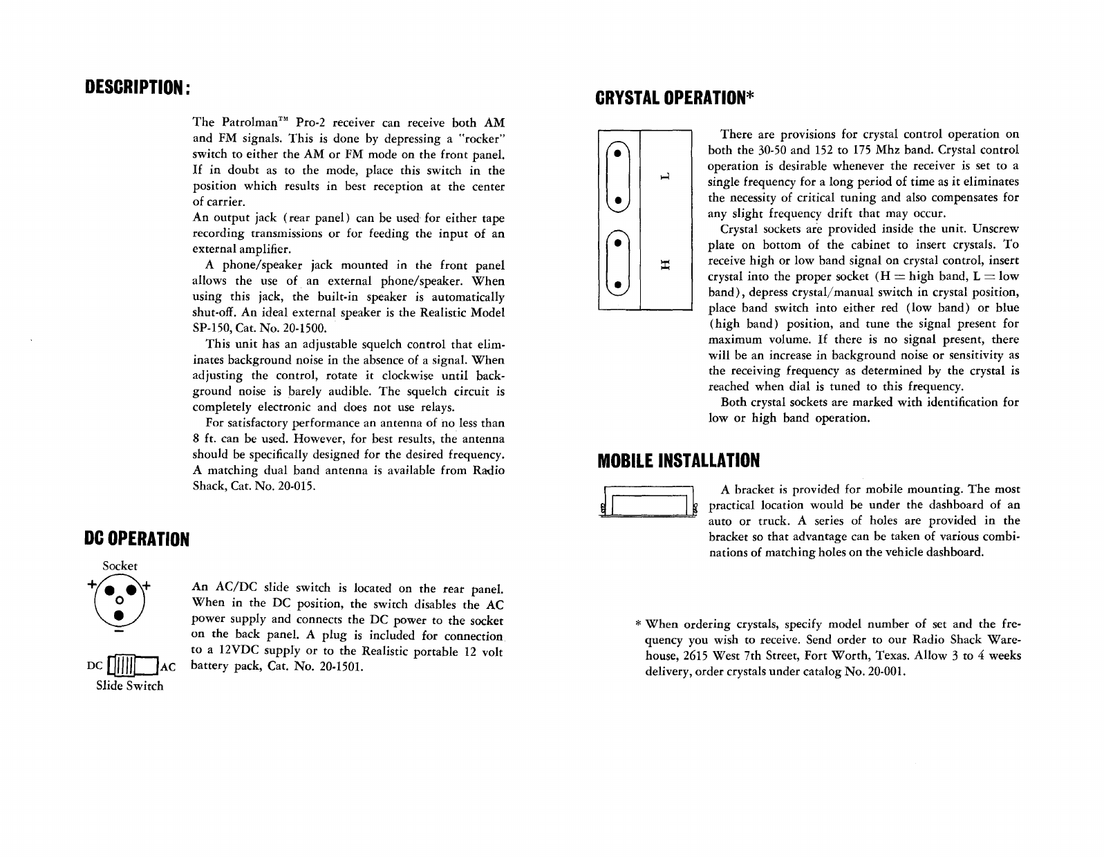
There
are provisions for crystal con
trol
operation
on
both
the 30-50 and 152 to 175
Mhz
band. Crystal
control
operation is desirabie
whenever
the receiver is set to a
single frequency for a
long
period
of
time
as
it
eliminates
the necessity of critical
tuning
and also compensates for
any
slight
frequency
drift
that
may
occur.
Crystal soekets are
provided
inside the
unit.
Unscrew
plate
on bottorn of
the
cabinet
to insert crystaIs.
To
receive
high
or
low
band
signaion
crystal control, insert
crystal
into
the
proper
socket
(H
=
high
band, L=
low
band),
depress
crystal/
manual
switch in crystal position,
place band switch
into
either
red
(low
band)
or
blue
(high
band)
position,
and
tune
the
signaIpresent for
maximum
volume.
If
there
is no signal present,
there
will
be an increase in
background
noise or sensitivity as
the receiving frequency as determined by the crystal is
reached
when
dial
is
tuned
to this frequency.
Both
crystal soekets are
marked
with
identification for
low
or
high
band
operation.
MOBILE
INSTALLATION
GA bracket is provided for mobile
mounting.
The
most
practicallocation
would
be
under
the dashboard of an
~====bl;
auto
or truck. A series of holes are provided in
the
bracket so
that
advantage can be taken of various combi-
nations of
matching
holes on
the
vehic1e dashboard.
*
When
ordering
crystals, specify
model
number
of set and
the
fre-
quency you wish to receive. Send
order
to
our
Radio Shack
Ware-
house, 2615
West
7th Street,
Fort
Worth,
Texas. Al10w 3 to 4 weeks
delivery,
order
crystals
under
catalog
No.
20-001.