INSTALLATION
A
good
installation
will
make
the
most
of
the
PRO-9's capabilities. Loss
of
the
tiny
signal at the
antenna
is
avoided
by
correct
antenna
adjustments
and
by
installing
a good
quality
foam
coaxial cabie. The
antenna
that
you
choose, and
how
you install
it,
will
have a great
effect
on
how
weil
your
unit
will
work.
BASE
INSTALLATION:
An antenna, such as a
ground-plane
(Cat. No.
20-176)
mounted
as
high
above
the
ground
as
practical
will
greatly
increase
the
signaI
strength.
For
proper
input
matching,
a 50
ohm
lead-in
coaxial
cable such as RG
58/u
[Cat,
No.
278-970)
should
be used. A
Motorola
type
antenna
adapter
plug
(Cat, No.
278-208,
or
equivalent
to
Cinch-Jones No. 13B
or
H.H
.Smith
No.
1200)
will
have
to
be
installed
on
the
receiver end of the cable in
order
to
utilize
the
antenna
connector
located on
the
rear (back) panel
of
the
unit.
,.
~
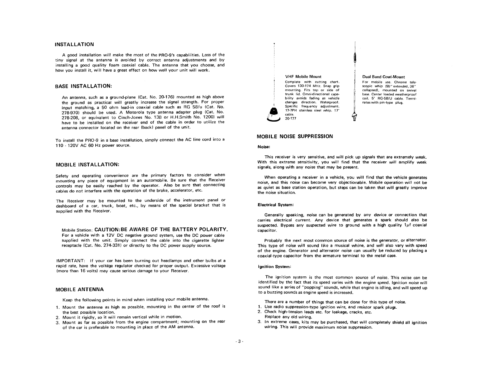
VHF Mobile
Mount
Complete
with
cutting
chart.
Covers 130-174 MHz. Snap grip
mounting.
Fits
top
or side of
trunk
lid.
Omni-directional
capa-
bility avoids
fading
as
vehicle
changes direction. Waterproof.
Specific
frequency
adjustment.
17-7PH stainless steel
whip.
17'
cabie.
20-177
,
j
J
Dual Band Cowl-Mount
For
mobile
use.
Chrome
tete-
scopic
whip
(55"
extended,
36"
collapsedJ,
mounted
on swivel
base. Center loaded
weatherproof
coil. 5'
RG-58/U
cabie.
Termi-
nates
with
pin-type
plug.
To install
the
PRO-9
in a base
installation,
simply
conneet
the
AC
line
cord
into
a
110
-
120V
AC 60 Hz
power
source.
MOBILE
INSTALLATION:
Safety
and
operating
convenience
are
the
primary
factors
to
consider
when
mounting
any
piece
of
equipment
in an
automobile.
Be sure th at
the
Receiver
controls
may
be easily reached ev
the
operator.
Also
be sure th at
connecting
cables do
not
interfere
with
the
oparation
of
the brake,
accelerator,
etc.
The
Receiver
may
be
mounted
to
the
underside
of
the
instrument
panel or
dashboard
of
a car,
truck,
boat,
etc., by means
of
the
special
bracket
that
is
supplied
with
the
Receiver.
Mobile
Station:
CAUTION:BE AWARE OF THE
BATTERY
POLARITY.
For
avehicle
with
a
12V
DC negative
ground
svstsm. use
the
DC
power
cable
supplied
with
the
unit.
Simply
conneet
the
cable
into
the
cigarette
lighter
receptacle (Cat. No.
274-331)
or
directly
to
the DC
power
supply
source.
IMPORTANT:
If
your
car has been
burning
out
headlamps and
other
bulbs
at a
rapid
rate, have
the
voltage
regulator
checked
for
proper
output.
Excessive voltage
(more
than
16
volts)
may
cause serious damage
to
your
Receiver.
MOBILE
ANTENNA
Keep
the
following
points
in
mind
when
installing
your
mobile
antenna.
1.
Mount
the
antenna
as high as possible,
mounting
in
the
center
of
the
roof
is
the
best possible
location.
2.
Mount
it
rigidly,
so
it
wil!
remain
vertical
while
in
motion.
3.
Mount
as
far
as possible
from
the
engine
compartment;
mounting
on
the
rear
of
the
car is
preferabie
to
mounting
in place of
the
AM
antenna.
-
3-
MOBILE
NOISE SUPPRESSION
Noise:
This
receiver is
very
sensitive, and
will
piek
up signals
that
are
extremely
weak.
With
this
extreme
sensitlvitv,
you
wil!
find
that
the
receiver
will
amplify
weak
signais,
along
with
anv
noise th at
may
be present.
When
operating
areceiver in a vehicle,
you
will
find
that
the
vehicle generates
noise, and
this
noise can become
very
objectionable.
Mobile
oparation
will
not
be
as
quiet
as base
station
operation,
but
steps can be
taken
that
will
greatly
improve
the
noise
situation.
Electrical
System:
Generally
speaking, noise can be generated bv
any
device or
conneetion
that
carries
electrical
current.
Any
device
th at generates a spark
should
also be
suspected. Bypass
anv
suspeered
wire
to
ground
with
a high
quality
1~f
coaxial
capacitor.
Probably
the
next
most
common
souree
of
noise is
the
generator, or
alternator.
This
type
of
noise
will
sound
like
amusical
whine,
and
will
also
vary
with
speed
of
the
engine.
Generator
and
alternator
noise can
usually
be reduced bv
placing
a
coaxial-type
capacitor
from
the
armature
terminal
to
the
metal
case.
Ignition
System:
The
ignition
system is the
most
common
souree
of
noise.
This
noise can be
identified
by
the
fact
that
its speed varles
with
the engine speed.
Ignition
noise
wil!
sound
like
a series
of
"poppinq"
sounds,
while
that
engine is
idling,
and
will
speed up
to a
buzzing
sounds as engine speed is increased.
There
are a
nurnber
of
th ings
that
can be
do
ne
for
th is
type
of
noise.
1. Use
radio
suppression-type
ignition
wire,
and resistor spark plugs.
2. Check high-tension leads etc.
for
leakage, cracks, etc.
Replace
any
old
wiring.
3. In
extreme
cases,
kits
may be purchased,
that
will
completely
shield
all
ignition
wiring.
This
will
provide
maximum
noise suppression.