Tandy Radio Shack Realistic PATROLMAN PRO-3A User manual

Please read before using this
equipment
OWNERS
MANUAL
PATROLMAN PRO-3A
VHF/UHF
3 BAND MONITOR
RECEIVER
PROFESSIONAL
SERIES Catalog No.
20-452

PRO-3A Monitor
Receiver
PRO-3A
Monitor
Receiver
General Description General Specifications
Your
PRO-3A
Patrolman
Receiver tunes th ree bands
allocated
by
the
FCC
to
service and business
communications.
They
are:
The
PRO-3A
is an
extremely
sensitive receiver.
With
a
full
complement
of
circuits
and cornponents, it is
nearly
as
sentitive
as
any
receiver
for
its
tuning
ranges can
be.
lts
natural noise level is
comparable
to
a
one-third
microvolt
signal-and
that
limiting
noise can be heard
merely
by
turning
up
the
audio
volume
control.
These bands
carry
a
remarkable
variety
of business and emergency
radio
services. Best
known
are
Fire
and Police,
but
others
include
Forestry/Conservation,
Hospitais, Physicians,
Emergency
Communications.
A
list
of
sixteen general classes
appearing in
the
FCC
regulations
is given on page '2, and every class
includes
several users. No
individual
allocations
are given
there
because generally 'all bands
are used by all services.
This
great
sentitivity
is necessary
for
remote
areas and in emergency
operating
conditions.
But
circuits
designed
for
high
sensitivity
are
often
subject
to
intermodulation
problems
if
used in
very
strong-signal areas.
Also,
adjacent-channel
transmitters
are
more
likely
to
be
operating
in urban and
metropol
itan areas
than
in
remote
regions. The
PRO-3A
features a
really
effective
10.7
MHz
filter,
placed in
its IF
input
circuit.
This
reduces or
eliminates
adjacent-channel or strong-signal
interference.
Note:
These are given in general
form
only,
since
REALISTIC
does
not
believe
in
buying
ro or designing
to
numerical
specifications.
The
latter
are subject
to
variables
not
c1early related
to
performance,
just
as
selectivity,
the
number
of
transistors or
IC's
indicate
in an average way
the
quality
of
a
circuit
but
do
not
prove
one
circuit
will
outperform
another
in real
operating
conditions.
Our
philosophy
is
that
a piece
of
equipment
should
be evaluated in
terms
of
what
it
does
for
the
purchaser, its
quality
and relative value being based
upon
merit
and
observed
performance
in real
life.
Thus
REALISTIC
designs
toward
achieving a
certain
result, ... regardless
of
cost,
regardless
of
lab measurements, regardless of
competitive
advertising
claims. Results are
determined
by
your
application
of
our
finished
result.
Good
installation
is
extremely
important
since a
poorly
installed or
a
wrongly
placed antenna can
result
in a 90% or even greater
signalloss.
And
an
inadequate speaker system can be
almost
as
effective
in
reducing
equipment
performance.
The
following
figures are
offered
only
as a guide,
not
as a guarantee
of
equipment
performance:
This
equipment
is designed
to
operate
from
either
117
VAC
or 12
VDC
negative
ground.
If
it
fails
to
operate, and
there
is no c1ear reason
for
the
failure,
first
check
the
supply
switch.
This
switch
entirely
disconnects
the
supply
components
that
are
not
in use.
Also,
before
connecting
the
PRO-3A
receiver
to
a
DC
power
supply,
check
the
voltage
polarities.
Attempting
to
operate
the
negative-ground
PRO-3A
from
one
of
the
rare
positive-ground
automotive
or
boat
electrical systems,
or
from
a
wrongly
connected
battery,
will
at least
blow
a fuse.
It
may
do
further
damage, so
that
expensive and
time-consuming
repairs are
necessary
before
the
PRO-3A
can be used again. The
Radio
Shack
warranty
does
not
apply
to
any
damage caused by
this,
inadequate
lightning
protection,
or
other
improper
connections.
30 - 50
MHz
152
-
174
MHz
450
-
470
MHz
VHF
LO
VHF
Hl
UHF
Designed
for
the
user,
the
PRO-3A
offers
more
utility
than
any
other
receiver
in its class.
It
is large enough
for
base
station
operatien.
and has all necessary
features
of
SQUELCH,
narrow-band
filter,
and several-band
operation.
It also is
light
enough
to
be carried
into
hard-to-reach areas or
mounted
in cars,
trucks,
boats
or airplanes.
And
it
uses a
remarkably
small
amount
of
power.
For
example,
a single car
battery
should
power
the
PRO-3A
for
better
than
200
hours
of
continuous
operation
before
needing
arecharge.
Another
filter
is
included
to
improve
the
readability
of
very
weak
signais. A
low-pass
audio
filter,
also
controlled
from
the
front
panel, can be
switched
in
to
reduce the
effects
of
inherent
circuit
noise
when
listening
to
avoice signal
that
is
"buried
in the
noise."
By
reducing
the
audio
bandwidth
of
the receiver,
the
filter
emphasizes the desired
audio
signal.
The
PRO-3A
is
remarkably
easy
to
use.
But
it is an
up-tc-date,
complex
circuit
consisting
of
25 separate transistors pi us 20
more
in its
integrated-circuit
IF
section,
10
diodes
and one zener.
All
are
mounted
on a steel chassis,
which
in
turn
is instalied in a steel
cabinet
provided
with
a
mounting
bracket
designed
for
mobile
installation.
The
PRO-3A
is an
important
engineering
achievement,
but
designed
for
practical appl ications.
GUARANTEE:
The
REALISTIC
guarantee is stated on
the
Fact
Tag packed
with
the
equipment.
It
is in
effect
from
coast to coast.
At
any
time,
REALISTIC
equipment
may be restored
to
new
condition
with
original
parts
with
MINIMUM
delay
anywhere
in
the
U.S.A.,
usually
in
your
own
neighborhood.
It
is
NOT
necessary
to
return
REALISTIC
equipment
to
our
laboratories
in 98%
of
the
cases.
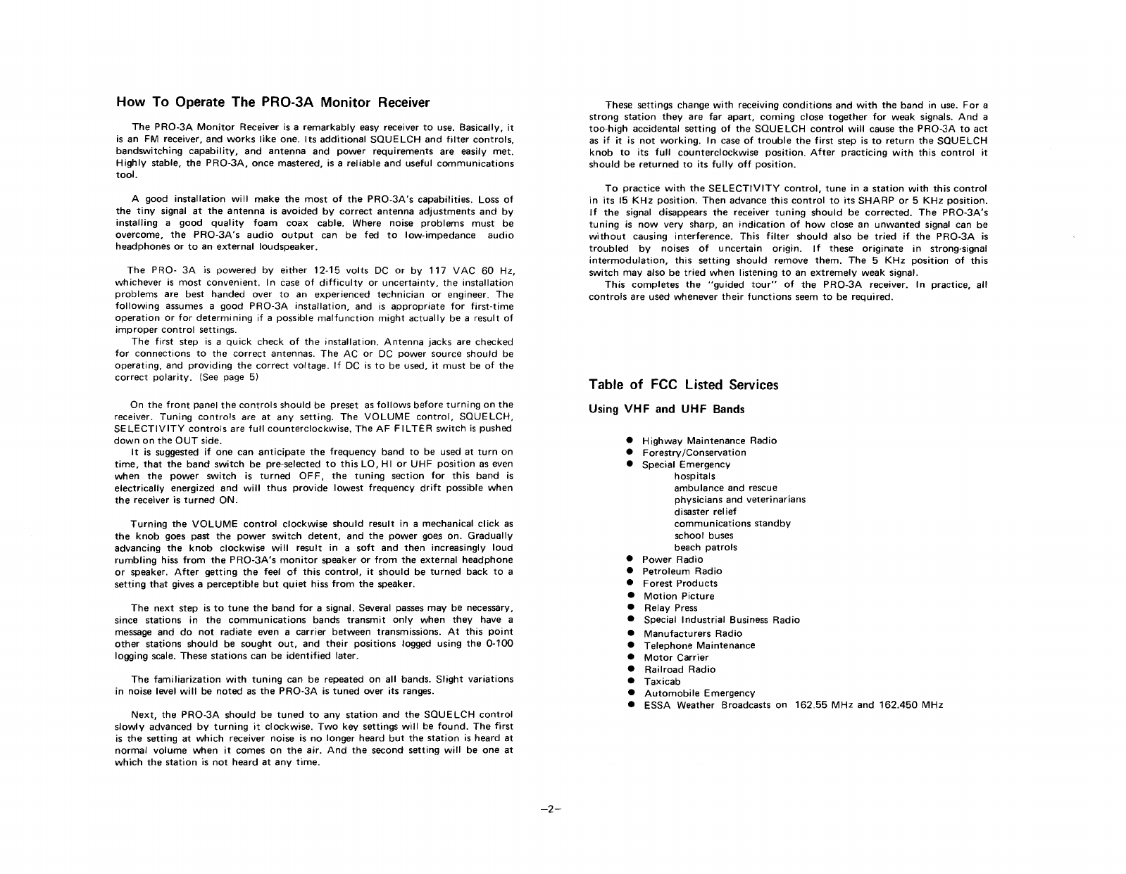
General Specifications List
•
Tuning
Ranges:
VHF
LO,
30-50
MHz.
VHF
Hl,
152-174
MHz.
UHF,
450-470
MHz.
•
Antenna
Connections:
50-ohm
coax. One
for
VHF
LO and Hl bands.
Another
for
UHF
band.
•
Sensitivity:
1
microvolt
for
20 dB
quieting.
•
Selectivity:
5
KHz
position-6
dB @±5
KHz.
15
KHz
position-3
dB @
±35
KHz.
• IF
frequency:
10.7
MHz.
•
Audio
Output:
2
watts
into
8ohms.
The
PRO-3A
will
operate
into
a 4
thru
16
ohms
load.
•
Solid-state
Components:
25 transistors, 2 IC, 10 diodes and 1 zener.
•
Power
Input:
117
VAC
60 Hz or
12-15
VDC,
negative
ground
only.
-1-

How To Operate The PRO-3A Monitor
Receiver
The
PRO-3A
Monitor
Receiver is a
remarkably
easy receiver
to
use. Basicallv, it
is an FM receiver, and
works
Jike one.
lts
additional
SQUELCH
and
filter
controls,
bandswitching
capability,
and
antenna
and
power
requirements
are easily
met.
Highly
stable,
the
PRO-3A,
once mastered, is
areliabie
and useful
communications
tooI.
A good
installation
will
make
the
most
of
the
PRO-3A's
capabilities. Loss
of
the
tiny
signaI at
the
antenna
is
avoided
bv
correct
antenna
adjustments
and by
installing
a
good
quality
foam
coax
cabie. Where noise
problems
must
be
overcome,
the
PRO-3A's
audio
output
can be fed
to
low-impedance
audio
headphones or
to
an
external
loudspeaker.
The
PRO-
3A
is
powered
by
either
12-15
volts
DC or by 117
VAC
60 Hz,
whichever
is
most
convenient.
In case of
difticulty
or
uncertainty,
the
installation
prablems
are best handed over
to
an experienced
technician
or engineer. The
following
assumes a
good
PRO-3A
installation,
and is
appropriate
for
first-time
operation
or
for
determining
if a possible
malfunction
might
actually
be a result of
improper
control
settings.
The
first
step is a
quick
check
of
the
installation.
Antenna
jacks are checked
for
connections
to
the
correct
antennas.
The
AC or DC
power
souree
should
be
operating,
and
providing
the
correct
voltage.
If
DC is
to
he used,
it
must
be
of
the
correct
polarity.
(See page 5)
On
the
front
panel
the
controls
should
be preset as
follows
before
turning
on
the
receiver.
Tuning
controls
are at
any
setting. The
VOLUME
contra
I,
SQUELCH,
SELECTIVITY
controts
are
full
counterclockwise.
The
AF
FIL
TER
switch
is pushed
down
on the
OUT
side.
It
is suggested
if
one can
anticipate
the
frequency
band
to
be used at
turn
on
time,
that
the
band
switch
be pre-selected
to
th is
LO,
Hl
or
UHF
position
as even
when
the
power
switch
is
turned
OFF,
the
tuning
section
for
this
band
is
electrically
energized and
will
thus
provide
lowest
frequency
drift
possible
when
the
receiver is
turned
ON.
Turning
the
VOLUME
contral
clockwise
should
result in a mechanical
click
as
the
knob
goes past the
power
switch
detent,
and
the
power
goe.s
on.
Gradually
advancing
the
knob
clockwise
will
result in a
soft
and
then
increasingly
loud
rumbling
hiss
from
the
PRO-3A's
monitor
speaker or
from
the external
headphone
or speaker.
Af
ter
getting
the
feelof
this
control.
it
should
be
turned
back
to
a
setting
that
gives a
perceptible
but
quiet
hiss
fram
the
speaker.
The
next
step is
to
tune
the
band
for
a signal. Several passes may be necessary,
since
stations
in
the
communications
bands
transmit
only
when
they
have a
message and
do
not
radiate even a
carrier
between
transmissions.
At
this
point
other
stations
should
be
sought
out,
and
their
positions
logged using the 0-100
logging scale. These
stations
can be
identified
later.
The
familiarization
with
tuning
can be repeated on all bands.
Slight
variations
in noise level
will
be
noted
as
the
PRO-3A
is
tuned
over its ranges.
Next,
the
PRO-3A
should
be
tuned
to
any
station
and
the
SQUELCH
control
slowly
advanced by
turning
it
c1ockwise.
Two
key settings
will
be
found.
The
first
is
the
setting
at
which
receiver noise is no longer heard
but
the
station
is heard at
normal
volume
when
it
comes on
the
air.
And
the
second
setting
will
be one at
which
the
station
is
not
heard at
any
time.
-2-
These settings change
with
receiving
conditions
and
with
the
band in use.
For
a
strang
station
they
are
far
apart,
comi
ng close
together
for
weak signais.
And
a
too-high
accidental
setting
of
the
SQUE
LCH
control
will
cause
the
PRO-3A
to
act
as
if
it is
not
working.
In case
of
trouble
the
first
step is
to
return
the
SQUELCH
knob
to
its
full
counterclockwise
position.
After
practicing
with
this
control
it
should
be
returned
te
its
fully
off
position.
To
practice
with
the
SELECTIVITY
control.
tune
in a
station
with
this
control
in its 15
KHz
positron.
Then
advance
this
control
to
its
SHARP
or 5
KHz
position.
If
the
signal disappears
the
receiver
tuning
should
be
corrected.
The
PRO-3A's
tuning
is
now
very
sharp, an
indication
of
how
close an
unwanted
signal can be
without
causing
interference.
This
filter
should
also be
tried
if
the
PRO-3A
is
troubled
by noises
of
uncertain
origin.
If
these
originate
in strong-signaI
intermodulation,
this
setting
should
remove
them.
The 5
KHz
position
of
this
switch
mayalso
be
tried
when
listening
te
an
extremely
weak signal.
This
completes
the
"guided
tour"
of
the
PRO-3A
receiver. In practice, all
contrals
are used whenever
their
functions
seem
to
be
required.
Table of
Fee
Listed
Services
Using VHF and UHF Bands
• H
ighway
Maintenance Radio
•
Forestry
/Conservation
•Special
Emergency
hospitals
ambulance
and rescue
physicians and veterinarians
disaster
relief
communications
standbv
school buses
beach
patrots
•
Power
Radio
•
Petroleum
Radio
•
Forest
Products
•
Motion
Picture
• Relay Press
• Special
Industrial
Business
Radio
•
Manufacturers
Radio
•
Telephone
Maintenance
•
Motor
Carrier
•
Railroad
Radio
•
Taxicab
•
Automobile
Emergency
• ESSA Weather Broadcasts on 162.55
MHz
and
162.450
MHz

Cutting
instructions
tor
UH F and
VH
FAntennas
•
o
CUTTING
20-
I
77
ANTENNA
UHF
450-470
MHz
15"
~-----'---_-L.
450 460 470
OPERATING
FREQUENCY
MHz
11"
ANTENNA
LENGTH
16'
152-174
MHz
160 170
OPERATING
FREQUENCY
MHz
IS'
16"
14'
L-
-'-
--""'--
150
ANTENNA
LENGTH
The
Radio
Shack No.
20-177
antenna is a one
quarter
(152-174
MHz)
or five-eighths
(450-470
MHz)
wave
vertical
designed
tor
automotive
trunk
lid
mounting.
A special
clamp
in the
antenna
base
fits
into
the space
between
lid
and car
body
so
that
no
hole
cutting
is
required.
Complete
installation
instructions
are suppl ied
with
the antenna.
Minimum
distance
from
antenna
to
edge
of
the
metal
mounting
surface is
preferably
five
or
more
antenna
lengths.
The
two
charts
at the
right
indicate
most
efficient
lengths, as
measured
from
the
tip
of
the
antenna
to the
top
of
the
set screw
fitting.
The
antenna
length
is
adjusted
to
5/8
wavelength at
450-470
MHz
to
improve
its
horizontal
gain at a
slight
cost
in high-angle gain.
lts
practical
effect
is
about
equal
to
a
doubling
of
the
transmitter
power.
Antenna
reliability
will
be
improved
if
at assembly all
contacting
metal surfaces
are cleaned and
then
coated
with
a
thin
layer
of
water
pump
grease or
equivalent.
The base
fittings
hould
be
dismantled,
cleaned, and
checked
about
once per year.
14'
.......
-'----''----'---'---'-
150 160 170
OPERATING
FREQUENCY
MHz
5.0"L....-
__
-L
...L-
450
460 470
OPERATING
FREQUENCY
MHz
ri
The
Radio
Shack
No.
20-176
antenna
is a
wideband
quarter-
wave
gound-plane
antenna
for
152-174
MHz
or
450-470
MHz.
It
is designed to be used at
fixed
or
portable
stations.
For
best
performance
at a given
frequency
its
whip
and
radials
should
be
cut
as
follows.
During
installation
all
four
radials are
cut
to
20
1/4"
(152-174
MHz)
or
6
1/2"
(450-470
MHz).
They
are
removed
from
the
assembly,
the
four
end balts
pulled
off,
and each radial is
cut
to
the
correct
over-all
length.
Then
the
balls
are
tapped
back
on.
Next,
the
vertical
radiator
top
plug
is
removed,
and
the
radiator
overall
length
trimmed
to
the
value given in
the
cutting
chart.
After
cutting,
the
antenna
is ready
for
assembly and
installation.
For
best
performance
this
antenna
should
be
instalied
ten or
more
vertical
radiator
lengths
away
from
any large
metal
objects.
Wires,
lightning
proteetion
svsterns,
metal
roots.
and large vehicles
moving
or stored
nearbv
may
influence
qual
ity
of
the
received
signal.
If
performance
of
the
receiver system seems
poor
compared
with
th at
of
other
similar
installations,
the
anten
na
should
be
moved.
UHF
BAND
450-470
MHz
RADlALS 6y';"LONG
ANTENNA
LENGTH
RADlALS
20J,{"
LONG
CUTTING
20-
I
76
ANTENNA
VHF
Hl
BAND
152-
174
MHz
6.0'
17"
15'
ANTENNA
16'
LENGTH
UHF
and
VHF
Antennas
Dual Band
Ground
Plane
For
outdoor
use. 3
heavy-duty,
low
resistance
aluminum
ele-
ments.
2-section
vertical
radiator,
matching
transformer.
Mounting
bracket.
Accepts
PL-259.
20-015,
6 Ibs.
I
I
J
Indoor
Hi-Lo
Antenna
Plug-in
type.
For
indoor
use.
Ru
gged
construct
ion,
center
loaded
coil.
Telescoping
whip,
40"
extended,
16"
collapsed.
Termi
nates
with
pi
n-type
plug.
21-161,
2 Ibs.
Dual Band
Cowl-Mount
For
mobile
use.
Chrome
tele-
scopic
whip
(55"
extended,
36"
cotlapsed},
mounted
on
swivel
base.
Center
loaded
weatherproof
coit.
5'
RG-58/U
cabie.
Termi-
nates
with
pin-type
plug.
Omnidirectional
Indoor
Antenna
For
indoor
or
portable
use. Plugs
directly
in to back
of
PRO-3A
receiver.
22"
overall.
Decoupling
skirt
improves
efficiency.
Chrome-plated.
20-451,
1
1/2
Ibs.
-3-

FRONT
AND
REAR PANEL
CONTROLS
FRONT
REAR
FIG-l
-4-
A
-llluminatad
slide-rule
dial
,
B
-Separate
dial
pointers
for
30-50
MHz/450-470
MHz
and
152-174
MHz.
C
-Tuning
knob
for
30-50
MHz
and
450-470
MHzband.
o
-Tuning
knob
for
152-174
MHz
band.
E
-Power
switch
and
audio
volume
control.
F
-Squelch
eliminates
no-signaInoise.
G
-Selectivity
switch
chooses
broad
or sharp
characteristic.
H
-Band
switch.
I
-Low
impedance
audio
Jack
for
phones
or
external
speaker.
J
-Audio
filter
improves
weak
signaI
readability.
K
-Easily
removed
knurled
mounting
screws.
L
-Steel
mounting
bracket.
M
-Antenna
connection
for
30-50
MHz
and
152-174
MHz
band.
N
-Antenna
connection
for
450-470
MHz
band.
o
~For
P.A.
or
Tape
Input.
P
-OC
Power
Connection
Secket.
Q
-AC
Power
Cord.

ELECTRICAL INSPECTION
Set controlsas follows: (Ref. FIG - 1,
page
4)
1.
Volume
Control
(E):
Off
position
2. Squelch
(F):
Minimum
position
(Counter
c1ockwise)
3.
Selectivity
Switch
(G):
15
KHz
position
4. Band
Switch
(H):
Low
band
position
5.
Audio
Filter
(J):
Out
position
6.
Antenna
Jack
(M,N):
Conneet
anten
na
to
jack
7. AC
Power
Cord
(O}:
Line
cord
to
AC
outlet
(120
V)
Turn
the
Squelch
Control
to
the
minimum
position.
Turn
the
Volume
Control
to
"ON"
and a
rushing
sound
will
be heard in
the
speaker.
Advancing
the
volume
clockwise
will
increase
the
loudness
of
the
noise. When
the
Squelch
Control
is
slowly
turned
clockwise,
a
point
will
be reached
where
the
background
noise
will
disappear.
This
indicates
normal
squelch and also
normal
operation
of
the
unit.
INSTALLATION
A good
installation
will
make
the
most
of
the
PRO-3A's
capabilities.
Loss
of
the
tiny
signaI at
the
antenna
is
avoided
by
correct
antenna
adjustments
and
by
installing
a
good
quality
foam
coaxial
cabie.
The
antenna
that
you
choose, and
how
you
install
it, wi II have a great
effect
on
how
weil
your
unit
will
work.
a. Base
Station:
To
install
the
PRO-3A
in a base
instellation. simply
connect
the
AC
line
cord
into
a
110-120V
AC 60 Hz
power
source.
b.
An
antenna, such as a
ground-plane
(Cat. No.
20-176l
mounted
as
high
above the
ground
as
practical
will
greatly
increase the signal
strength.
For
proper
input
matching,
a 50
ohm
lead-in
coaxial
cable
such as RG
8/u
(Cat.
No.
278-970)
should
be used. A
Motorola
type
antenna
adapter
plug
(Cat. No.
278-208,
or
equivalent
to
Cinch-Jones
No.
13B
or
H.H.
Smith
No.
1200)
will
have to be
instalied
on
the
receiver end
of
the cable in
order
to
utilize
the
antenna
connector
located
on
the
rear (back) panel
of
the
unit.
c.
Mobile
Station:
CAUTION:
BE
AWARE
OF
THE
BATTERY
POLARITY.
For
a
vehicle
with
a
12V
DC negative
ground
system, use
the
OC
power
cable
supplied
with
the
unit.
Simply
conneet
the cable
into
the
cigarette
lighter
receptacle (Cat ,
No.274-331)
or
directly
to
the
OC
power
supply
source.
The
red lead is
to
be
connected
to
the
positive
terminal
of
the
power
souree and
the
black
lead to
the
Negative.
IMPORTANT:
If
your
car has been
burning
out
headlamps
and
other
bulbs
at a
rapid
rate, have
the
voltage
regulator
checked
for
proper
output.
Excessive
voltage
(more
than
16
volts)
may
cause serious damage to
your
Receiver.
-5~
d.
Safety
and
operating
convenience
are
the
primary
factors
to
consider
when
mounting
any piece
of
equipment
in an
automobile.
Be sure
that
the
Receiver
controls
may
be easily reached
by
the
operator.
Also
be sure
that
connecting
cables do
not
interfere
with
the
operation
of
the
brake,
accelerator,
etc.
The
Receiver
may
be
mounted
to
the
underside
of
the
instrument
panel or
dashboard
of
a car.
truck,
boat,
etc.,
bv
means
of
the
special
bracket
that
is
supplied
with
the
Receiver.
e. Keep
the
foilowing
points
in
mind
when
installing
your
mobile
antenna.
1.
Mount
the
anten
na as
high
as possible,
mounting
in
the
center
of
the
roof
is
the
best possible
location.
2.
Mount
it
rigidly,
50
it
will
remain
vertical
while
in
motion.
3.
Mount
as far as possible
from
the
engine
compartment;
mounting
on the rear
of
the
car is
preferabie
to
mounting
in place
of
the
AM
antenna.
MOBILE NOISE SUPPRESSION
Noise:
This
receiver is
very
sensitive, and
will
pick
up signals th at are
extremely
weak.
With
this
extreme
sensitivitv
,
you
will
find
th at
the
receiver
will
amplify
weak signais,
along
with
any
noise
that
may be present.
When
operatinq
areceiver in a vehicle,
you
will
find
that
the
vehicle generates
noise, and
this
noise can become
very
objectionable.
Mobile
operatien
will
not
be as
quiet
as base
station
operatien.
but
steps can be
taken
that
wi
11
greatly
improve
the
noise
situation.
Electrical
System:
Generally
speaking, noise can be generated
by
any
device or
conneetion
that
carries
electrical
current.
Any
device
that
generates aspark
should
also be suspected.
Bypass
any
suspected
wire
to
ground
with
a
high
quality
11.Lf
coaxial
capacitor.
Probably
the
next
most
common
souree of noise is the
generator,
or
alternator
.
This
type
of
noise
will
sound
like
amusical
whine,
and
will
also
varv
with
speed
of
the
engine.
Generator
and
alternator
noise can
usually
be
reduced
bv
placing
a
coaxial-type
capacitor
from
the
armature
termi
nal to
the
metal
case.
Ignition
System:
The
ignition
svstern is the
most
common
souree
of
noise.
This
noise can be
identified
by
the
fact
th at
it
varies
with
the
engine speed.
Ignition
noise
will
sound
like
a series
of
"poppinq"
sounds,
while
that
engine is
idling,
and
will
speed up to a
buzzing
sounds as engine speed is increased.
There
are a
number
of
things
that
can be
done
for
this
type
of
noise.
1. Use
radio
suppression-type
ignition
wire,
and
resistor
spar k plugs.
2.
Check
high-tension
lead
etc.
for
leakage, cracks,
etc.
Replace any old
wiring.
3. In
extreme
cases,
kits
may be
pur
chased,
that
will
completely
shield all
ignition
wiring.
This
will
provide
maximum
noise suppression.

Model PRO-3A Bloek Diagram
Tp1
~---------------flII'J)
~~PE
OUT
AUDIO
OUT
FM
DETECTOR
D2,3
IF AMP
IC 1,2
S2
WIDE BAND
FILTER
010
NARROW BAND
CRYSTAL
FILTER
011
Sl
VHF La
FRONT END
30-50
MHz
01,2,3
VHF Hi
FRONT END
152-174
MHz
04,5,6
1------
--,-
I
I
I
I
I
,
,
I
~
1
:
VHF I
ANTENNA
0
JACK Sl 0Sl
SOUELCH
J4
PHONE JACK
J2
VOLUME
UHF SOUELCH AF
UHF BUFFE R NOISE AMP, DC AMP Hl CUT
ANTEN NA CONVERTER SWITCHING AMP AND
FILTER
AUDIO
AMP
AMP DETECTOR
JACK
450-470
MHz
023,24
013,24,D4,5 015,16,17 AF
FILTER
020,21,22,D7
Ol,8,9,D1
D6 SWITCH
018
~o--
SPEAKER
S4
REGULATED
DC TO
ALL
EXCEPT
AUDIO
ClRCUIT
PILOT
LAMP
S4
POWER
SWITCH
POLARITY
PROTECTOR
D13
J5
PLUS
12-15
VDC
NEGATIVE
GND ONLY
VOLTAGE
REGULATOR
025,
DB
RIPPLE
FILTER
026
POWER SUPPLY
RECTIFIER
f-----l
D9,1O,11,12 117 VAC
60 Hz
-6-

Model PRO-3A General Schematic
Q'D,II 25C371101
'--------"(3)
SPK
PHONE
JACK
Q22
2SB435101
Q2I
2S0235
la1Q20
2SC735IY
I 07 HV Ba J3
,,--ri--------------------=~_«JI
TAPE OUT
PUT
53
S2-d
D4,5 IN
60
QI5,16,,72SC373
06 HV-SO
52-0
- -
~
R25
18K
~,
1F
H IG H
FRONT
EI\D
(152
-174MHz
)
Q4 Q5 Q6
AGC(
C43.01(M)
Q25.26 2SC
1173(0)
54
De
12~15V
NEGATIVE
GND.
ONLY
AC
'17V
60Hz
ZBI-IO
De
iS.
RGG
330
Q
23,24
2SC
394
«»
UHF
CO
NVERTE
R
(4~
~
47QMHzJ
IF (
Q7
08 09
0 I
VHFLOW.UHF,VHF HIGHBAND SWITCH
SELEcrtVITY
SW'TCH
(5KHz
15KHz)
AF FILTER SWITCH (I N -
OUT)
PCNlER
ON-OFF
SWITCH
SQUELCH
CONTROL
VOLUME CONTROL, W/POWER SWITCH
RESISTANCE VALUES IN OHMS
K=IOOO
CAPA$ITANCE VALUES IN MF P~MM F
De VOLTAGE (MEASUPED BY V.T,V.M,)
De VOLTAGE (SQUELCH
CJNTROL
AT
MAXIMUM
CONDITION I
ALL
VALUES
AND
RATING
ARE
SUBJECT
TO CHANGE FOR
IMPROVEMENT
WITHOUT
NOTICE.
REMARKS
I S r-e _d
2
S2~a
- e
3 53
4
$4-0-
b
5
VRI
6 VR 2
7
8
9
la
"
UHF ANT
-7-

Schematic of
VHF
LO front end.
30-50
MHz. Schematic of
VHF
Hl front end.
152-174
MHz.
Schematic of UHF converter.
450-470
MHz.
ANT
L2
CTl
L3
CT2
-8-
L5
C~3
KlJ
eI9
I
LG
ü
This manual suits for next models
1
Table of contents
Other Tandy Receiver manuals