Tandy Radio Shack Realistic Pocket-Scan PRO-6 User manual

RADIO SHACK MA TANDY CORPORATION COMPANY
U.S.A.: FORT WORTH, TEXAS 76107
CANADA: BARRIE, ONTARIO, CANADA L4M
4W5
TANDY CORPORATION
AUSTRAlIA
280-316
VICTORIA
ROAO
RYOAlMERE.
N.SW
2116
8A4-Y25000
BElGIUM
---
PARC
INOUSTRIEl
OE
NANINNE
5140
NANINNE
U K
BILSTON
ROAO
WEONESBURY.
STAFFS
WFlO
7JN
Printed in Japan
CUSTOM
MANUFACTUREO
FOR
RADIO
SHACK
MA
TANOY
CORPORATION
COMPANY

Your
REALISTIC
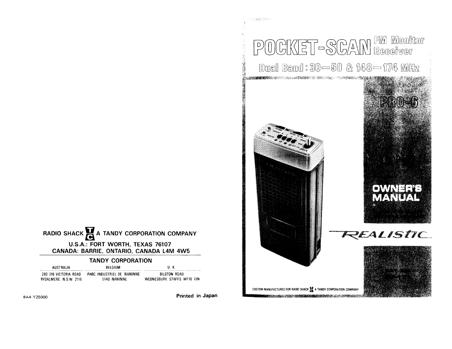
Pocket-Scan PRO-6 Scanning Receiver is a super
compact solid-state Dual-Band VH F, dual-conversion super-
heterodyne receiver, capable of
automatically
scanning 4 crystal
controlled
channels. Some special features are:
two
ceramic filters,
channel loek-out circuit, skipper
circuit
and EXTernal DC POWER
jack
for
operation
from
an external souree
of
6-volts DC. The
Pocket-Scan is intended to be used
by
Civil Defense personnel,
professional or part
time
public
servants (police, firemen, etc.). or
just
anyone interested in listening to the exciting action constantly
taking place on the air waves in
your
locality.
It is designed
for
use in the narrow-band FM channels
of
Public
Service communications:
VHF
band Police, Fire, Civil Defense,
Radio Telephone, Forestry and weather service, plus many
other
Industrial Radio Services. These and
many
other
services share this
band
of
frequencies
from
30
to
50
MHz
and 148
to
174 MHz.
The PRO-6 features
both
high sensrnvrtv and selectivity and a
sophisticated
circuit
which includes 10.7 MHz and 445
kHz
ceramic
filters to reduce or eliminate adjacent channel or strong -signaI
interference. Such interference is
often
experienced when operating
in urban and
metropolitan
areas
or where very strong and closelv
placed signals are present.
The PRO-6 represents some rather complex engineering and
manufacturing achievements,
but
is designed
for
very practical
applications.
And
still,
it
is remarkably easy to use.
It
can be placed
in
your
pocket, c1ipped to
your
belt, or operated in
your
home,
office
or vehicle.
You'lI
be amazed to realize
that
this small package
contains densely packaged
circuitry
composed
of
27 transistors,
two
integrated circuits (which incorporate the equivalent
of
hundreds
of
components), 17 diodes and 4
Light
Emitting
Diodes (LED's)
for
the scanning indicators.
Your
local Radio Shack store has a complete line
of
accessories
for
use
with
the
PRO-6-extra
batteries,
power
adapters, cables. crvstals,
antennas, etc.
-1-

SPECIFICATIONS
GUARANTEE:
The
RADIO
SHACK guarantee is stated on the
Guarantee card packed
with
the unit.
It
is in effect
from
coast-to-coast.
At
any time,
RADIO
SHACK equipment can be
restored to like-new
condition
with
original parts,
with
minimum
delay, anywhere in the U.S.A., normally right in
your
own
neighborhood. In 98% of the
cases,
it is
not
necessary
to return
RADIO
SHACK equipment to our laboratories.
WARNING
The PRO-6 is designed to operate
from
four
penlight
(AA)
batteries (connected in series), or an external souree of +6
volts DC (negative ground).
If
it
fails to operate, and there is
no
c1ear
reason
for
the failure, first check the batteries.
Before you
try
connecting the PRO-6 receiver to an external
6-volt DC power supply, check the voltage polarity.
Attempt-
ing to operate the negative ground PRO-6
from
aPOSITIVE
GROUND electrical system, may damage it. The Radio Shack
warranty does
not
apply to any damage
caused
by improper
power connections or
other
damage
caused
by misuse, damage
or neglect.
CHANNELS
OF
OPERATION:
FREOUENCY
RANGE:
FREOUENCY COVERAGE:
SENSITIVITY:
SELECTIVITY:
MODULATION
ACCEPTANCE:
IF. FREOUENCY:
FILTER:
SOUELCH
SENSITIVITY:
SCANNING SPEED:
DELAY
TIME:
AUDIO
POWER:
POWER REOUIREMENTS:
SEMICONDUCTOR
COMPLEMENT:
SPEAKER:
ANTENNA:
CRYSTAL
REOUIREMENTS:
Four-as
determined by any one of
4crystals operating in the frequen-
cy range
30 to 50 MHz and 148 - 174 MHz
(Lo) 6 MHz
for
maximum sensitivi-
ty
(40 MHz ±3 MHz)
(Hi) 8 MHz
for
maximum sensitivi-
ty
(153 MHz ±4 MHz)
Better than 1
microvolt
for
20 dB
quieting
±13.5 kHz, -6 dB
±20 kHz, -50 dB
±7 kHz
10.7 MHz and 455 kHz
10.7 MHz and 455 kHz Ceramic
Filters
Variabie
from
less
than 1
microvolt
6 channels/second
0.7 to 1.5 seconds
150
milliwatts
+6 volts DC (negative ground
only)
Current drain: 40 to 100
mA
(no
signal/squelched, to
full
volume)
2Integrated Circuits
27 SiliconTransistors
17 Diodes
4
Light
Emitting Diodes (LED's)
2",
16 ohm, Permanent Magnet,
dynamic type
Built-in wire loop, plus external
whip-type wire
Standard HC-25/u 3rd overtone
-2-
-3-

PREPARING
fOR
USE
To use
your
POCKET-SCAN, you must do
two
things:
Install the batteries
Install 1, 2, 3 or 4 crysta Is
To install the batteries;
turn
the receiver face
down
and press in
firmly
on
both
sides
of
the receiver at the place marked
BATTERY
PACK and
lift
the
compartment
up and away.
Remove the battery pack. Insert
four
AA
batteries, one at a time
making sure the
polarity
markings inside the battery pack match up
(+ to +and - to
-)
with
markings on the batteries.
We recommend Nickel Cadmium
AA
batteries, Radio Shack Catalog
Number 23-125, or
AA
NOVA
CELL,
Catalog Number 23-453 be
used in
your
new Receiver.
Crystals are
not
included
with
your
POCKET-SCAN
because the
frequencies are so numerous. The frequencies used in
your
part
of
the
country
will
be
different
from
those used in
other
areas.
Your
Radio Shack Store Manager
will
advise
you
as to
what
frequencies
are most used and help you in
your
selection
of
crystals.
Remove the Crystal Compartment Cover by sliding
it
to the
left
and
insert crystal
into
the crystal socketlLo
or
HO. Provision is made to
install 4crystals; each position can be used
for
either
VHF
Hi or
VH F Lo.
Follow
the
illustration
provided
for
proper installation
of
each crystal.
For
VHF
Lo crystals, use the center and lower crystal socket
holes.
For VH F Hi crystals, use the center and upper crystal socket holes.
In the example shown, Channel 1
will
have a
VHF
Lo crystal and
Channel 4
will
have a
VHF
Hi crystal.
CRYSTAL
COMPARTMENT
COVER
Since crystal frequencies must be
extremely
accurate and crystals
should be matched
for
specific units, we recommended you
obtain crystals
for
your
POCKET-SCAN
only
from
Radio Shack.
Be sure to specify the Catalog Number and Model description
of
your
Monitor
Receiver. We can
not
be responsible
for
the
poor
or
improper
operation
of
crystals
from
another manufacturer(s).
Press
the Battery Pack
into
place (press sides of Battery Pack in
ward to snap it back
onto
the case).
BATTERY
PACK
CRYSTAL
SOCKETS
SPEAKER SIDE
-4- -5-

JACK
BATTERY
COMPARTMENT
CONTROL
LOCATION
AND
FUNCTION
OFF-VOL
is the
power
switch
and
Volume
control.
When
not
in
use,
rotate
this
control
to
the
left
to
turn
it
off.
SQUELCH
control
is
to
eliminate
annoying background noise
between signal transmissions. When
properly
set, Squelch
will
keep
the PRO-6 silent
until
a signal comes in on the channelts)
you
are
listening
to-then,
the Squelch
circuit
will
"open"
and
you
hear the
signaI.
Selector
Switch
is
for
determining
the
function
of
the
scanning
feature. In the SCAN
position,
each channel
will
be scanned
automatically.
In the center (stop)
position,
the PRO-6
will
not
scan,
but
will
remain
tuned
to
the channel indicated by the
LED.
To advance the receiver
to
the
next
channel in sequence, press
to
the
MANUAL
position
momentarily;
each
time
you
do so, the
receiver
will
advance one channel.
CRYSTAL
COMPARTMEN\
meo~
RECHARGE /
POWER JACK
LED
CHANNEL
INDICATOR
BELT CLIP
Crystal
Compartment
contains crystals selected
for
operation.
EXTern
al Power and
Battery
Charge
Jack-
The
EXT
POWER
JACK
is
for
connecting an external souree
of
6volts DC (negative
ground),
so that
operation
without
the use
of
batteries is possible.
Channel
Loek-out
Switches-in
the
"up"
position
(button
next
to
the
LED),
that
channel is active. When
you
press the switch
down,
that
channel is
automatically
"locked
out"
and
will
not
function.
LED
Channel
Indicator-these
Light
Emitting
Diodes show
which
channelts) is active.
During
scanning, these lights
light
up in
sequence; when the receiver is operative on one of the channels, the
light
for
that
channel
will
go on. When the Channel
Lock-out
switch
for
that
channel is in the
down
position,
that
LED
will
not
light.
EARphone
jack is
for
plugging in the earphone. Use
it
for
private
listening or in areas where background noise is excessive (in
factorles. at the scene
of
an accident or
fire,
in a vehicle, etc.).
SELECTOR SWITCH
SCAN/STOP/MANUAL
---t-
CHANNEL
LOCK·OUT
sw.
ec--+----
EARPHONE JACK
POWERlVOL.
CONTROL
SQUELCH
CONTROL
ANTenna
jack
is
for
connecting an external antenna
to
the PRO-6.
You
can use
either
the
wire
antenna provided or an outside
VHF
antenna.
Belt
Clip
is provided so
you
can attach
the
PRO-6 to
your
belt
or
other
conven
ient
place.
Battery
Compartment
holds internal
power
souree (4
type
AA
batteries).
-6-
NOTE
The
RECHARGE
POWER
JACK
is
to
be used
only
when
Nickel Cadmium batteries are installed in
the
receiver.
To
recharge Nickel Cadmium batteries in the receiver,
simply
plug
an external
6-volt
DC
power
souree
into
the
RECHARGE
POWER
JACK.
-7-

OPERATION
Af
ter
batteries and a crystal (or crvstals) has been instalied,
your
PRO-6 is ready
to
use.
Turn
VOLUME
"on"
by
rotating
to
the
right.
Rotate
SQUELCH
to
the
minimum
position
by
rotating
to
the
left.
Set all the Channel
Loek-out
Switches
"on"
(in the up
position,
toward
the
LED
indicators).
You
should hear a rushing sound
from
the speaker.
Now
adjust
SQUELCH
to
the
right
until
you
reach the
point
where the
rushing background noise
abruptly
stops.
If
you
want
the PRO-6
to
continuously
scan the channels
for
which
you
have crystals installed,
you
must adjust
SQUELCH
as previously
instructed, then set the Selector
Switch
to
the
SCAN
position.
The
PRO-6
will
constantly
scan each channel in sequence; when a signal
appears on one
of
the channels the receiver
will
lock
onto
that
channel and
you
wi
11
hear the signa!.
If
you
do
not
want
automatic
scanning on one or more channels,
switch
their
Channel
Lock-out
Switches
to
the
"off"
position
(down
or away
from
the
LED
indicator).
If
you
want
to
stay
tuned
to
one channel
only,
set
the
Selector
Switch
to
the center
position
(stop scanning) and then press
to
the
MANUAL
position
to
advance to the channel
you
want
to
listen
to
(as indicated by
the
LED
above
that
channel switch).
For
MANUAL
scanning, the receiver can be
either
"squelched"
(adjusted as
previously indicated) or
"unsquelched"
(SQUELCH
control
set
to
extreme
left).
For
AUTOMATIC
scanning,
SQUELCH
must
be set
to
eliminate
the
background noise.
The PRO-6 has a
built-in
loop
antenna and in high level signal areas
you
may
not
need another antenna. However, in most
cases,
you
will
want
to
use
the
wire antenna
provided;
just
plug
it
into
the
ANTenna
Jack and
extend
the antenna
vertically.
For
the very best
reception,
you
will
want
to use an outside antenna-see the
ANTENNAS
section.
ANTENNAS
For
superior reception,
you
will
want
to
use an external antenna
such as Radio Shack Catalog
Number
20-015.
This
antenna is
designed
for
base station operation.
If
you
intend
to
use
your
POCKET-SCAN in a vehicle, we recommend Catalog
Number
20-016.
You
will
need coaxial cable
to
eenneet between the base
station antenna and the
POCKET-SCAN-use
Catalog
Number
278-970
(50
feet of
RG-8/U).
At
the
POCKET-SCAN, use a
sub-miniature phone plug on the end
of
the
coax cable (274-289)
or
a
combination
of
adapters
which
will
mate
into
a male sub-
miniature
plug.
For
mobile
use,
you
can
mount
the POCKET-SCAN
permanently
or
temporarily.
In
either
case, be sure
it
is positioned (along
with
its
cables) in a safe and convenient
location.
When
you
mount
a
mobile
anten na, keep
the
following
points
in
mind:
1. Mou
nt
the antenna as high as
possible-the
center
of
the
roof
is
best.
2.
It
should be rigid, so
it
will
be vertical when in
motion.
3. Keep
it
as far as possible
from
the engine
compartment
(the
engine is a souree
of
noise,
which
will
interfere
with
reception),
To
eliminate
the annoying background noise, rotate
SQUELCH
toward
the
right
until
the
background noise
abruptly
stops.
You
can't
adjust
SQUELCH
properly
while
listening to a
station,
so
wait
until
signals
cease.
If
you
set
SQUELCH
as
noted
above, the PRO-6
will
appear
"dead"
until
a signal comes in; when a signal comes in,
the
Squelch
circuit
"opens
up"
and
you
hear the signa!. When
the
signal
ceases,
the Squelch
circuit
"doses"
and cuts
out
all sound
until
the
next
signal comes in.
-8-
DUAL
BAND
VHF
Cowl
Mount
For
mobile.
Chrome
tele-
scopic
whip.
Swivel base.
Center-Ioaded
weatherproof
coil,
With
5'
RG-58/U
cabie.
Pin-plug
connector.
Catalog
Number
20-016.
-9-
DUAL
BAND
VHF
Ground
Plane
Heavy-duw
aluminum
ele-
ments.
Match
ing trans-
former.
Mounting
bracket.
Accepts
PL-259 con
nector.
Catalog
Number:
20-015.

FREQUENCY COVERAGE
For
maximum
sensitivity,
the channel frequencies
you
choose
should be
within
3
MHz
of
40
MHz
on the LO
VHF
band
(that
is,
in the spread
of
37
to
43 MHz).
For
the Hl
VHF
band, stay
within
4
MHz
of
153
MHz
(that
is, 149
to
157 MHz).
This
Receiver
will
function
very adequately
down
to 30 and up
to
50 and
from
148
to
175
MHz,
but
with
reduced sensitivity. The superior reception
spread
of
6 or 8 MHz
(±3/4
MHz)
can be moved up or
down
in
this
band
of
frequencies by special realignment
of
the
front
end
circuitry
of
this
Receiver (which should be
attempted
only
be
qualified
Electronics Service Technicians
who
have adequately calibrated,
precision test equiprnent).
With
such realignment,
your
Receiver can tune signals in the Ham
bands and
other
services. We call
your
attention
to the fact
that
this
Receiver is designed
for
reception
of
FM signals and
thus
can
not
be
used
for
monitoring
AM signals (even though
they
may be
within
the frequency coverage range). These AM signals include much
of
the
aircraft
services.
TYPES OF SIGNALS YOU'LL BE ABLE TO MONITOR
Your
community
is alive
with
action-action
which
is
constantly
being reported on the air waves.
And
your
PRO-6
will
automatically
scan the air waves
to
bring
you
that
action-your
police force at
work,
a
fire
truck
on a mission, Ham Radio operators,
highway
and
other
emergency-type services, some industrial services, some trans-
portation
services
(taxi,
trucks, railroad), plus some
Government
services. Lots
of
things are going on
that
most
of
us
just
are never
aware
of.
But,
with
the
right
frequency crystal in
your
PRO-6
you
can
monitor
such
exciting
signais.
You'll
have to do a
Iittle
investigating in
your
community
to
find
out
what
services are active
and on wh at frequencies.
You
will
find
one
of
our
books
to
be very
interesting and
helpful
in this area:
REALISTIC
GUlDE
TO
POLICE,
FIRE
AND
AIRCRAFT
RADIO.
What
to
listen
for
and where?
That
is a
little
difficult
for
aspecific
answer. Each area of the
country
can and
will
use
different
frequencies.
All
we can
do
is give
you
some general
pointers
and let
you
take
it
from
there.
-10
-
Find
out
if
there is a local
club
which
monitors
these frequencies.
Often
alocal
electronics repair shop
that
does
work
on the
equipment
can give
you
the channel frequencies used by local radio
services. A
volunteer
police or
fire
employee can also be a good
souree
of
this
information.
An interesting service is the
Mobile
Telephone. FCC has assigned
th is service channels in
the
range
of
152.51 to 152.81 MHz at every
0.030
MHz
(channels are 30
kHz
apart).
As a general rule on
VHF,
most
activity
will
be concentrated
between
153.785
and
155.98
and then again
from
158.73
to
159.46
MHz. Here
you'lI
find
local government, police,
fire
and
most
such
emergency services.
If
you
are near a railroad yard or
major
railroad
tracks,
look
around
160.0
to
161.9
MHz
for
them.
NATIONAL WEATHER SERVICE RECEPTION
Continuous
weather broadcasts are
transmitted
24-hours-a-day in
many
parts
of
the
country.
If
you
are using a crystal set
to
on~
of
the
two
channels assigned
(162.55
or
162.40
MHz),
your
Receiver
will
automatically
loek-in on
that
channel, since the broadcasts are
continuous.
To
prevent
automatic
locking,
set the channel
loek-out
button
for
th
at channel to the
"off"
position
(button
out).
When
you
want
aweather report, set the
Loek-Out
Button
to the
"on"
position
(press in)
for
that
channel. In areas where
two
stations are
close to each
other,
one
will
use
162.55
and the
other
will
use
162.40
MHz. Check
with
your
local FCC
office
or the Weather
Bureau
for
the
frequency used in
your
area.
ACCESSORIES
Your
PRO-6 can be powered
from
any souree
of
6
volts
DC,
negative ground. Using an AC adapter
will
save on batteries; so,
if
you
intend
to
use the PRO-6 in
alocation
where 120 volts is readily
available, and
it
does
not
need to be moved around, consider an
adapter. Radio Shack has
two
power
adapters
which
you
might
be
interested in. Catalog
Number
270-1531 is a universal adapter
for
120
volts
AC,
to
provide
4.5/617.5/9
volts
DC (positive or
negative). Catalog
Number
270-1532 is a
power
adapter
for
plugging
- 11 -

into
acigarette lighter socket in
your
vehicle and providing either 6
or 9 volts DC (positive or negativel. This
will
permit
you
to use the
PRO-6 in
your
car or
truck
without
wearing
down
your
batteries.
Of
course,
with
such an adapter you can recharge Nickel Cadmium
batteries by using the RECHARGE POWER
JACK.
MAINTENANCE
The PRO-6 is a ruggedly
built
electronie
unit,
with
all parts
conservatively rated. However, you should treat
it
with
care;
don't
subject
it
to excessively rough handling. You
will
find
it
will
give
you long life
if
kept
free
from
dirt
and excessive
humidity.
If the sound becomes weak and distorted, it is
time
for
new
batteries. We recommend Radio Shack
Alkaline
batteries, Catalog
Number 23-552. Or, use
our
ENERCELL
rechargeable batteries
(23-125)-you
can recharge them hundreds
of
times.
If
vou
do
not
intend to use the PRO-6
for
a few weeks,
it
is best to remove the
batteries. Also, never leave weak or dead batteries in the
unit.
BLoeK
DIAGRAM
-12-
::E
ce
D::
~
ce
-
c
o
-
I-
ce
::E
w
z
o
(/)
~------
- -
---------
- - -
---1
, I
,/I~I~lC
I
I
I
I
I
I
I
I
I
-13-
,~
t

SCHEMATIC
DIAGRAM
J2
EARPHONE
r-_--.:
.....
'"
JACK
J3
EXT.POWER
JACK
6V DC
J4
"'~r
CHARGE
JACK
CD,...
~N
----------------------
/
S6 /
~~IES
~
u~,
6V
,<,
~
"
:g I
'" I
I
I
I
I
I
0142SC735(V)
REMARKS:
1. RESISTANCE
VALUES
IN OHMS
IK"10001IM=10000001
2. CAPACITANCE
VALUES
IN MF
IP"MMFI
3. (TI
TANTALUM
CAPACITOR
4. (MI
MYLAR
CAPACITOR
5.
ALL
VALUES
AND
RATINGS
ARE SUBJECT TO CHANGE FOR
IMPROVEMENT
WITHOUT
NOTICE
FUNCTION
.n.
ANTENNA
JACK
J2, EARPHONE JACK
J3:
EXTERNAL
POWER JACK
J4: CHARGE JACK
Sl - 4:
CHANNEL
SELECTOR SWITCH
S5:
AUTO/MANUAL
SWITCH
S6: POWER SWITCH
REMARKS:
C,->THIS
SYMBOL
INDICATES
DC
VOLTAGE
MEASURED
BY V.T.V.M. AT THE
CONDITiON
OF
HIGH BAND CH·l
MANUAL
OPERATED:
VOLUME
MINIMUM
POSITiON AND SQ. CONToOUT POSITION.
08-
13 2SC373
01-72SC372(Oi
019
2SC373
018
2SC784 (0)
D5-12
HV80
"- R38 100
IC<!
I~
1-'
016,17
2SC394 (V)
4Qi:2
ç6P
.5
R5 lOOK
:
~~
:~C1347P
I
~t'""
I
uu
0.6
CRVSTAL
SOCKET
~--"""+-"f-'-i-o-
"fo'-+:
-+-
D9
-+-io
...........
"
..
'---1---
':
~
~:c::
a::~~
~~i~
~*~
~c::
...
---
........
-..
..-+-+-+-------'
I
I
01-42SC784(0)
"çj
L
~
VHF
HI/LO
FRONT
END
1-----------~6---~---l
~~T.JACK'
T.~o;~r
C440pR.ll00K
~
"
:TG5T:~06
I
I
~
w
I
Table of contents
Other Tandy Receiver manuals