5
TapcoTools.com 800.521.8486
Pivot Link Adjustment Instructions
IMPORTANT: Your Port-O-Bender
®
incorporates an advanced new Micro-Adjust system that enables you to adjust the gripping
tension on material faster and easier than ever. The Pivot Links have been pre-set at the factory for average holding capacity
and ease of operation. However, it’s important that you readjust your Port-O-Bender
®
to your stock thickness.Your Port-O-
Bender
®
may also need periodic adjustment due to extreme weather and/or working conditions. It is important that you follow
these steps when you adjust your Port-O-Bender
®
to ensure proper gripping tension and maximum performance.
First check the uniformity of the clamping pressure along the entire length of
your Port-O-Bender
®
by using the following method.
TO TEST —
Cut some narrow strips of aluminum or use strips from the stock you will be using
and lock one under each shoe casting as indicated in Figure 1. Then lightly pull
the material to determine the tightness and uniformity of each Pivot Link. Refer
again to Figure 1. If the material can be moved when the Port-O-Bender
®
handle is
locked or if it requires excessive pressure to lock the handle down on the material
then the Pivot Links may need adjustment.
NOTE: All adjustments are made with the Port-O-Bender
®
in the “open”
position. All adjustments are tested with strips of material placed in the
Port-O-Bender
®
in the “locked” position.
Figure 1
TO ADJUST (Optional method)—
As an alternate method you may use a 5/8" open-end wrench
directly on the Pivot Link Stud by turning 1/4 turn either
COUNTER-CLOCKWISE to INCREASE locking tension or
CLOCKWISE to DECREASE locking tension. (See Figure 3.)
Repeat test step above to check tension.
TO ADJUST —
Insert the 3/16" hex wrench provided into the Pivot Link Stud through
the access hole in the upper link. (See Figure 2.) Turn 1/4 turn
either COUNTER-CLOCKWISE to INCREASE locking tension
or CLOCKWISE to DECREASE locking tension.
Repeat test step above to check tension.
Figure 2
Figure 3
Pivot Link
Stud
Upper
Adjustment
Link
Lower
Adjustment
Link
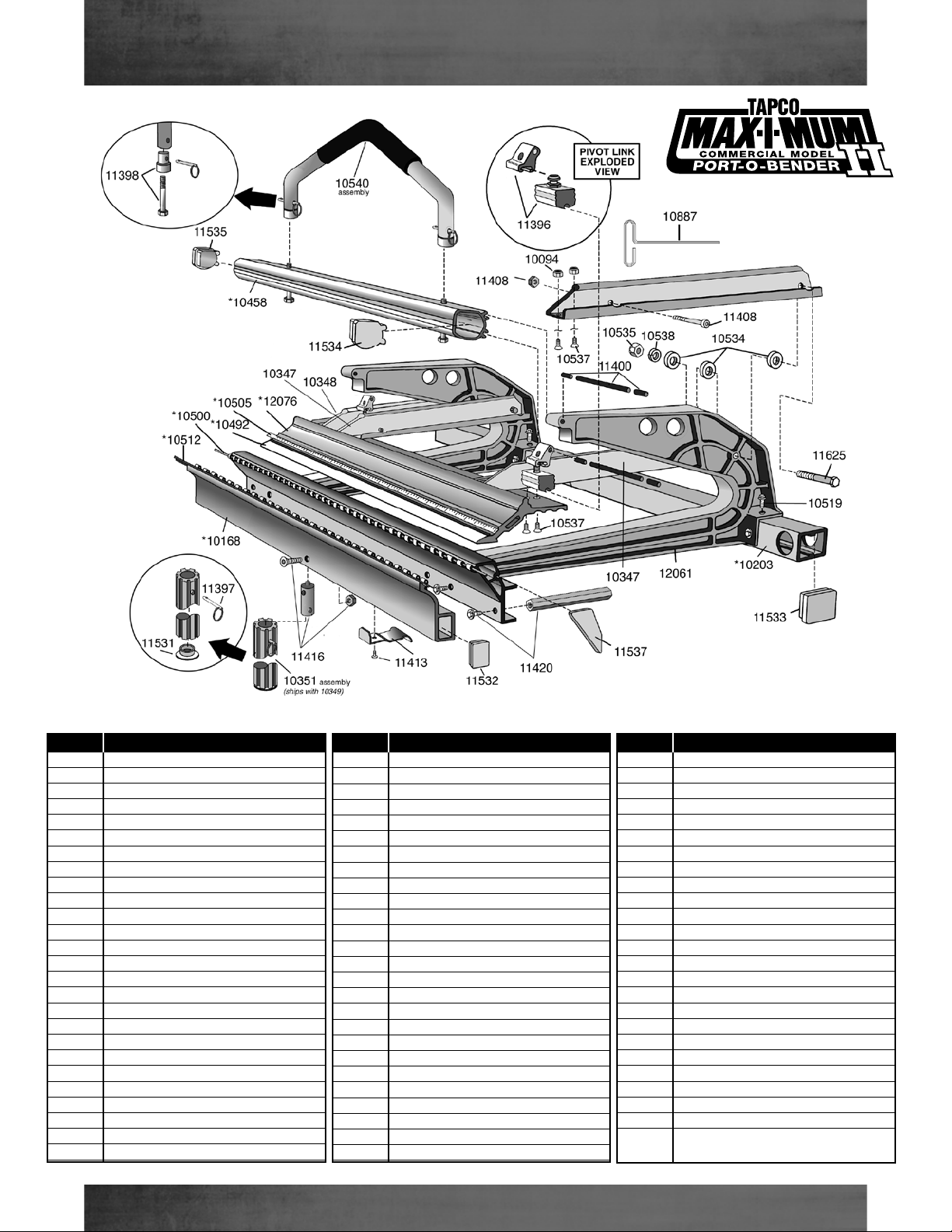
MAX-I-MUM II
Port-O-Bender Pivot Link Assembly
Adjusting the MAXIMUM II Port-O-Bender®
Decrease
Increase