TAPCO TOOLS MAX-I-MUM XL User manual

MAX-I-MUM XL
Commercial Bender System
The MAXIMUM XL COMMERCIAL
BENDER SYSTEM includes:
MAX-I-MUM II™Port-O-Bender®
MAX Snap Stand®andWheel Kit
Adjustable MAX Cut-O™
Table of Contents
MAX-I-Mum II
Setup.......................................................................... 1
Adjustment.............................................................. 2
Parts List.................................................................... 3
Care & Maintenance ............................................. 4
Specifications.......................................................... 4
Examples of Basic Shapes................................... 5
Adjustable MAX Cut-Off
Setup.......................................................................... 6
Parts List.................................................................... 6
MAX Snap Stand
Setup.......................................................................... 7
Wheel Kit................................................................... 7
Installing MAX Brake............................................. 8
Counter Balance Assembly ................................ 9
Removing MAX Brake.........................................10
Parts List..................................................................10
TapcoTools.com | (800) 521-8486
Operations Manual

3
TapcoTools.com 800.521.8486
1
Hinge Clip Installation
The Hinge Clip keeps the Moving Hinge in position for ease of aligning
material. It can also prevent rippling of the material during cut o operations.
To install Hinge Clip, locate predrilled hole on bottom center of Moving Hinge.
Align holes in Clip and Hinge as shown and insert Phillips head screw provided.
Note: You must engage Hinge Clip for proper operation of the Adjustable MAX
Cut-O.
Faspin
Locking Handle
Handle
Plug
Hemming
Handle
Hex Bolt
Hemming Handle Installation
The MAXIMUM II Hemming Handle
Assembly (10' 6"
& 12' 6" Brake) includes: (2) Hemming Handles, (4) Handle
Plugs, (4) Faspins, (4) Hex Bolts. The 8' 6" Brake includes:
(1) Hemming Handle, (2) Handle Plugs, (2) Faspins, (2) Hex
Bolts. The 14' 6" Brake includes: (3) Hemming Handles, (6)
Handle Plugs, (6) Faspins, (6) Hex Bolts.
Attach the Hemming Handle over the Handle Plugs and
secure them with Faspins. Now tighten the 3/8" Hex Bolts
with a 9/16" wrench. Handle can be detached from now on
by simply removing the Faspins.
T-Handle
Wrench
Exploded view of Handle Assembly —
First insert one end of
Handle Plug into Lifting/Bending Handle and install Faspin
through holes.
Next, insert Handle Assembly into hole in bottom of
Moving Hinge. Align hole in hinge with Handle Plug and
insert screw using Allen wrench as shown. Secure with
1/4-20 Lock Nut.
Lifting/Bending Handle Installation
Repeat for other handles.To remove handles now, simply
release Faspins. Always use more than one handle when
bending.
Insert Hex Bolt through Locking Handle of your Port -O-
Bender and into base of Hemming Handle as indicated
using the 3/8" Hex Bolts provided. HAND TIGHTEN ONLY.
Repeat for other side.
Faspin
Handle
Plug
1/4-20
Lock Nut
Lifting/
Bending
Handle
Moving
Hinge
1/4-20 x 11/2" Screw
Secure
with 1/4-20
Lock Nut
Setting up your MAX-I-MUM II

4
TapcoTools.com 800.521.8486
2
Adjusting your MAX-I-MUM II
IMPORTANT: The Power Links on yourTapco Brake have been pre-set at the factory for average holding capacity and ease
of operation. However, the Power Link Stud allows you to adjust the brake to your specic bending needs. It is important that you follow these steps when you adjust
your Brake to ensure proper gripping tension and maximum performance.
CAUTION: overtightening the Link Stud can result in damage to brake components.
First check the uniformity of the clamping pressure along the entire length of yourTapco Brake by using the following method.
Decrease
Increase
Power Link Adjustment Instructions
TO TEST
Cut some narrow strips, approximately 2" x 4", of aluminum or use strips from stock you will be
using and lock one under each shoe casting as indicated in Figure 1. Lightly pull the material
in a side to side and outward motion to determine the tightness and uniformity of each Power
Link. Refer again to Figure 1. If the material can be moved when the handle is locked or if it
requires excessive pressure to lock the handle down on the material then the Power Link may
need adjustment.
NOTE: All adjustments are made with the Tapco Brake in the“open”position. All adjustments
are tested with strips of material placed in
the Brake in the“locked”position.
TO ADJUST
1. Insert the ³⁄16" hex wrench into the Power Link Stud (See Figure 2.)
2. Turn a ¼ to ½ turn either CLOCKWISE to INCREASE locking tension
or COUNTER-CLOCKWISE to DECREASE locking tension.
3. Adjust each shoe casting until all are uniform.
Repeat test step above to check tension.
Power Link Stud
Figure 1
Figure 2

5
TapcoTools.com 800.521.8486
3
MAX-I-Mum II Parts List
Item # Description
10094 1/4 -20 Hex Flange Nut
12625 8'6" Max Moving Hinge
12626 10'6" Max Moving Hinge
12627 12'6" Max Moving Hinge
12628 14'6" Max Moving Hinge
12621 8'6" Max Fixed Hinge
12622 10'6" Max Fixed Hinge
12623 12'6" Max Fixed Hinge
12624 14'6" Max Fixed Hinge
10201 8'6" Max Back Rail
10203 10'6" Max Back Rail
10205 12'6" Max Back Rail
10207 14'6" Max Back Rail
10347 Max/Pro 19 Left Pivot Arm
10348 Max/Pro 19 Right Pivot Arm
10351 Lifting Handle Assembly
10454
HD Pro/Max 8'6" Locking Handle
10458 HD Pro/Max 10'6" Locking Handle
10462 HD Pro/Max 12'6" Locking Handle
10464 Max 14'6" Locking Handle
10491 8'6" Stainless Edge
10492 10'6" Stainless Edge
10493 12'6" Stainless Edge
Item # Description
10494 14'6" Stainless Edge
10499 8'6" Hinge Pin
10500 10'6" Hinge Pin
10501 12'6" Hinge Pin
10502 14'6" Hinge Pin
10504 12'6" Tape Measure
10505 10'6" Tape Measure
10506 8'6" Tape Measure
12369 14'6" Tape Measure
10511 8'6" Vinyl Strip
10512 10'6" Vinyl Strip
10513 12'6" Vinyl Strip
10514 14'6" Vinyl Strip
10519 1/4 -20 x 3/4" Hex Wash HD Screw
10534 3/8" Flat Washer
10535 3/8-16 Nylock Hex Nut
10536 3/8-16 X 2 1/4 HEX BOLT
10538 3/8" Lock Washer
10540 Hemming Handle Assembly
10887 T-Handle Hex Key
11332 Screw 1/4-20 x 7/8" Flat HD
14963 Power Link Kit
11397 1/4" x 1-1/4" Faspin Kit (4)
Item # Description
11398 Hemming Handle Plug Kit
11400 Locking Handle Pin Kit
11408 Bolt and Nut Kit
11413 Hinge Clip Kit
11416 Max Handle Plug Kit
11420 Coupling Nut Kit
11531 Lifting Handle Cap
11532 Moving Hinge Cap
11533 Back Rail Cap
14274 Locking Bar Cap
11536 Left Base Hinge Cap
11537 Right Base Hinge Cap
11625 3/8-16 3-1/4" Hex Cap Bolt
12042 10'/12' MaxII Parts Bag
12055 8' MaxII Parts Bag
12056 14' MaxII Parts Bag
12061 Pro 19/Max C Casting
12075 8'6" Max Locking Anvil
12076 10'6" Max Locking Anvil
12077 12'6" Max Locking Anvil
12078 14'6" Max Locking Anvil
*Note: For length-specic parts, 10'6" parts numbers are shown in diagram.

6
TapcoTools.com 800.521.8486
4
For Your Records
Complete the information below and
save for future reference.
Model and Serial Number
Date and Place Purchased
LENGTH WORKINGWEIGHT
ITEM # PRODUCT Feet Meters Pounds Kilograms CAPACITIES
11017 MAX-I-MUM XL Commercial Bender System 8' 6" 2,59 m 133 lbs. 60,1 kg
11018 MAX-I-MUM XL Commercial Bender System 10' 6" 3,20 m 158 lbs. 71,6 kg
11019 MAX-I-MUM XL Commercial Bender System 12' 6" 3,81 m 190 lbs. 86,0 kg
10997 MAX-I-MUM XL Commercial Bender System 14' 6" 4,42 m 217 lbs. 98,3 kg
12261 Adjustable MAX Cut-O with case – – 9 lbs. 4,1 kg
Aluminum: Up to .040
Galvanized steel: Up to 24 ga.
Soft & annealed copper: Up to 32 oz.
Stainless steel, ¼ hard: Up to 24 ga.
Specifications
Your Tapco Port-O-Bender®is virtually maintenance free and will provide you with years
of reliable and trouble-free performance. However, there are a few basic necessities
required to keep your Port-O-Bender®like new.
1. Clean the clamping surfaces each day before using. Use only clean shop towels that
are free of dirt, oil and metal chips.
2. Do not use your bender around your saw table as the cuttings may get in between
clamping surfaces and cause excessive wear or material scratching. Brush away any
cuttings or lings that accumulate.
3. Transport your Port-O-Bender®in the unlocked position.You may transport it in
the locked position if you clamp a piece of cardboard or vinyl siding between the
clamping surfaces.
4. If your material is getting scratched, examine the Stainless Bending Edge, Base
Hinge and Moving Hinge for roughness or burrs. Remove burrs with emery cloth or
replace excessively worn parts. Using the Adjustable MAX Cut-O will help eliminate
excessive wear to costly bending edge.
5. Use a lightweight spray oil along the moving pivot hinge after every 40 hours of use.
Care and Maintenance of MAX-I-Mum II

7
TapcoTools.com 800.521.8486
5
NOTE: UP and DOWN refers to the clad, painted or FINISH SIDE of the material as it is placed into the Bender.
1
2
7
4
5
3
6
6. Outside Corner
2. Coping Cover
1
2
3
5
4
7. Counter Flashing
3. One Piece Soffit Mitre 8. Brick Frieze
5. Hip/Ridge Cap
9. “F" Channel/Inside Corner
5
4
2
3
1
4. Reglet Flashing
10. “D" Style Gutter
1. Gravel Stop
3
2
4
5
1
Examples of BASIC Shapes

8
TapcoTools.com 800.521.8486
8
TapcoTools.com 800.521.8486
6
10013
10021
10227
12263
12264
ASSEMBLY
10227
ASSEMBLY
10020
10225
10015
11409
12396
10008
10021
12293
Adjustable
* This kit replaces the Track Bearing Kit 11393. Both are still available for purchase.
** Please contact Customer Service if these parts need to be replaced.
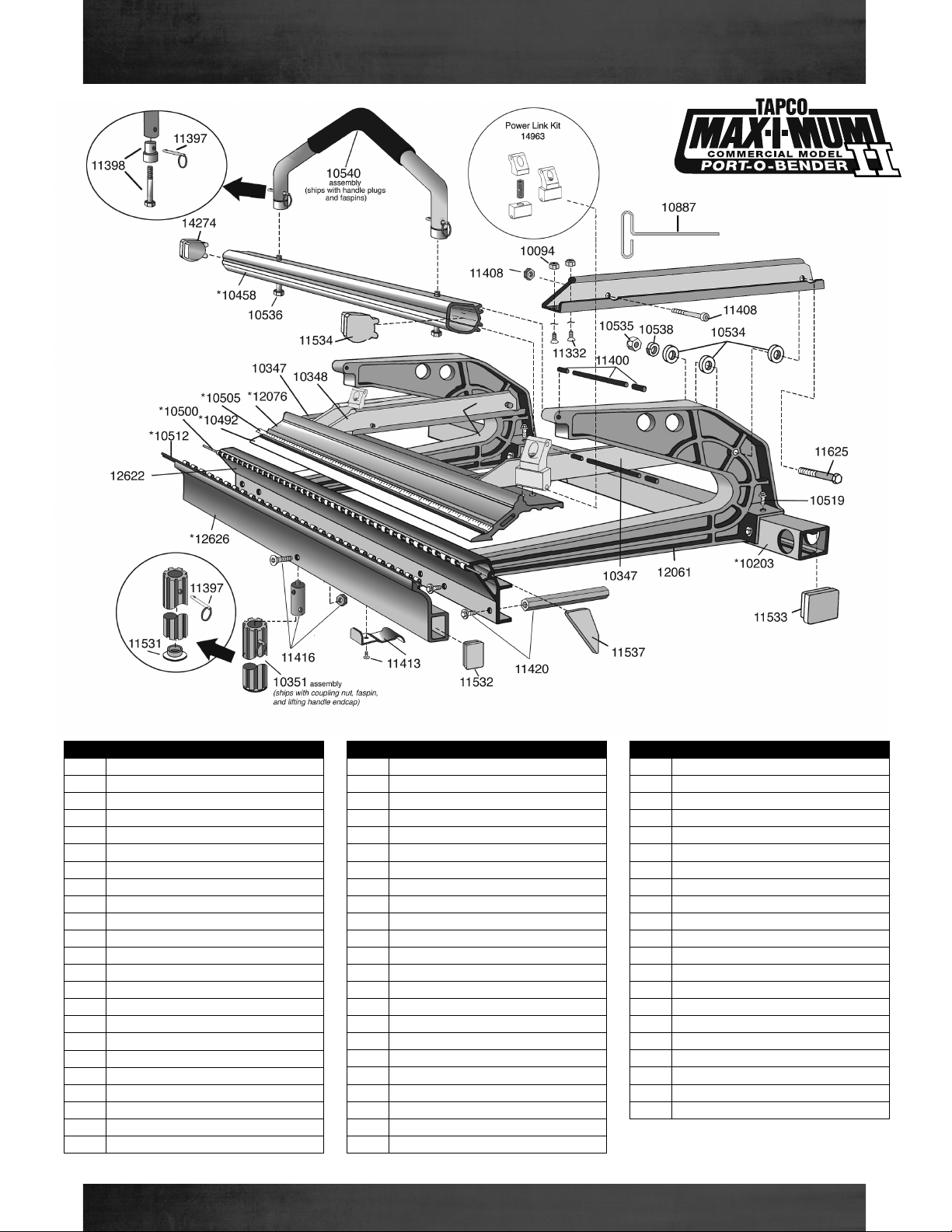
Item# Description
10225 Bridge
10008 Handle
12264 Adjustable MAX Cut-O Body
11409 Cut-O Guide Bearing Kit
(2) Guide Bearing 10016
(2) 5/16" Roll Pin 10015
12396 FlangeTrack Bearing Kit*
(2)Wide FlangeTrack Bearing 12334
(2) 1/4-20 x 5/8" Hex Button
Hd Screw 12364
11393 Track Bearing Kit (not shown)
(2)Track Bearing 10012
10021 1/4-20 x 1" Hex Button Hd Screw
10020 1/4-20 x 5/8" Hex Button HD Screw
10013 1/4-20 x 1-1/4" Button Hd Screw
10227 MAX Knife Assembly**
Knife (10226), Bearing (10231)
Nut (10232), .125 Shim
10349 Coupling Nut (hook, not shown)
10519 1/4-20 X 3/4" Hex Wash Hd Screw
(not shown)
11404 Material Stop Kit (not shown)
(2) Material Stop 10740
(2) 1/4-20 Knurled Knob 10776
(2) Cut-OTape Measure 10023
12263 Adjusting Nut
12293 1/4-20 X 1 1/2 Socket Head Cap Screws
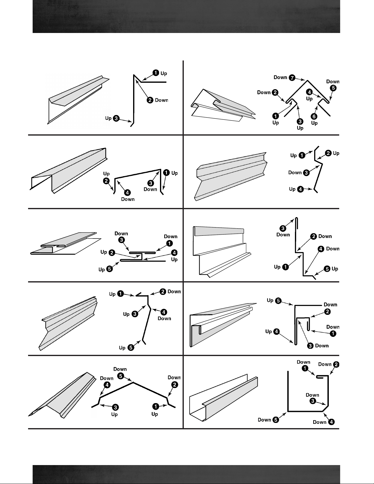
4 Secure the tape measures in place by“punching”
down the edge of the pivot arm onto the tape
measure. Use a standard nail set or punch.
IMPORTANT! Read this safety information
before using product.
1. Always keep hands and ngers clear of the knives
during all phases of use.
2. If using both hands to push tool through material,
ensure hands are not in the path of the exiting
material as it leaves the rear area of the tool.
3. Remove cut-o from anvil prior to bending
material. Failure to do so can cause the tool to fall
from brake resulting in tool damage or personal
injury to user.
4. Never use tool to cut material not rmly clamped
in brake.
LIST OF PARTS:
(1) Adjustable MAX Cut-O,
(2) Material Stop Kit #11404,
(2) Coupling Nut Kit #11420,
(1) Storage/Coupling Nut,
(1) Hinge Clip Kit #11413,
(1) 10-24 x 5/8" Phillips screw.
Tools Needed for Initial Set Up:
hammer, punch or nail set,
9/16" wrench, Phillips screw driver. 1 Disconnect the Hemming Handle from your Bender
by releasing the Faspins. This will allow the Bender to
fully open making it easier to slide Cut-O Stops onto
the Pivot Arms.
2 Slide material stop onto Pivot Arms from rear as
shown. Note: Recommended locations are on the
second castings in from each end of your bender.
3 Slide measuring tapes into Pivot Arm slots from rear of
Pivot Arm till they stop.Tape measures take into account
1½" dierence between the bending edge and the shear
point of Cut-O for accurate cuts.
Pivot Arm
Casting
IMPORTANT:
5" mark on tape
measure should
be inserted first.
Open Bender as wide
as possible.
Hemming
Handle
Faspin
Setup for Adjustable MAX Cut-Off and Parts

9
TapcoTools.com 800.521.8486
STEP 1
To open each Leg Set, push in on the snap button and move each leg
outward to the working position. Figure 1A above shows the leg set
as shipped while Figure 1B shows the leg set open (working position).
Make sure button snaps out to lock each leg.
STEP 2
Attach the Cross Braces to the Leg Sets.With the snap button of
the Leg Set pointing to the outside, snap the Cross Braces into
position. See Figures 2A and 2B above.
Be sure the C-shape of the Cross Brace is mating the leg as shown
in Figure 2C above. After the Cross Braces are Locked in place add
Spade Screws at each end. See Figure 2D above.
Figure 1A
Figure 1B
Figure 2A Figure 2B
Figure 2C
Snap Button locations when
legs are closed.
Snap Button locations
when legs are open.
STEP 1
Insert the wheel assembly into the leg of the Snap Stand as
shown in the gure above.Tap the bracket with a hammer to
wedge it tightly into the leg. Repeat this process for the other
leg.
STEP 2
To prohibit the stand from rolling on the wheels, lock the leg exten-
sions into one of the bottom two locking positions. See gure above.
If the leg extensions are in one of the other 3 positions, the wheels are
in contact with the ground and are free to roll.
STEP 3
To remove the wheel
assembly, tap the bracket
downward with a hammer
to disengage.
Use one of these posi-
tions to stop the stand
from rolling.
Attaching Wheel Kit (Optional)
Figure 2D
MAX Snap Stand and Wheel Kit Setup

10
TapcoTools.com 800.521.8486
STEP 1
Using the 1/4-20 bolts and lock washers provided, fasten the brake
mounts to the Leg Set.
STEP 2
The snap buttons will be toward the working
side of the brake. Repeat Step 1 for the other
Leg Set. Be sure both ends of the Snap Stand
are going the same direction (with the snap
buttons on the same side). See Figure 2 above.
snap buttons are
toward working
side of brake
STEP 3
Place the brake on the assembled Snap Stand
with the Back Rail of the brake clearing the
adaptor hook as shown in Figures 3A and 3B
above.
Back Rail clearing adaptor
hook
The snap button will be covered
by the xed hinge of the brake as
in Figure 3C above.
STEP 4
Push the brake rmly rearward into the adaptor
hooks.The snap buttons by the front clips will pop up
and secure the brake on the Snap Stand. See Figure 4
above. The brake is now ready for use.
Button pops up when brake is fully
seated
Figure 2
Figure 4
Figure 3A Figure 3B
Figure 3C
Figure 2
Snap Button is toward the work-
ing side of the brake
1/4-20 Bolt LockWasher
Installing a MAX Brake on MAX Snap Stand

11
TapcoTools.com 800.521.8486
Removal is the reverse of assembly. Lift up on the steps to release them from the legs, and slide the assembly
to the right until the connectors are free of the legs.
STEP 1
Attach the Connectors to the Steps using the carriage bolts, lock washer and nuts provided.The square portion of the carriage
bolt will fall into the square holes that are punched in the Connector.Tighten securely using a 7/16" wrench. See gure 5
above for Connector orientation.
Connector
STEP 2
To attach the Step Assembly to the Snap Stand, hold the assembly at an angle as shown and slide both connectors leftward over both legs
of the Snap Stand as far as they will go. Allow the connectors to slip down the legs until the steps are at and touching the ground. The con-
nectors should be gripping the front and back of each leg. Standing on the steps while bending will lock the connectors in place on the legs.
Step
TOP UNDERSIDE
Figure 5
Attaching the Counter Balance Assembly

12
TapcoTools.com 800.521.8486
Item # Description
10770 LockWasher
11990 Cross Brace Assembly
11996 Rubber Leg Cap
11997 Bronco End Plug
12111 Universal Adaptor Kit*
(2) 12120, (2) 12119, and (1) 12323
12123 Snap Button
12135 Top Channel
12132 Outer Side Plate
12172 Inner Side Plate
12170 Left Outer Leg Assembly
12173 Right Outer Leg Assembly
12169 Inner Leg Assembly
12120 Front Universal Adapto
12318 MAX Adaptor Bracket Assembly
12321 Counter Balance Step
12320 Counter Balance Step Connector
12322 MAX Snap Stand Parts Bag
MAX Snap Stand Parts List
1. Removing the brake from the Snap Stand is essentially the opposite of attaching it to the stand.
2. Lifting the Moving Hinge, depress the snap button and pull the brake forward far enough to hold
each snap button down.
3. Be sure the box rail is out of the Rear Clip. The brake can now be removed from the stand.
4. Reverse Steps 2 and 1 to disassemble the stand for transport.
10770
Spade Screw
Removing a Brake from MAX Snap Stand

Manufactured under one or more of the following U.S. Patents:
3,161,223 4,321,817 4,651,553 4,489,583 4,493,200 4,445,356
4,372,142 4,766,757 3,817,075 4,557,132 4,240,279 4,671,094
3,482,427 4,494,397 3,559,444
5,343,728 5,353,620 5,505,069 Other U.S. & Foreign Pats. Pend.
TapcoTools.com
800-521-8486
SIDING & ACCESSORIES
TRIM & MOULDINGS
ROOFING
STONE
WINDOWS
OUTDOOR LIVING
WestlakeRoyalBuildingProducts.com
© 2022 Westlake Royal Building Products
T30048341 2/22
Table of contents
Other TAPCO TOOLS Construction Equipment manuals