Tascam 3030 User manual

w
.€
=F-
( TASCAM
TEAC Professional Division
.,
il./e
W'qHftT
3'e k/D" 62ap
71 / o'.fu
d, 4lP*a4 a'/ ---?
-2,-a*e,':t' Zilz n firc-t'4*
SERr/ICE iAANU \L
-3030
Stereo Tape Deck
z
NOTES
As regards the resistors and capacitors, refer to the circuit
diagrams and the PCB ass'y drawings contained in this manual.
*
*
Parts marked with * require longer delivery time.
Resistor values are in ohms (k = 1,000 ohms, M = 1,000,000
ohms).
All capacitor values are in microfarads (p = picofarads).
A Parts marked with this sign are safety critical components.
They must always be replaced with identical components - refer
to the TEAC Parts List and ensure exact replacement.
0 dB is referenced to lV in this manual unless otherwise specifi-
ed.
PC boards shown viewed from foil side.
Parts not shown in the parts lists or parts, through listed, having
no parts numbers are not general "ready-to-supply" parts.
o dbx Noise Beduction system made under license from dbx,
lncorporated. The name'"dbx" and the dbx symbol are
trademarks of dbx, Incorporated.
rif,
i+-'+al&.+fi.'. =>7>+t- ct€n6 L < &> t) * ?" EE6tr
.&u*tEtr t +r,q L ( ( /: a t..
| . jt) > F EtFEti/rt ->ffihrjrr3fu(r'*-f.
2 . * EIla)Hlfr (Jftfr -pfihrE+h.h,,) *t " b 4 h' c b :J a
( /: d t'"
3 . AEIrtjteiEffi=E**15&('f" tt*{ 6 t 3 $'v't7 4
7 'v 2 ]?E.Jj=*fJff A1trH L (T 3 t."
4 . t/ ^)v(todB: tva4+t: L <t. * f"
5 . ) >7>to41il1rF.p:pr(l/F: 1,000,000pF)
6. ry&rr&=3 fl(r. 6f-&>t,. $lF"r EE6trr'-*[JE:
<r'6taeh:b() *t"
7 . U Z l- 6 11( L' A t'*ttF. (i/FF|J Z L < t - C z {^lita*Ef.
t L-cEt*8.-> ( r. * tl,"
odbxdijLidbx" ?{Sclbxl > r'-fi1' -'v fai,f.3*
ti,'ifii -d.
r dbr ) Z i A l* dbx { >: tf' ) -- r -.t t- O'ii Irfu tfi: la 1! I
t\ Cb!jn-*.1-t Ct\tT.
+\
Effective; March. 1989 930153 5704043400

1 SPECIFICATIONS AND SERVICE DATA
,lx&t.r-c7-7 -t
MECHANICAI CHARACTE BISTICS
Tape Format 2-lrack, 2-channel recording/
repr00uce
4-trak, 2-channel reproduce
Max. Reel Size 10-112" , NAB hub
Tape Speed 38 cm/s (15 ips) and lg cm/s
(7.5 ips)
Speed Accuracy !0.5 % deviation
Pitch Control 16 %
Wow and Flutter 10.07 % peak weighted
(DlN 45507)at l5 ips,
10.08 % peak weighted
(DlN 45507)at 7.5 ips
Fast Wind Time approx. 100 sec. for
1,800 ft.
Motors
Capstan FG servo DC motor
Reel 2 DC slotless motors
Head Conliguration 4 heads; 2-track
Z-channel erase, record, reproduce
and 4-track 2-channel reproduce
Dimensions 432 x 456 x 268 mm (17" x
11-5116" x l0-9/16")
Weight {net) 21 kg (46.5/16 lbs)
ETECTBICAT CHARACTERISTICS
Mic Input
Input lmpedance 10 kohms, balanced
Applicable Mic lmpedance 200 ohms or
m0re
Minimum Input Level -72 dBV
(0.25 mV)
Line Input Balanced/ Unbalanced
Input lmpedance -
I 0 koh ms/ 50 kohms
Maximum Source lmpedance
2 kohms/'10 kohms
Nominal Input Level
+4 dBm (1.23v|1-10 dBV {0.3 V}
Maximum Input Level
+28 dBm (t9.5 V)/ +18 dBV (8.0 V)
Line Output Balanced / U nbalanced
0utput lmpedanc,e
100 ohms/ 500 ohms
Minimum Load lmpedance
600 ohms/3 kohms
Nominal Load lmpedance
10 kohms/ l0 kohms
Nominal Output Level
+4 dBm (1.23 V)/-10 dBV (0.3 V)
Maximum Output level
+28 dBm (19.5 V)/+lB dBV (8.0 V)
Headphone 0utput Level
(where applicable)
50 mW max. into 8 ohms
Bias Frequency 150 kHz
Equalization 3,180 + 50 ps at 15 ips and
7.5 ips
Operating Level 320 nWb/m or 250 nWb/m
sar itch ab le
Power RequiremenB
USA/CANAOA 120 V AC, 60 HZ
U.K./AUSTRALTIA 240 V AC, 50 HZ
EUR0PE 220 V AC. 50 Hz
c Er{ EBAr EXP0 RT 1001 1 20 | 220t 240
V AC, 50/60 HZ
Power Consumption 120 Watts
TYPICAT PERFOBMANCE
Frequency Besponse
(Record/Beproduce) 40 Hz - 22 k1z
12 dB (0 VU,15 ips)
30 Hz - 20 kHz t2 dB
(-10 VU, 7.5 ips)
Total Harmonic Distortion (THD)
0.5%at0VU,1kHz
Si gnal-to- ltloise Ratio ( overall ) ( R ef eren ced
3 %THD at 1 kHz)
dbx-in 98 dB (NAB A Weighted) at l5
and 7.5 ios
dBx-out 68 dB (NAB A Weighted) at
l5 and 7.5 ips
Adiacent Channel Crosstalk better than
55 dB (1 kHz)
Erasure better than 70 dB {1 kHz. +10 VU)
In these specifications,0 dBm is referenced
t0 0.775 Volt. 0 dBV is referenced to
1.0 Volt. Actual voltage levels are also given
in parentheses.
Changes in specifications and features may
be made without notice or obligation.
dbx is a trademark of dbx Incorporated.
. J, A IXffi+ a 0 dBV t* 1.0v, 0 dBmtt0.775
v-++L t rr\td.
Xlryti'o)€Jrb ( ) <-LTt\*f.
. I+ +ft & U *ffi, l*e9. # a f; v,> a L- t* ( AE
-r 6a Xh\6t) *t.
-\
-\
^q
-

Tension arm guide roller:0.05mm to 0.3mm
0.1mm to 0.25mm (magnefloat type)
0.05mm to 0.3mm
0 (spring type)
0 (spring type)
2- 1 trl+r*F@z - 7l. ? t) 7. > z. t -.yj
u-F tt>zlL(tKffig)
+1')7.5 >.>p I l-. : 0.r-0.2Snn(.t2l-tn-l-.t4i)
h4ts'D - ;0.05-0.3mm
7)z)=>.7-L.h4 ts.D-- | 0.05-0.3mm
t) -.)v.t-t :0(7.jt) >t.t4 ))
7)z)=>.7-/^ '.0(7it,) >t.t< ))
i+. +pj7.t> . )tt t-|J?t+)D lt4taH,
€,H t"l *r tr t* 7.- ^ F'1 tJ X t6t (j,v * 14ffi ti rhJ ) t- +ry
dnrr\6SAnEiE:+ 6. X.
2=2 4+/7t>.--tO*.&
| . + p i ^t > . T - t ti+^i 6t*+tt.,laz-lf)x11 h\-t<
t 2':t ) P ow\It t J{iE l.it.Hq6 - & .
2.q(ff14FWD, REVA#*E Ltr&d , +pi^t > . ^1, l-.
oEliIi.Eh\7-/)- ^t-t1tF.6. t &ie,iBt 6- t: .
2-3 Jv-+FEg
1 . ) l/ -+h\h\r\ I r-ltLq (- v -+ .') tr ) -l F oFF) -c,7
L,-+'y -LX t,) )U.T t. >p -tA^+1hi+irlt
-*6J ) t D -+' /\> F . ) i tt,'t F.qr1+{tE€AtHt-
d{451.5.
2.ikt., )t,-+.yv ) i F.aoN.oFFt,7r8*o)->)
1' 0) 7 f rf - t hii(jJznnlr fa 5 3 - la, ) l, - +.') 1,, ) 4
t- a g(ft ttt'tE & D h fri t.ffi#t 6 .
3.) tr -+.') > ) / f-. ONjlJiflqov+, . t-+. 1- AX) L/
- + . ) t )1, I t: i\{*B* U r* ur J: . la, ) 1, - + . / \ > l-.. €
tJ a g(t tJ Ii.E6:8, C, E h fri t. ffi g? 6 .
4.d4'g1*,'+ ^T a--)+R{Ftftt(, t> > = >#a>, i
- j+Ldl+h\+, U-d(L\ a Xt$E"ix.lt 6.
reel motor chassis solenoid plunger
brakg arm
brake felt brake band
brake solenoid
solenoid mounting screws
deck
\
-
2 MECHANICAL ADJUSTMENTS AND CHECKS
&E*Bo]-dH*rrE-#.
2.1 ROTATING PART THRUST CLEARANCE CHECKS
Reference values
Capstan shaft:
I nertia roller:
Reel motor:
Tension arm:
ilOTE: Since the capstan shaft is a magnefloat type, check that it is
forced towards the rear of the deck while rotating.
2.2 CAPSTAN MOTOR REPLACEMENT
l. When the capstan motor is replaced. install itwith its lead wires
and washers as shown.
2. Check that, when the deck is operated by repeating the forward
and reverse play modes, the capstan drive belt changes position
on the flywheels smoothly.
top of the
Fig. 2.1 Capstan motor replacoment
2-3 BRAKE ADJUSTMENT
ttl0TE: The explanation and figure in this paragraph are for the left
side brake, similar checks and adjustment are applicable
for the right side one.
1. With brake applied (brake solenoid off), move brake band bracket
in directions (A) so that brake arm comes in parallel with reel
motor chasis.
2. Adiust the mounting position of brake solenoid in directions
(D) so that when brake solenoid switches on and off the stroke
of the solenoid plunger is about 2mm.
3. Adjust band ass'y retaining plate in directions (B), (C) and (E) so
that brake felt does not touch brake drum when brake solenoid
switches off.
4. Upon completion of adjustments, check that tape tension does
not drop in any tape transport modes and there is notanytape
winding troubles.
G)-O4.5 x O12 x tO.8
<s -Q4.5 x 08 x t0.5
*=€,07
]\-- 1i5
brake drum
Fig. 2-2 Brake adjustment

-
2.
3.
4.
24 BRAKE TOBOUE MEASUREMENT
l. Pface an empty 7" reel, connected to a spring scale by a string,
on the reel table.
Pull the scale away from the reel and read the scale indication
only when the reel table is steady motion.
Do steps 1 and 2 for each measuring condition, (A) through (01
in Fig. 2-3.
The values are as chart in Fig. 2-3.
Fig.2-3
2.5 PAUSE POSITION ADJUSTMENT
1. Place the deck in the pause mode.
2. Adjust by turning the pause positioning nut so that the clearance
between the capstan shaft and the tape is 0.5mm to 1.0mm.
3. 0f the two capstan shaft/pinch rollen, adjustment is allowable
only for the side having the narrower clsarance.
4. Check that, by repetition of play mode t0 pause mode and stop
mods to pause mode, there is clearance at both sides.
2-4 7v-+.ttv2iillft
2-5 € >* - E-r. tr'-.Z.ftr f EFIB
i'y*&fi-*ftfuq1.U, ,fj-7.{rtEffi#J'y Ft..J:r.l . +
p i ].t > t_ t > + D-- trto)t- F{ to. s - 1 . Omntr iE#A
6. +r ) ^5 > X E >+D--o)d-rdt*, tifr<+e+
t 6 h\, ffi H |tt - fd o,! f+ rtIF.\ a & 1 r t* ) . ffi#1*PLAy-
PA USE, S TO P- PAU SE E iFJ Fl /r\ ir l.d( r \, t t fA & 6E ne.t 6
pause positioning nut pressure stroke adjusting nu1
Fig.24 Pause position and pinch roller pressure stroke adjustments
Fig.2-S Pause position adiustment
t
t
a
L ,/7 tal F. n lal Eh+
E ) -)V t.2-1.9 0.7 0.zt-l F
Et) -)l) r.2-1.9 0.7
Htl : kg.cm (ts )vt 6+tlg)
Itr
Il
spring scale
t Forward direction (Bl (C) 1 .2 to I .9kg-cm ( I 7 to 26oz-inch)
1 Reverse direction (A) (Dl 0.7kgrm (9.702-inch) or les
Left/right deviation 0.2kg-cm (2.802-inch) or les
ItOTES: l. The revene direction values are reference.
2. The specification of left/right deviation only
applies for fonvard direction torques.
Torque calculating formulas:
(l) Torque (in g-cm or oz-inch)
= Force or Weight (in g or oz) x Badius (in cm or inch)
l2l Conversion of g-cm to oz-inch:
g+mx0.0139=oz-inch

fr,
I_
-
2.6 PINCH ROLLER PRESSURE STROKE
AOJUSTMENT
1. Set the deck in the fonrvard or reverse play mode.
2. Adjust by turning the pressure stroke adj. nut (Fig.24) so that
the clearance between the pin and the stopper cushion is about
1.0mm.
3. Since the clearance is produced at one side (left or right), adiust-
ment f or this side only is permissible.
2- 6 e > U a - - EEfi 71. a - 2##.
1,ffi45F+ot'y *alFLlt= F......--......'.. .PLAY
2.v12-41.^-{ta€z F t] 2iw*t'y l-. t.J r], E2-6t.7ji
t* ) l. t> t ), F'y /\-.)'y )= >atdffrti('tlnnl:
ffi#T 6 (E> t z F'y /\-. 2'y )t = >r\HEfi(t\<, _f
- ffi ,.rE-;U.,u *ft lt.C t\ ) .
3. a0')adf,El{t, It EAtt) >t0))\-'y +t-& tJ , }-l'u.\
t nh, -t t. L r\,lH*Ar\r\, T3 F,i')fi.*hl$la a)ffi#
Til rsE r\.
2-7 e>*rr--lEfrhiillft.
I+,Eh : r.35-1.gke (F t-i'*)
)*.. liht>+rt--B.ah t*ElsrF!t.!,y t-dfl, *t:*
t"a,# h r\ f+ a t t ; d tF, t5 A iffi E tr -d r \ rg A t t *11,fi { +F tt
a'ryti.
pinch roller
Either the left or right should
have a clearance of about 1.0mm.
7+?1mmiEE (t6L'bbh')
Fig. 2-6
2.7 PINCH ROLLER PRESSURE MEASUREMENT
t{OTES: 1. The explanation below applies to both the left and
right pinch rollers.
2. Both pinch roller pressures are automatically set with
equal value.
l. Hold both the left and right tension arms in the upper positions
using rubber bands, string etc.
2. Set the deck in either play mode with no tape loaded.
3. Attach the spring scale to the pinch roller as shown in the figure.
4. Draiv the pinch roller away from the capstan shaft (in the direc-
tion of a line intersecting the centers of the capstan shaft and the
pinch roller) until the capstan shaft and the pinch roller are se-
parated.
Return the scale back until the pinch roller just begins to turn.
The scale should then be reading as follow.
Reference value: 1.35k9 to 1.9k9 (3.0 lbs to 4.2 lbs)
lf the reading is out of specification, replace defective part(s).
There are no adiustable parts. Fig.2-.
5.
6.
raght capstan
right

t
2.8 TAPE TE]IISIOil ADJUSTMENT
TENTELO
METER
2-8 7-7.7>2=>##
{FF. REW SPEED}
R 150
TENTELO
METER
r
lkw
b-
$
B
PLAY, REW A
PLAY, FF
FiS,28 Tape tension measuring point3
il0TES
l. Since these ssttings are precisely factory adiusted, in general,
they should not be re-adjustsd. lf it is specifically required, a
special metor is needed.
Tentef o meter: Model T2-H20-1 or T2-H l5-UM.
2. To facilitate adjustment, the deck should be placed in a vertical
position.
3. For the rsels mounted on both left and right reel tables, use the
same size ones.
4. Before all the following adlustments (2-8-1 - 2-84), perform
next instructions in order to activate the relevant circuit.
a..Thread the tape to lift up both tension/shut-0ff arms.
b. s8t the PowER switch to 0N.
c. Lsave the deck as it is for 5 to l0 minutes.
2-8-1 ttrl PIAY M00E
l. Place a reel loading TEAC YTT-8013 test tape 0n the left reel
table and an empty rsel on the right reel table, then thread the
tape.
2. Let the tape run in fast foruvard mode until both reels have
nearly the same tape winding diameter.
3. 0uring play with a LOW speed. measure tape tension at points
A and B.
4. Adiust Rl22 and R222 so that the specified tape tension of
509 t l0g 11.4oz-2.102) is obtained.
(0btain a 509 or l.8oz value as far as possible).
(REW} R255
(FFl R257
(PLAY) R122
IPLAYI R222
Fig.2-g Tape tension adiuster location
.T
tif;
1.7-J.->> = >.d]'.ifu\ft.t.61kAj>> = >. )-9 h\.L'
->-rf 'J'-5 (*tr1 , 7>=)t/119P)
= - )v T2-H20-IXttT2-H15-UM
2.iH|J€&(,|ffi55t*, 7'v +A+E{nEt.t:T|if+-> (< r:a
3./i-hlat1 lau )t &ifr.ffi t,r< r:dL\.
a . j'y * o E iE, t > 1A 5 - 10tJ-ll t*lr6 tr ( r\'- iRri € . ;Eg
&I=rt*'> (( /-dur.
2-8-f PLAYT>22>ffi#.
1.;-i Q+ U -)v,70+U -)D X1-,-t€& r\)&h\lt, E
frF:t9p.a+1&t.t6.
z.- -) &Low SPEED, PLAY=- F. ?+',iid1j6.
3. .46'& UBAIILE l.= > - D. )- - 5 & *7, R722,R2224
tb a< - > > = ) &5og + 70g (< 3 6t i50s l- jEu\iE) l.
#t*t6.
:lEEloool=
o l^--::{ o EEEEE O

=
c
2.8-3 ItU FAST FOBWABD MODE
1. Load a TEAC YTT-9013 test tape on the left reel table and an
empty reel on the right reel table, then thread the tape.
2. stop the left reer by hand and set the deck in fast fonaard mode.
3. Adjust R257 to obtain a t00g to l20g (3.boz -4.2ozl value at
point A (0btain a I l0g or 3.g oz value as far as possible).
REMARK: Back tension in fast forward (or fast rewindl is auto_
matically set when tape speed is adjusted as in paragraph
2-12_2.
2-84 ItT BEWIND MOOE
1. Load a TEAC yTT-9013 testtape on the right reel table and the
empty reel on the left reel table, then thread the tape.
l. !,9.0 the right reel by hand and ser the deck in the rewind mode.
3. Adjust R255 ro obtain a l00g to l20g (3.502 -4.2ozlvalueat
point B (0btain a l00g or 3.goz as far is possible).
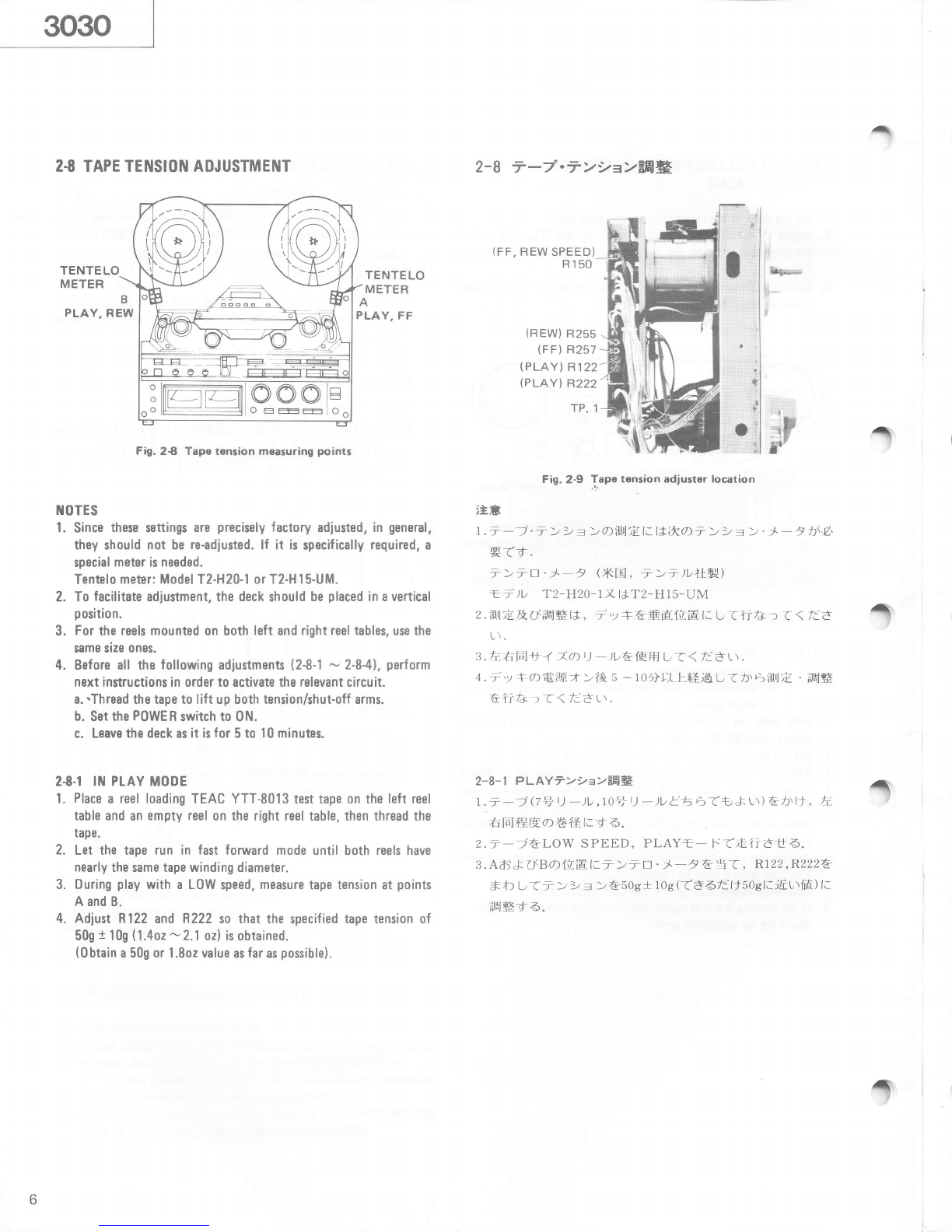
2.9 TENSION ARM HEIGHT ADJUSTMENT
1. Thread any standard tape oh the deck using a standard empty
reels such as TEAC RE-1002.
2. Set the deck in the play mode.
3. Stop left (right) inertia roller's rotation by hand.
Adjust by turning the left (right) tension arm height adjusting
screw (refer to Fig. 2-10) so that the tape moves in the center of
the inertia roller.
II0TE: When adjusting, pay special attention to the relationship
between position-detecting shutter and the opening of
photo-interrupter to prevent, for example, the shutter
from being caught.
4. Release the inertia roller. Fine_adjust the adjusting nut again
until there is no tape curling on the tape guide pin between the
erase head and the left (right) inertia roller.
5. After Adjusting the height of both left and right tension arms,
check that the tape running condition is good by switching be_
tween fast forward and rewind modes.
6. lf the tape running position is different when the inertia roiler
stops and when it turns, the conditon when the inertia roller is
rotating has priority.
2-8-3 FF7>2e>=:dl*
1.'ti-4|F.\at.) -)tJ(Eu _)D) atrt U<FF=_ t-.trr5
( i - i t +_1- d t rs Lr#i f-E t. f+ I ) .
2. AaltE I.- >- D . J_ _ t & \7,R257 & *b t T _ > >
= > t ltog + 10g ( t g a t: ttl 10s t.iE. r\1d) lr 6gq 5 .
aa : FF(REW)Wo)tj-_t ftrlj-j. ->> = > (/\,y j
. - > > = >) I*,2_72-zrFt.i6^6 FF REW) r_7.
7.u l-.;iEgt..k u HsrF!t.Ev t_dfi*d.
2-8-4 REWT>!=>EB*
1.ti-4lFtlat.) -)D(x71.) _)t )6Hf t, rREW=_ F t.d
4 (= t & rt.fi tt td.r\)DiLq t.{*l) .
2. Bo)[XEI.- >, D. )_ _ t & liT,R2556 *b l:T i > ) =
> t tt}g + r0g ( t6 6 fc 111 tOg tti[ urifi ) tr 694 5 .
i+. : FFSREWd)t> j/= >l3:t6.6r\- U+ U < T6.
2-9 7>>=>7-L.A+EH#
f .i.y.FO=- F :pLAy.
2.ffi# l, e. - xt 3l1tl.: h 4 ts E - - alpld,^& +< tr..r, fi
-r h.tr -oE>t_tj )h\rt.ftt6&)t.j>)=
> p - 1lF,d AEISJ-,y F (Blz-r\+Hil &ffi#-{ 6.
3. +f{Frtd11 t:h -( ts E - - tfh. L,,i-l t-. tr _- tiH*
^'y f a ffra- - i fi 4 I- L > aFfr< = _ ) h\h _ )t, U f+
L\A ) l.BE- ) )t = )t 7 - Ata'dffig + jl,& lffiffilgt 6.
4.thD-)) = ):p -A€:dffi#1*., FF, REWr)ffiE tJ$,
lF6: 1i'> T - - ) rt.Tr ltffi& n 6 .
i*. : h'( t- D * - &E tldiltE+- E*ndlitrF*t < t _ j
rt.1iln-Eh\qILt 6t+.*ttti-r F. ! --tEl$x +a j_J
+J re@%t 6 .
Figure shows left side tansion arm.
I'xl l* lr.lF.tli > > = >. p - A&it .
\
ctension arm
height adj. screw
positiondetecting shutter
Fis.2-1o
left tension arm

{
2.I|l REEL TAELE HEIGHT ADJUSTMENT
1. Adjust the tension arm height beforehand (See 2-91.
2. Check each reel table height using a TEAC RE-l 002 empty reel
and letting the tape run in each tape operating mode.
3. lf the tape rubs against the reel flanges, adjust the reel table
height by means of the two reel table mounting screws.
Fis.2-11
2.II TAPE PATH ALIGNMENTS
The following procedure is for parallelism adjustment of left pinch
roller. A similat procedure is also applied for the right pinch roller.
2.1I.I COABSE ADJUSTMEI{T OF PIttICH ROtLEf
PARAttEtISM
l. Let pinch roller draw near toward capstan shaft by manually lift-
ing up tape lifter shown in Fig.2-12.
2. Check pinch roller/capstan shaft parallelism viewed from direc-
tion of arrow A shown in Fig. 2-l 2. ( Ref er to Fig. 2-13, 14.)
3. lf not parallel, loosen the reinforcement plate screw near the
corrocti0n-required side (Refer to Fig. 2-15), then correct tilt of
pinch roller spindle using correction iig. (Part No. 573600100).
Adlustment can be done by tilting correction jig in direction of
arrow A or A'.
IIOTE:
(l) Use the iig as near as posible to the pinch roller spindle.
(2) Do not touch the surface of spindle.
(3) Use no other tool for this adjustment!.
4. Remove pinch roller, then push up tape lifter to visually align
pinch roller spindle with the capstan shaft viewed from direction
of arrow B in Fig. 2-12.
5. lf nbeded, adiust by tilting correction jig in direction of arrow B
or B' in Fig. 2-15.
2.11.2 FITTE ADJUSTUETIT OF PITICH BOLTER
PABAttEL ALIGIIME]IT
1. Repeat play and stop and confirm tape travel positioning does
n0t vary.
2. lf necessary, adjust pinch roller alignment as shown in Fig. 2-15.
2-10 t)-/t,6H*eB:g
\.-w1tRcl 7 ) ) = )' 7 - /lHtffif'1Al-+ffi*& 1 i ) < < T:
d L\.
2.TEAC RE-1002 t) -)vtl€,ffil', &7-)6h1ts<--ih\
| ) )u. ) -> tl.+*ffit 6h,x- h,&* t'v 2t 4.
3.€ t {*f;4t6t*+t*t) -)ve&taa u(t\6 2 +o+>&
vi 6b. u - )t awftlaa&atlh' t'<ffi#-{ 4.
2-11 7_J€FEE#
t>+- D-- t-+p ) t >' > t, t t- t-a+1it€.l*, --
i 811 a EE l. ft b € 4 rd=F{tr<t .
D) f I.E t- > +. D - - at'1-r trffi1go1tV6:S^*dr\, {i
t>+. D 7l.lLrT5[n']tfr1.ffi# l,( | dt\.
2- | 1 - | e>r. tr--+ tr EalF.##
r.-&+1')t t>.>) t' l-iEilJ.6.
2.82-r2L4it A E6.th'"]- nT, E>+' D.-- X+1- 2 ^t
>'> P) lc.]+11EtJ rv 2-{ 4.
3. Y 11 T f+v:t$A l*, ffi *tF A lfffi U T E<12- 15 l. )t.d' A X
l*A' tftr t(. L > +' n - =tfro:l€'d 6:lttLi 6. (##t+ l*
,1l1r< 6 -: It E > +' tr - -+ts l-i[ t\{rIE l- 1u'v l- U ( I' d
L\) . (ffigt+ 5A#57360001oo)
4.ikt.t>+.D--&t+t, --t. t)t t& l,tJ, x2-12
a Bfifi1nt6 aT L>+. E -- t +p t 7.t >' > p ) f
a*118&+r'v it6.
*11Tt*.v:t*,a^l*, ffigtFtftH t Ttrlz-ls l.-q R X l*
B', fr 6t t. t_ > +. o - -*fi /){r€- t It* *,t 6 .
2- | | -2 C > +. E - - +,t':, tr'ffiffig
r. pLAy sTopaf*iq u --i+-ft1nEh\q4Lur{u\ - t_&
6E7Et6.
2 . E U *. +L-{ 4 tE e ,dxl2 - 1 5 0) h i*< t- > + . D - - *fr o lq.3
&'{&ffiM-{ 6 .
T

('
capstan shaft
Fig. 2-13 View in direction A (example of non-paralletisml
FiS.2-12 Directions for pinch roller parallelism check
pinch roller
spindle
pinch roller shaft
FiS.2-14 View in direction B (example of non_parallelism)
correction jiS (TEAC P/N 5736000tOO)
I | ^ reinforcement plate screws
o, I lft (Loosen the correction-required side)
f
)
FiS, 2-15 Pinch roller/capstan alignment

$
2-12 TAPE SPEED ADJUSTMENT
OSCI LLATOR FREOUENCY COUNTER
cH2
LINE IN cH2
OUTPUT
Fis. 2-16
2-12.I PtAY SPEED
1. Connect a frequency counter to either 0UTPUT terminal.
2. Load TEAC YTT-2004 test taoe. Set the SPEED switch-HlGH.
and PITCH C0NT knob-0FF.
3. Play the tape. Adjust HIGH SPEED control (see Fig.2-17llora
reading of 3,000H2 t5Hz.
4. Check the following at the beginning and the end of the tape.
Specifications:
Tape speed deviation 3,000H2 130H2
Tapespeeddrift.. ......15H2
5. Change the test tape to a TEAC YTT-2003 and SPEED switch
setting to L0W.
6. Bepeat steps 3 through 4. Adjust LOW SPEED control if neces-
sary.
Pull the PITCH C0NT knob out. Set SPEED switch H lGH. Play
a YTT-2004.
Check if the speed variation of at least 3,000H2 +180H2 is ob-
tained when the PITCH C0NT knob is rotated fully in both
directions.
Change the test tape to YTT-2003 SPEED switch setting to
L0W. Repeat step 8.
FAST WINDING SPEED
l. Set the deck in vertical oositi6n.
2. Connect oscilloscope between TPI test point on the P0WER
PCB and ground.
3. Thread a TEAC YTT-8013 test tape. In this case, either use of
Tinch reels or l0inch are permitted provided both leftand right
reels are tha same size.
Ouring fast fonrvard or rewind mode, adjust R150(see Fig. 2-9)
so that wavelength displayed on the oscilloscope becomes 7msec.
(Fig. 2-18). Adjustment should be satisfied at any tape winding
position.
Check that almost equal value of fast winding speed is obtained
between fast forward and rewind modes.
2-12 7-/.zH-t"EEg
2-12-I FWD/REV PLAYZE'-F
\.ffi#lqFfr X2-17+nq
2.--).7.tr- l-.iiEgF+ ,E'y J. r l/ F tr -)1,, .).4 'y jl*
oFFt-t rdi<.t.
3.ffi.t&
-
-;
2-12-2 FF/REW.XTJ-l.r
7.)\.) *+Fa.]_TP. 1(Bl2-s8F1.) t-t>D7-_t )e#frft:+
4.
z . i 'y *?I*FF.E - l-- X I*REW= F. l. t .6 .
3.TP.loiEfrtaiQF<h\7 m sec {if*5S - l. R150 (X2-s+n4.\
effi*'q 6----..[x2-r8
4. FFt REW(z\A faf;/lfaY:. X&6EAEd 6 .
Fig.2-17 FWD/REV play speed adjustment points
Fig. 2-18 Waveform at TPl
f
7.
8.
9.
4.
5.
!
DECK
under TEST
capstan motor
HIGH SPEED
LOW SPEED
10

2.13 WOW AND FLUTTER CHECKS
N0TES: The following measurements should be made at the
beginning and the end of the tape.
Playback
1. Connect the test equipment to the deck as shown in Fig. 2-,|6.
2. Load and play a TEAC YTT-2004 test tape for HIGH speed
(38cm/s or l5ips), or a TEAC YTT-2003 test tape for LOW
speed (19cm/s or 7-Yrl.
3. Read the indication on the wow and flutter meter.
Specifications:
2-13 ,r.72y?.7-.y2
I*,lHi-j YTT 2003 """"LOW(l9cm/sec)
YTT 200,1.........HIGH (38cm/sec)
7 \'r | ) )lrI€.ll11+o E|lf;Vt /kr-t'El* |.) &iHI i.
+J- tl,. iJ: s* ++ iJ:
T ) l{t2 RMS WRMS RMS
1 9cm/s 0.10?l o.o5o.4 0 . r2?z
38cm/s o.o8?z 0.04?l o . r)az
2-14 iiifi
i'v * d) lpl *r;1[ r] (. t* 1 000H+ Ffl ft ffi fu "t r". tJ I 4. t. I tpl f?E
ii,ifrrr,z'*rd.
n 1 )ttt, TEAC^U> | )r.t I )t(TF,AC TZ.255t 1 )U.
.F'y F) XlJMobil D.T.E.n { )r--1 t-+6'l*.H1t,r<tar\.
f .i'v*t*'f-ir:Et-H<.
2.7>>=>.D -,ti1 l-..tr -,tr) f.tr -t.t**tiffi,
+ p - 7 t > tr ts'iff , ? n< nvlz- I 9 tr it-Ffi ?a;a,fElFf
t.ii,ifi f 5.
3. iiifi l* ?r& 5 f+ rr& ), */:7 1 E1 i #Bt, t- t 4 )th\ l.f
?? L r*Lrt -r ii.na L r < f:A r\.
Figure shows left side. 0o also for right side.
tension roller inertia roller
,r'----\
n|l
\2 \+-,,
J_ 6-
g tra5'h
YV
A.z E"
- -q z4Y:t
/(4).\
Fis.2-19
HIGH (38cm/s): 0.04% WBMS
LOW (l9cm/s): 0.05% WRMS 0.08% RMS
0.10% BMS
r
IF
0verall
4. Load a TEAC YTT-8013 test tape (blank). Apply
3,000H z signal.
5. During simultaneous tape monitoring (playing)
signal, read the wow and flutter meter display.
Specifications:
and record a
the recorded
HIGH: 0.10% RMS LOW: 0.12% RMS
2-14 tUBRTCATt0N
0iling is needed after every 1.000 hours of operation or once a year
if the deck is infrequently used. For this purpose, TEAC spindle oil
(from TEAC TZ-255 oil kit). Mobil D.T.E. 0il Light, etc. are recom-
mended. Lubrication is normally not necessary except at the points
shown .
l. Place the deck in the horizontal position.
2. Apply a few drops of oil to therespectivespindlesshown,exclud-
ing capstans, then spread the oil evenly on the spindle surfaces
using a cotton cloth, etc.
3. For capstans, apply a few drops to the indicated position.
4. After oiling all the points, leave the deck for 1 to 2 hours until
the oil is thoroughly absorbed.
2-15 VOLTAGE CONVEBSION
(FOR GENERAL EXPORT MODELS)
Voltage Gonversion
1. First remove the two feet by removing the screws in each one.
2. Unscrew the left and right sides of the cabinet.
3. Locate the voltage selector as seen from the top side of the deck.
4. Turn the slotted center post 0f the selector with a screwdriver to
match the numerals corresponding to the voltage requirement of
your area to the point marked "SET UP V0LTAGE" (click
sound is heard).
5. Replace the cabinet and feet.
capstan
tu
r
pinch roller
r.-\
\-!=r'
g
a/€t$\
|.'=-]
v
H
\ cl/
I
f
Fig.2-2O
11

^
2.16 HEAD ALIGNMENT
There is no need for head height and tilt adiustments because the
record and playback heads of 3030 are a semi-fixed type (erase
head fully-fixed).
2-I6.I HEAD MOUt{TIttIG (BECOBD AND PLAYBACK HEADS)
1. Refer ro Fig.2-23.
2. With head mounting screws, mount heads to head mounting
plate. Attach shield case to the playback head.
3. Mount head as'y to head base using mounting screw and mount
tangency adjustment screw.
4. Mount azimuth adjustment screws.
2.I6.2 PTAYBACK HEAO AOJUSTMETTT
1. See Fig. 2-24 tor necessary connections.
2. Set the 0UTPUT switch to REPR0.
3. Run the test t3pe TEAC YTT-I003 in play mode to reproduce
the 400H2 signal on the tape.
4. Slightly loosen the mounting screws which hold playback head
in place and adjust the tangency using adiustment screws, for
maximum output. When the maximum output is attained,
retighten both mounting screws.
5. Play the l6kHz signal on the tape and adiust the azimuth of
the playback head using adjustment screws for les than 45"
of phase difference between the two channels (see Fig. 2-251.
I{OTE: Azimuth adjustment should be completed by turning
adjustment screws in tightening direction (clockwise).
6. Set the PLAYBACK HEAD wrritch to 4T and perform thesame
tangency and azimuth adjustment procedures to 4 Track play'
back head.
2-I6-3 RECORO HEAD ADJUSTMEIIT
Proceed to record head adjustment only after playback head
adjustment has been completed.
1. See Fig. 2-24 for necessary connections.
2. Set the 0UTPUT switch to REPB0.
3. Load the blank test tape AMPEX 456 and record a 400H2
-10dBV (316mV) signal in recording mode to reproduce it
simu ltaneously.
4. Adjust the tangency of the recording head as in step 4 under
paragraph 2-1 6-2.
5. Simultaneously record and reproduce a l kHz. -20dBV (100mV)
signal and adjust the azimuth of the recording head using adiust-
ment screws for less than 0o of phase difference between the
two channels (see Fig. 2-25).
tt0TES: oAzimuth adjustment should be completed by turning
' adiustment screws in tightening direction (clockwise).
rBe carefull not to confuse the bias signal (150kHz)
in measurement.
2-16 r'7 l."FEiE
i:t030o$*#,\)i l- LE4E,r y l- l*'+.16l€il(i'Hli,\'y l-. l*i,1:
El €-\ ) l. /.r r ( \,\ t 3 . - a T. &) \'t t- O E d JhItE t: t ), F
-,;r4*ttTt<-{.
2-l 6-l IzFIF'f{ (i*E^ vlj, t*.^'zF)
t.Fig.z-234F.H
2. r. v l- 4Uf ? )i,r'v t-- €z\ v F qrf'f+E l. tr €d 6 (^'v
t-Ass'y) . -D t dF4,r'v F. la l*i/-r, f ' lt-)-&E'v
F-f5.
3.rr.'y FAss'yA^\'y t-. 16l€+ jit,\'y t-.EfErJ*:u -C^'v F'
rr-z.ll4f {,lli6.
4.7 tn )-ffi#+t&n\fti6.
2-16-2 E*;.y1.'38#
I . t**fi Fis.2-24
2.OUTPUT^4'Y7 : REPRO
3.TEAC YTT-1003- ). - 7. h. aPLAY€-l-.t€iiat,
aooHzZ5ltE+.t6.
+.F4zr.v l-r)^.y FIfl€+yat1r*EdD, ,r'v l- ElFrJT
) & E t- l.€hh\ u ( 4 00 H z$'{ts iE i n\ft /< l- f*5 & f ^'v l-
a 6+R | ) Atr &ffi# { 4. t1t€+'la &tfii + ) tt# b 6.
5 . it r- YTT- 1003o) I 6kH zF tl &Hry U,CHILCIr2o ff iH+.
7)\4s" J--ltt l:fs.45- 7 t.? ^ffi'g+ttffi#t 6.
(Fis.2-2s)
tt . v ).2 z.ffi#.+) tttFb 6fr 6t (A tol l-) <ffi#tft*
6J_t_.
6.iAI'PLAYBACK HEADA4TI' L, F;CtEtFd)+ltIFi,
4TB+.,\'y f-t)^'y t--H+& rJ t 7 )? 7otffi*&11r+).
2-16-3 i*€r'vl'iE#
$*#,r'v F. ffi gd)Hil t.EaF^\'y l-' ;Egrif{ -) ( rr 5 i t .
1.itfifi Fis.2-24
z.OUTPUT;4'yf : REPRO
3.AMPEX 4567 zxP'y I to, 400H2/ 10dBV(316mV)
I=; \ | & 11. u L /.rz5i D ld FtEi+t 6.
4. E. aE ^'y t- -;.Fj 43 t E i* r. S* F ^ .y l-- d) H l,F | ) fu E & ill+
-r 6.
.r . ikt. tkHz / 20dBV ( 1 00mV ) t,; 4 e *.H's:++. a cllt L CH2
altt.+tr*h\ 0" tllFl l-fa53 -7 t.? ^ffi#t6.
(Fie.2-25) .
t*. . 7t.? tffi#?-tttffiet6fr6t (fifElL) <ffi+t
*&6- t .
. )\4 7 t t€+ (lsokHz) AiRl -€ L f+ tr & i itHi
6.x.
$
f
f
tz

29..o
\9.j d6)
\@
io:
ig,i 10i
"\@j
\-'|
\
t*-
Playback Playbac k
Fig. 2-21 Head arrangement
Adjustment screws
head base mounting screw
Tangency
Azimuth
Fixed (not adiustable)
tangency adiustment screw
azimuth adiustment screw
head base
head mounting screw
O
o
@
q
(-
azimuth adiustment screw
head mounting screw
head mounting
AZf MUTH 7'/ ? 7
The gap of lhe head core should be perpendicular to the
tape travel.
^./ l. : 7o+ ?./ Jh:- _7 fri-tf"-l{_liL (*
E<'bb - t .
Fig.2-22 Head regulation elements
LINE IN OUTPUT
Fig.2-24 Connection for phase check
shield case
(playback only)
FiS. 2-23 Head niounting
oO (tN PHASE} go"
(A
\r/
TANGEI{CY I 1'RI)
The dolled line should be perpendicular to the surface of
the tape.
r'v l.of,L.fiR (F,tR) ht--J{:*E<'64: a.
DECK
undor TEST n
oo
F iS. 2-25 Conf irming phase relationship
13

3 ELECTRICAL ADJUSTMENTS AND CHECKS
7>/*ggr-ffi#tfE-#. $
3-r ADJUSTMENT POINTS LOCATION AND CONNECTION
'EEIEFEI'*fT
f
f
f
Fig. 3-1 REC AND PLAYPCB adjustm€nt and test points
f
R550 / R950 2I P layback IQ R563 / R963 Low soeed Rec t0
R551 / R951 4T R56i / R96i Hish speed Rec [Q
R554 / R954 2t Playback level R51? / R972 Rec bias
R555 / R955 4T R576 / R976 Phase shi ft
R556 / R956 0utput level t301 / 1401 Bias trap (playback)
R557 / R957 Input level L 304 Honaural Rec t0
|i55B / R958 VU meter 1306 / t406 Bias trap (record)
Rs59 / R959 Rec I eve I
14

t;
I
Fig.3-2 Headphone PCB adjustment points
NOI tS :
1. Before perf0rtning adlustments and checks, clean and
delnagnet ize the enti fe tape path.
2. In general, adjustntents and checks are done in the
0fder 0f Ci]-1 then CH-2. Double RIF. Nos, indicate
Cll-l/C|.l-2. (txample : R550/R950)
3.0dBV=1.0V
4. The AC v0l tI|leter used in the procedures |tlust have an
i nput impedance of 1H-ohms 0r lll0re.
LINE IN
Fig. 3-4 Connection for PHONES level check
it,a
1.7 >7ffioffi& . MZLoffiIx, i-7ft.',fr*/)iHBL iHtfi
t'fi',( ( /jE lt.
2.++titFft.a*!\[E D, AfilBlJ CH-1, cT-z a]EftT'frfc ")
( ( /i3 t,t.
r{ Rs50/R950 /)} i {t;d,3fL(lr5gg*utJ cH-1/
cl|-2 tzrL*,f.
3.0 dBv = 1.0 v
4.WlEirlHHf bv<)va+a^fi4 Yv-yvxtJ 1 HQ ttl
La{rattf.ffi L( ( t3 t,r.
oscr LLoscoPE
DECK under TEST
AC Voltmeter
TEST LOAD RESISTORS
15

$
3-2 PLAYBACK PIRFORMANCI
g.++ Test mode
FIIV- lnitial deck settings
0UTPUT cont. : Scale position "7"
OUTPUI sl : REPRO
REF LEVTL sw : 250ntl
Test tapes
YTI- 1 004
YiT-1003 :
15 ips )
t-1/2 ips )
For 38 cm/s (
for 19 cm/s (
And be sure lhat vhole frequency satisfy specificati0n with both speeds,
38 c[l/s TF,ffiaw++ir xr,/rl uf,etj 1 I cm/s (.FiFEt6r, ), Ex U* l:*fi$gtlr'.r-16 .
$
$
f
3-3 MONITOR PiRTORMANCi
I
Deck settings
LIili cont. :
OUTPUT c0nt,
l'll0 cont. sw I
0UTPUT sit
Scale position "7"
Sca le posi t ion "7"
HIN ( unless other.lise specif ied ++t.+AftCIbb8Ath< )
INPUT
I iiH
;ffi]FE SIITING I INPUT SIGilAL
-# E ', xhEE ADJUST
ffiHFf RESULI
#EG REilARKS
ffit
1. Playback head azimuth
E/*r'y F .7i?7 11
l-l Connection . FiS.2-24
t*ffi YTI- 1 003
( 16kflz/-10d8) Azi[luth screl{s
7r?^3w yPhase
{ilffi within 45"
4s''IIFJ Refef to
F is.2-21
- 2-?5
2. Play back level
Nkv\tv l-l AC voltlnetef to litC
and PLAY PCB TP,O,I/
iP.11 and oND
YTT- 1 003
( 400|-|r/0dB )2I
4l R554/R954
R555/R9ss TP.01/TP.11
-6.8dBV (450mV)
OUTPUT :
-12.6d8V
(230|[v)
3. Frequency fesponse
Htdffi++tt
J- |
Spec. PB condition
ffiErF4ttE
SPEED sv : L0l,l
Ytr-1003 | zi , nssoznsso I
(4ooru/lokltz) | at : nsstuRsst I
0UIPUT : Nearly equal output level (+1.5d8) at both frequencies.
Then check frequency response. (Fis.3-6)
ffiH6ofr)1n{itrgL < ( + 1. 5dB)rr6 } j iffi .
tofibffiWffi**tt'v2 (tr 3-6 *ffi)
3-2 SPiIO sw || IG|'| YTT- 1 004 Check
4- ^. ,., tOUTPUI :
Frequency response : Fig.3-5
Hiffiffitt : EI 3-5
If the high frequency level doesn't satisfy specificati0n with 15 ips. readjust it with 7.5 ips.
I TEH
iffiIFH SITT I NO
ax rb INPUT SIGNAL
^fitr8 ADJUST
4ffi6-Ff RESULT
dffiG RTHARKS
ffi*
4. Spec i f ied LINt
INPUT LEVEL
LINI flEl'rl,^Vt
AC voltmeterto REC
And PLAY PCB TP. 03/
TP.13 and Gt{D LIi{E II{ :
lkHz / -10d8
(316|[V)
R557/R957 IP.03/TP.13
-4.2dBV (61snv)
A-t Connec t i on : F i S. 3-3 R556/R956 0UIPUT : -1OdBV(316nV
5, VU ll|etsr
t-tffi t-1 LINt spec. i nput
condition
rrr{E ffit/'rfitr Same as above
ItrJ IR55B/R958 VUllleter:0VU Refer to
Fig.3-2
i,
I
PHOIIIS II{PUT TEVTL
\.7 l.frYHitJL"VI, o-t Same as above
IqJ -r,
Same as above
lHl l_ Check
ts.'v ?PH0NES jack :
-1',ldBV +2dB
(224mV-354mV )
8 Q load
8QF?ff
Fis.3-4
l7 l,lin. HIC input level
HIC frzhl.,l:l,"Vt, 1a
t-l HIC cont, : HAX HIC II{:
lk{t/-7zdBV
(251 rrV)
Check
*t'y 2OUTPIJT :
-1odBV +3dB
(224mV-447nV)
16

e2-l RTCORD I NG PIRFORMANCI
$?€fi Test mode
R-EeTpllv- Deck sett i ngs
REc--IUileTI0[lw :
DBX sw :
RtF t.tVtL sw r
OUIPUI Sw ;
OUTPUI cont. :
LII{F cont, :
HIC cont.
BIAS FINI cont, :
C|-| 1, 2 both 0N
OUT
250nl,l
REPRO
Spec, PB condition
Spec. input condition
Il IN
Centef
Test taoe
nttPEXJS6-: Blank tape
I ITH
iHg'qE SITT II{G
tl ,tl II{PUI SIOI{At
^htrn ADJUST
ffitr'Ff RTSUTI
iffilH REMRKS
ffit
B. Bias tlap
)\477 F1y7
B-1 AC volt meter between
TP.05/TP.'15 and GliD No signal
#lzE 1306/t406 TP.05/TP. l5
Hin. reading
,'{,f 7xifil'ujFzjr B ias
f requency
)\477
Eiffi
150 kHz
B-2 AC volt meter between
TP. 01/TP. 1 1 and GND
No signal
ff=g
*tE ? 1301/140'l 1P.01/TP. 11
Hin. reading
,'{4 7:,if;*rjFzJi
Record b i as
g*E)\4 7 ^9-1
First set adjuster ful ly CCl,l ( O ), then adjust,
&l/Ji3+EE[tntE -{tr{,rF] L(r' 63ffi tf6D6 .
SPttD sw : L0l,l LIt{I It{ :
1 0kHz/-20dBV
( 1 00mV) R572/R972
OUTPUT :
Over-bias value
t-i l- .)\477rG:
7dB +0.5d8
10. Record lcvel
$*€L'&1.
'10- 1SPEE0 stl : HIGIi IINI IN:
1 kHzl- 1 0dBV
(316mV)
R559/R959 0UTPUT: -10dBV (316uV)
1 0-2 Check tt't 2VU metef : 0 VU + 0.5 VU
1 0-3 Same as above F"lI
DBX sw : IN Check
4-. .', t0UTPUT : -10 dBV +1.5d8
(266ltt/ -376tnv)
Same as above tiilt
rn-,,! OBX sw:OUT
0UTPUI sw :
I Rt PR0/ INPU)
No signal
F,f=kj Check
tt'v? OUTPUT :
Bias leak :
t\477Wt:
less than -50dBV (3.16mV)
After adiusting overal I frequency response (ite|r| 12 and 13), re-do this item's checks and adjustment.
^ffiB . ;Jffill$*l4tdr4ffiffi+tiJ:I#(12 13 E) ?{, HF.rla.L.
1 1, Record head az i |Iluth
S*H'.: v l: .7r?]. 11-1 SPttD sry
OBX sw
L0t4
0tJl
LINI IN :
1 kHzl-20dBV
(100|llv)
Record head
azimuth scfeys
$*F'r'v F
7y?7w iPhase : 0'
{ilffi : 0"
Refer to
F is.2-21
- 2-25
lf you adjust azimuth smerys, check pafagraph 10-1-3 again.
7' ? ^iw|^ J tfih't-/:BhH, 1 0-',1 -3 trtE* r .y 2 t b J. t
12. Frequency fesponse
J*ltwi+t+
(SPtt0: lllGH)
I L' ISPIE0 sw : lllGtl
DBX sw : OUT
IIt{I It{ :
400H2 & 2zkltz
/-20dBV( 1 00mV) R567/R967
OUTPIJT :
tqual level at both frequency
Wlili}s.othnsL(*16 j j
iffi
I
tt-L l
i
tINI IN :
-10dBV(316[|V) Check
tz'v? Frequency response : Fig.3-7
Eliffiffitf : E 3-7
12-3 Same as above Et
DBX sw : Il{ Same as above
lql_t Check
*r.'v ?Sane as above
Itrlr
17

I TEt{
;ffiFE StTT IIIG
dx. ,lt: IliPUT SIGIiAL
X)itrA ADJUST
iffiH-Ft RISULT
tffitE REMRKS
ffi+
13. Frequency response
ffli4&f+tt
(SPEtD: L0l4)
1 3-1 SPIID ST
OBX s'r :
: L0ll
OUI
LIilt IN :
400H2 & 20kHz
/-30dBV(31. 6[lV)
R563/R963 OUTPUT :
[qual level at both frequercy
ffiHffiCIfrfii$L(116 j j
ffi
IJ-Z LINI II{:
-20d8 (100|llv) Check
1- - ,,,4 Frequency response : Fig.3-B
Eiffiffitt : El 3-8
I J-J Same as above l-til-.]L
DBX sw : li{ Same as above
Itrtr Check
*t'v7 Sane as above
ItrJl
14. Honaura I record i ng
t,,t1)W*E
't4-1 SPIID stv : L0l,l
DBX stt : OUT
RIC Ftit'{(). sw :
0lll :Oti, Cll2:0fI LIt{t Iil:
-30dBv(3'l.ornv)
t 304
I requency response : F i g. 3-B
HtffiC+tt : El 3-B
1i-t Same as above Et
RIC FUI{C. sw :
()tl1:0FF, Cll2:0N
Chect(
+-..,4
15 BIAS FINI
)\472.2r4/ 15-1 SPItD sw: L0l,]
DBX sw : OUI
LINt I|{ :
1 kllz/-10dBV
(316mV)
Assurl|e 0n outout refefence level obtained \vhen the
BIAS FINI button is set t0 center. Turn BIAS FINI
coll|pletely t0 left and right and check that output
level varies between -2.5 dB and +1.5 dB or hisher
against the refefence lever.
B I AS FINI tJ. alht+y, tiltr.0>6o1g7tt##L^Jt.
Lf6. BiAS FINE -t*.h*ffi*fil3,qLf:Wo>frfi
,arp73t8Flz^JHtf'l L -2. 5dB, +1. SdB t)llgYLf
6ZL.*1-t'v2t6.
After checking, be sure t0 set BIAS FINE EAC|( t0 the center Dosition
* e'y ?l*, BrAS FINE 2r.4t+.> t{ilECtFL(*i< : L .
16. Di stort ion
E+ 16- 1Same as above IAI
SPI iD sw : tilG|l
LINE IN :
1 kHzl-10dBV
(316mV)
Check
tt'v ?
DBX sw : both Iil & OuT
Total hurnonic distortion
+HiEifttEless than 0.8 x
17. Signal to noise ratio
s/ti !L 17 -1 SPtID sw : l]lGtl & t0ll No signal
*f=€ Check
tz'y? iach sPeed ffiJE :
better than 52 dB
18. Erase efficiency
iH*4FR 18- 1
Record a 1 kltz signal, rewind and erase portion of the recording. Playback the tape t0 conpare
the output level from the original 'l kHz recording yith the level from the erased pofti0n.
1 kilz €Bt$**f**FL(--StiFi*, *iH*#j}LiH*#$h0> 1 kHz firr,^('Ltaflft.
Connection is same as in Fig.3-3, but engage l kHz filter. 'l kflz B.P.F. lFffi.
Thc ryorst value should be within spec. &Effin*t&tlEEf6:L.
Specifications should be |net even yhen BIAS FINI is turned down to its minimum setting.
BIAS Fllit .;:t ts&y'r?L1tffi trEEf zo : L .
SPIEO sy : |-il0tl LINT IN:
1 kllzlodBV
(1V)
Check
7t'v 7Better than 68 dB
19. Channel separat ion
Ar4'tV'
t)\V-:z z Yt9- 1
.Connecti0n: Fig.3-3, but do not cOnnect LINE lN (CHz), and engaoe 1 kHz filter.
1 kHz B, P. F. ffrffi
.Set the deck to record mode. Find the difference between the 1 kHz recOrded p0fti0n (Ctl1) and
check reverse portion.
1 kHz $*#*il,} (Ctil) L*f=+$**#r| (CHz) o 1ktlz F4,fr)1v<tw)#tu[8. cH1, CHz t
MtE it:&# i:?! \( LA t'y ? .
SPttD sw : HIGII
LII.IE ItI :
Ctl 1 : lkHz/
-1OdBV(316nV)
CH2:Nosiona
Check
ttv2 Better than 50 dB
s
f
f
f
t*
18

,f_
a3-5 FREOUENCY BESPONSE
Itl)&fit+,lt
3-5-1
(dB)
+4
+3
o
-3
PLAYBACK
22k I Hz7
Fig. 3-S Playback frequency response (38 cm/s)
40 tk Z?kt1z!
Fig.3-7 Overall frequency response (38 cm/s)
----------1
-6 t------- J\----- ---_J
IK 2Ok IHz]
Fig. 3-8 Overall frequency response (19 cm/sl
IN
0ur
3-5-2
(dB)
+6
+3
o
-3
-6
OVERALL
t------ --\
( dB)
+6
(dB)
+3
0
-3 +3
o
-3
- --- dBx
-
dBX
---- dBX rN
-
dBX oul
400 20k tHzl
Fig. 3-6 Playback frequency response (19 cmls)
I IEH
;FgFE SITI I t{G
eftE Il{PUT SIGNAT
xrtrE ADJUST
iffifif-ff llISULI
iffiG RIHARKS
ffi*
20. RTC HUTI
RtC HUTI funct i on
YrX 20-1
. Connection : Fig.3-3, but ensaoe 1 kHz f ilter. 1 kHz B. p. F. l"fH.
.Record a 1 kHz signal. Push REC HUTI button for several seconds. ( At this time, make sure
LtO 0n the button lights ) Reyind and play the tape. Find the difference betleen tfp 1 kHz
porti0n and "rec-mute" pOfti0n.
1 kHz {E€t$**L, B+? Rtc HUTI fitffiL(*Ff=€#r}ttFb. .o)i-ztH&Ls*Fg6j}l
*lEE#h t o)flh v,eratfiIef 6 .
SPTED sw : HIGH LINi II{:
'l kHzl10dBV
(316ltV)
Check
4- - ,,,4 Bettef than 65 dB
21. Phase sh i ft
,/ I*./\ . >/ /L t' ISPtiD sw :
H IC,tl L0ti
LINI IN :
4Kllz sawtooth
trfrffi.
/-30dBV(31.6|l|V)
R576/R976
Cofrect waveform
J&
Incorrect yaveform
4E
19

$
3€ DBX PCB ADJUSTMENT
TIOTES:
l. This section adjustment is not usually needed unless an ad-
justor(sl have been changed 0r a component(sl on the pC board
have sustained damage, since the PC board has been precisely
adjusted in the factory.
2. Turn the deck 0FF to prevent accidental damage when removing
or replaceing PC board.
3-6-t ADJUSTMETIT p0tilTS L0CAT|0trl
N*fiEF
3-6 DBX*+E+,f+EE#
rit
1 . D B X + fh o &Y, F" \ t*E li f+'> t; r* 6 a |tt, i6'H I A DB X*tE
HfTd);iE45l*4iX<i .
z.*tEr,I +t t&rttt*?;t&,L't j'y +aEttR&tJJ )Th\
411t*'; (< /:at\.
lcilRch
EilCODER
\L/)-t )
n27/W28 YGA symmelry VCA'>>./lt)-
R723/R724 l{ominal level ,S+v ^ )v
R753/R754 RilS symmetry RMS 7 >r/ l- rJ -
IIECODER R627lR628 YCA symmetry vca->>t t-t)-
R623/R624 llominal level z*Ev ^)v
R653/R651 RMS symmetry RMS'>>.'1 lt)-
Fig.3-9
3-6-2 VCA SYMMETBY AOJUSTMEITIT WAVE FORM
VCA i>ttt)8#.iEY..
Fig. 3-1O RMS symmatry adjustment (incorrect)
(RMSr>./l'rffilE.TF) Fig. 3'11 RMS symmetry adjustment (correct)
(RMS>>./l.U-aEE.H)
A
J\ .A At\I
\\ \
\\
LI \/ 1IVI \\\/ V\/ lV
20
Table of contents
Other Tascam Tape Deck manuals

Tascam
Tascam BR-20 Series Guide

Tascam
Tascam 34 Troubleshooting guide

Tascam
Tascam BR-20 Series Troubleshooting guide

Tascam
Tascam 38 Installation guide

Tascam
Tascam 34B Troubleshooting guide

Tascam
Tascam da-60 mk II User manual

Tascam
Tascam DA-302 User manual

Tascam
Tascam DA-20 User manual

Tascam
Tascam DA-30 mk II User manual

Tascam
Tascam DA-40 User manual