manuals.online logo
Brands
  1. Home
  2. •
  3. Brands
  4. •
  5. Task Force Tips
  6. •
  7. Measuring Instrument
  8. •
  9. Task Force Tips SHO-FLOW SF-NF-NF-125 Quick guide

Task Force Tips SHO-FLOW SF-NF-NF-125 Quick guide

©Copyright Task Force Tips, Inc. 2007-2012 LIS-300 January 26, 2012 Rev05
MANUAL: SHO-FLOW®
Flow Indicator Operations
INSTRUCTIONS FOR SAFE OPERATION AND MAINTENANCE
WARNING Read instruction manual before use. Operation of this device without understanding the manual
and receiving proper training is a misuse of this equipment. A person who has not read and
understood all operating and safety instructions is not qualified to operate the SHO-FLOW®
flow indicator.
WARNING This equipment is intended for use by trained personnel for firefighting. Their use for other
purposes may involve hazards not addressed by this manual. Seek appropriate guidance and
training to reduce risk of injury.
WARNING Nozzle must be properly connected. Mismatched or damaged threads may cause nozzle to leak
or uncouple under pressure and could cause injury.
CAUTION Donotcouplealuminumtobrass.Dissimilarmetalscoupledtogethercancausegalvaniccorrosion
that can result in inability to unscrew threads or complete loss of thread engagement.
This instruction manual is intended to familiarize firefighters and maintenance personnel with the operation, servicing and
safety procedures associated with special purpose nozzles.
This manual should be kept available to all operating and maintenance personnel.
800-348-2686 ï www.tft.com
F
L
O
W
I
N
D
I
C
A
T
O
R
ON/
MODE
S3045
Æ
TASK FORCE TIPS, INC.
MADE IN USA • www.tft.com 3701 Innovation Way, Valparaiso, IN 46383-9327 USA
800-348-2686 • 219- 462-6161 • Fax 219-464-7155
DANGER
PERSONAL RESPONSIBILITY CODE
The member companies of FEMSA that provide emergency response
equipment and services want responders to know and understand the
following:
1. Firefighting and Emergency Response are inherently dangerous activities
requiring proper training in their hazards and the use of extreme caution
at all times.
2. It is your responsibility to read and understand any user’s instructions,
including purpose and limitations, provided with any piece of equipment
you may be called upon to use.
3. It is your responsibility to know that you have been properly trained in
Firefighting and /or Emergency Response and in the use, precautions, and
care of any equipment you may be called upon to use.
4. It is your responsibility to be in proper physical condition and to maintain
the personal skill level required to operate any equipment you may be
called upon to use.
5. It is your responsibility to know that your equipment is in operable
condition and has been maintained in accordance with the manufacturer’s
instructions.
6. Failure to follow these guidelines may result in death, burns or other
severe injury.
FEMSA
Fire and Emergency Manufacturers and Service Association
P.O. Box 147, Lynnfield, MA 01940 • www.FEMSA.org
©Copyright Task Force Tips, Inc. 2007-2012 LIS-300 January 26, 2012 Rev05
2
1.0 MEANING OF SAFETY SIGNAL WORDS
Asafety related message is identified by a safety alert symbol and a signal word to indicate the level of risk involved with a particular
hazard. Per ANSI standard Z535.6-2006, the definitions of the four signal words are as follows:
DANGER DANGER indicates a hazardous situation which, if not avoided, will result in death or serious
injury.
WARNING WARNING indicates a hazardous situation which, if not avoided, could result in death or serious
injury.
CAUTION CAUTION indicates a potentially hazardous situation which, if not avoided, may result in minor
or moderate injury.
NOTICE NOTICE is used to address practices not related to personal injury.
2.0 GENERAL INFORMATION
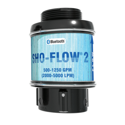
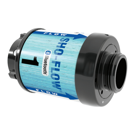
The Sho-Flow water flow indicator is designed for installation behind a nozzle or on the outlet of a pump panel to quickly determine
the flow present in the hose line and the pressure where the Sho-Flow is installed.Any firefighting, training, or testing operation that
utilizes hose lines or nozzles is a potential application for the Sho-Flow. The Sho-Flow will work best if the amount of turbulence
from elbows, valves, wyes, etc. is minimized both downstream and upstream of the unit, as with any flow measuring device.
The Sho-Flow is intended for use with water or solutions of water and foam concentrate. It is not intended for use with pure foam
concentrate, compressed air foam, hydrocarbons or other liquids. The Sho-Flow is not intended for continuous outdoor storage,
because direct sunlight may cause damage to the electronics. Extended storage in hot, or cold environments will shorten battery
life. An arrow indicates the direction of flow. Reverse installation will not damage the flow indicator but incorrect readings will
result.
3.0 SPECIFICATIONS Physical Specifications
Model #’s SF-NF-NF-125
SF-IF-IF-125
SF-BF-BF-475
SF-NF-NF-200
SF-IF-IF-200
SF-BF-BF-750
SF-NF-NF-300
SF-IF-IF-300
SF-BF-BF-11L
SF-NJNJ-500
SF-IJIJ-500
SF-BJBJ-2000
SF-NJNJ-1250
SF-IJIJ-1250
SF-BJBJ-4500
Flow Range 30-125 GPM
100-475 LPM 50-200 GPM
175-750 LPM 70-300 GPM
250-1100 LPM 125-500 GPM
500-2000 LPM 300-1250 GPM
1100-4500 LPM
Standard Inlets
Female 1.5”-9 NH
1.5”-11.5 NPSH
1.5”-11 BSP
1.5”-9 NH
1.5”-11.5 NPSH
1.5”-11 BSP
1.5”-9 NH
1.5”-11.5 NPSH
1.5”-11 BSP
2.5”-7.5 NH
2.5”-8 NPSH
2.5”-11 BSP
2.5”-7.5 NH
2.5”-8 NPSH
2.5”-11 BSP
Standard Outlets
Male 1.5”-9 NH
1.5”-11.5 NPSH
1.5”-11 BSP
1.5”-9 NH
1.5”-11.5 NPSH
1.5”-11 BSP
1.5”-9 NH
1.5”-11.5 NPSH
1.5”-11 BSP
2.5”-7.5 NH
2.5”-8 NPSH
2.5”-11 BSP
2.5”-7.5 NH
2.5”-8 NPSH
2.5”-11 BSP
Weight 2.5 LBS
1.1 KG 2.5 LBS
1.1 KG 2.5 LBS
1.1 KG 4.1 LBS
1.9 KG 4.1 LBS
1.9 KG
Operational Specifications
Flow Accuracy 5% Full Scale Operating Temperature 32-158° F (0-70° C)
Pressure Accuracy 5% Full Scale Storage Temperature -30-185° F (-35-85° C)
Max Operating Pressure 250 PSI (17 BAR) Expected Battery Life 24 Hrs Lithium
10 Hrs Alkaline
Hydrostatic Test Pressure 800 PSI (55 BAR)
Non-recoverable Pressure
Loss @ Max Flow 1250 Model: 15 PSI (1.1 BAR)
All Other Models: 5 PSI (0.5 BAR)
©Copyright Task Force Tips, Inc. 2007-2012 LIS-300 January 26, 2012 Rev05
3
4.0 OPERATION
1) Press ON/MODE button to turn on electronics.
2) Display will toggle between flow and pressure with a red or green light to indicate pressure or flow. Also while displaying flow,
numbers will flash.
3) Pressing the ON/MODE button for ~1 second will lock the display on flow. Pressing again will lock the display on pressure.
Pressing a third time will turn the unit off.
4) Anytime the pressure is less than 5 psi (0.5 bar) for 1 minute, the Sho-Flow flow indicator will automatically turn off.
5) If the display indicates “- - - -“, the flow is too low to be displayed.
6) The 1.5” Sho-Flow may be programmed to give an audible flow warning.
WARNING Kinks in supply hose may reduce water flow and cause injury or death to persons dependant
on water flow. When the SHO-FLOW is attached directly to a fixed supply, it is recommended
that an outlet elbow be used to minimize risk of hoseline kinks.
WARNING The Sho-Flow is not rated for use in explosive atmospheres.
CAUTION The SHO-FLOW must be properly connected. Mismatched or damaged connectors may cause
leaking or uncoupling under pressure and could cause injury.
5.0 FLOW WARNING SET POINT PROGRAMMING - 1.5” VERSION
1) Press and hold the ON/MODE button for 30 seconds. Release when display shows dashes.
2) Adjust water flow to the desired low flow warning level. Display will indicate flow.
3) Press and hold ON/MODE button until (PSI) LED turns on. Release button.
4) (GPM) LED should now be blinking.
5) Adjust water flow to the desired high flow warning level. Display will indicate flow.
6) Press and hold ON/MODE button until (BAR) LED turns on. Release button.
7) Verify that display cycles through low flow and high flow warning set points.
8) Programming is complete.
If flow warning set points are programmed, display will cycle through low flow warning set point and then high flow warning set
point when unit is turned on.
If the flow warning set points are programmed, an alarm will sound during the following conditions:
Low Flow: Water flow is greater than the minimum rated flow of the device and less than the low flow set point
High Flow: Water flow is greater than the high flow set point
6.0 CHANGING BATTERY
When the battery power gets low the display indicates
“LO BATT” but continues to operate until dead.
1) Recommended battery: 9V lithium.
2) Alkaline batteries are acceptable, but battery life is
significantly less.
3) Using #2 Phillips screwdriver loosen screws. Pull lid at
finger pockets to remove.
4) Replace battery.
5) Replace lid, be sure not to pinch wires between lid and
case. Wires cannot be under battery.
6) Turn screws only until contact.
Battery
Compartment
Phillips Drive Screw
Serial Number
Located on Back
©Copyright Task Force Tips, Inc. 2007-2012 LIS-300 January 26, 2012 Rev05
TASK FORCE TIPS, INC.
MADE IN USA • www.tft.com 3701 Innovation Way, Valparaiso, IN 46383-9327 USA
800-348-2686 • 219- 462-6161 • Fax 219-464-7155
7.0 USE WITH SALT WATER
Use with salt water is permissible provided the SHO-FLOW flow indicator is thoroughly cleaned with fresh water after each use. The
service life of the SHO-FLOW may be shortened due to the effects of corrosion and is not covered under warranty.
7.1 CORROSION
All parts of the a SHO-FLOW flow indicator are aluminum hardcoat anodized for corrosion protection. The effects of corrosion can
be minimized by good maintenance practices. See Section 8.0 for maintenance.
8.0 MAINTENANCE
No maintenance is required. No calibration is required under normal circumstances. If unit becomes damaged and does not display
correct data, send it back to the factory for service.
CAUTION Dissimilar metals coupled together can cause galvanic corrosion that can result in the inability
to unscrew the threads or complete loss of thread engagement over time. Per NFPA 1962 (1998
edition), if dissimilar metals are left coupled together an anti-corrosive lubricant should be applied
to the threads. Also the coupling should be disconnected and inspected at least quarterly.
CAUTION Any alterations to the SHO-FLOW flow indicator and its markings could diminish safety and
constitutes a misuse of this product.
9.0 WARRANTY
Task Force Tips, Inc., 3701 Innovation Way, Valparaiso, IN 46383-9327 USA (“TFT”) warrants to the original purchaser of its special
purpose nozzle (“equipment”), and to anyone to whom it is transferred, that the equipment shall be free from defects in material and
workmanship during the five (5) year period from the date of purchase.
TFT’s obligation under this warranty is specifically limited to replacing or repairing the equipment (or its parts) which are shown by
TFT’s examination to be in a defective condition attributable to TFT. To qualify for this limited warranty, the claimant must return the
equipment to TFT, at 3701 Innovation Way, Valparaiso, IN 46383-9327 USA, within a reasonable time after discovery of the defect.
TFT will examine the equipment. If TFT determines that there is a defect attributable to it, TFT will correct the problem within a
reasonable time. If the equipment is covered by this limited warranty, TFT will assume the expenses of repair.
If any defect attributable to TFT under this limited warranty cannot be reasonably cured by repair or replacement, TFT may elect to
refund the purchase price of the equipment, less reasonable depreciation, in complete discharge of its obligations under this limited
warranty. If TFT makes this election, claimant shall return the equipment to TFT free and clear of any liens and encumbrances.
This is a limited warranty. The original purchaser of the equipment, any person to whom it is transferred, and any person who is
an intended or unintended beneficiary of the equipment, shall not be entitled to recover from TFT any consequential or incidental
damages for injury to person and/or property resulting from any defective equipment manufactured or assembled by TFT. It is agreed
and understood that the price stated for the equipment is in part consideration for limiting TFT’s liability. Some states do not allow the
exclusion or limitation of incidental or consequential damages, so the above may not apply to you.
TFT shall have no obligation under this limited warranty if the equipment is, or has been, misused or neglected (including failure to
provide reasonable maintenance) or if there have been accidents to the equipment or if it has been repaired or altered by someone
else.
THIS IS A LIMITED EXPRESS WARRANTY ONLY. TFT EXPRESSLY DISCLAIMS WITH RESPECT TO THE EQUIPMENT ALL
IMPLIEDWARRANTIESOFMERCHANTABILITYANDALLIMPLIEDWARRANTIESOFFITNESSFORAPARTICULARPURPOSE.
THERE IS NO WARRANTY OFANY NATURE MADE BY TFT BEYOND THAT STATED IN THIS DOCUMENT.
This limited warranty gives you specific legal rights, and you may also have other rights which vary from state to state.
This manual suits for next models

14

Other Task Force Tips Measuring Instrument manuals

Task Force Tips SHO-FLOW 1 Installation instructions

Task Force Tips

Task Force Tips SHO-FLOW 1 Installation instructions

Task Force Tips BLITZFIRE Series Installation instructions

Task Force Tips

Task Force Tips BLITZFIRE Series Installation instructions

Task Force Tips MONSOON MONITOR Programming manual

Task Force Tips

Task Force Tips MONSOON MONITOR Programming manual

Task Force Tips YE-RF-900 Guide

Task Force Tips

Task Force Tips YE-RF-900 Guide

Task Force Tips SHO-FLOW Series Quick guide

Task Force Tips

Task Force Tips SHO-FLOW Series Quick guide

Task Force Tips EF1 RC MONITOR Programming manual

Task Force Tips

Task Force Tips EF1 RC MONITOR Programming manual

Task Force Tips SHO-FLOW 1 Quick guide

Task Force Tips

Task Force Tips SHO-FLOW 1 Quick guide

Popular Measuring Instrument manuals by other brands

Lab Unlimited GF500 Operation manual

Lab Unlimited

Lab Unlimited GF500 Operation manual

WAGNER C575 instruction manual

WAGNER

WAGNER C575 instruction manual

DOD Technologies ChemLogic 1 user manual

DOD Technologies

DOD Technologies ChemLogic 1 user manual

Komshine KPM-35 user manual

Komshine

Komshine KPM-35 user manual

Knick Stratos Pro A4..MSPH series instruction manual

Knick

Knick Stratos Pro A4..MSPH series instruction manual

Transducer Techniques SSI Operator's manual

Transducer Techniques

Transducer Techniques SSI Operator's manual

THORLABS PM10-3 Operation manual

THORLABS

THORLABS PM10-3 Operation manual

Acute TravelLogic manual

Acute

Acute TravelLogic manual

ACOEM EVO user manual

ACOEM

ACOEM EVO user manual

Marconi Instruments TF 2337A instruction manual

Marconi Instruments

Marconi Instruments TF 2337A instruction manual

Industrial Fiber Optics IF-RL05 Operator's manual

Industrial Fiber Optics

Industrial Fiber Optics IF-RL05 Operator's manual

Anton Paar EasyDens Instruction Manual and Safety Information

Anton Paar

Anton Paar EasyDens Instruction Manual and Safety Information

Leuze electronic AMS 335i Technical description

Leuze electronic

Leuze electronic AMS 335i Technical description

General DSM402SD user manual

General

General DSM402SD user manual

SPI 20-186-3 Operation manual

SPI

SPI 20-186-3 Operation manual

KROHNE Optisonic 6300 P Short guide

KROHNE

KROHNE Optisonic 6300 P Short guide

Fieldpiece SC680 Operator's manual

Fieldpiece

Fieldpiece SC680 Operator's manual

Campbell CS616 Features

Campbell

Campbell CS616 Features

manuals.online logo
manuals.online logoBrands
  • About & Mission
  • Contact us
  • Privacy Policy
  • Terms and Conditions

Copyright 2025 Manuals.Online. All Rights Reserved.