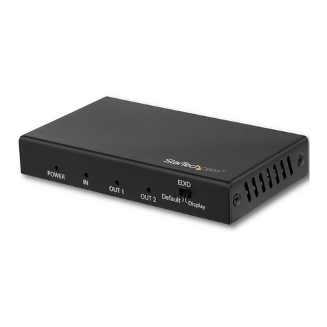
TASKING IEA-DXCPL User manual

DAP over CAN
User Manual
V1.4, June 2023
isystem.com/start

General safety instructions
Please read the following safety precautions carefully before putting this device to use to avoid
any personal injuries, damage to the instrument, or to the target system. Use this instrument
only for its intended purpose as specified by this manual to prevent potential hazards.
Use included power cord and power supply
The enclosed power supply has been approved for use by iSYSTEM. Please contact iSYSTEM if
you need to consider an alternative power.
Use grounding wire
Prior to applying power to either the BlueBox or the target, connect the device and the target
system together with the included grounding wire. This is to avoid potential damage caused by
any voltage difference between the device and the target system.
Use proper overvoltage protection
Ensure proper protection to avoid exposing the BlueBox device or the operator to overvoltage
surges (e.g. caused by thunderstorm, mains power).
Do not operate without cover
Do not operate the device with cover removed.
Avoid circuit and wire exposure
Do not touch exposed components or wires when the device is powered.
Do not operate with suspected damage
If you suspect damage may have occurred, the BlueBox device must be inspected by qualified
service personnel before further operation.
Do not operate the device outside its rated supply voltage or environmental range
Consult with iSYSTEM before using equipment outside of the parameters provided in this
manual.
This symbol is used within the manual to highlight further safety notices.

Contents
Introduction .......................................................................................................................................... 4
Package content ................................................................................................................................ 5
Operation ............................................................................................................................................... 6
winIDEA Configuration ............................................................................................................................ 8
Accessories ............................................................................................................................................ 9

Introduction
DAP over CAN Physical Layer Converter enables debugging via the regular CAN pins of the ECU
connector without opening its housing. This connection is electrically robust due to the nature of
the CAN bus. The DXCPL Converter translates Infineon AURIX™ SPD (Single Pin DAP) encoded DAP
messages to the CAN bus physical layer. iSYSTEM hardware solution supports DXCPL on Infineon
AURIX™ TC2xx and TC3xx devices.
For details about DXCPL operation, refer to Infineon Application Note AP32264.
DAP over CAN Physical Layer Converter can be used with:
·
iC5700 BlueBox via DTM or
·
iC5700 BlueBox via Infineon DAP/DAPE Active Probe or
·
iC5700 BlueBox via Infineon DAP/DAPE II Active Probe or
·
iC5700 BlueBox via Infineon AGBT Active Probe and a 10-pin 1.27 mm DAP Converter
Schematic designer must assure the correct state of TRST signal on cold PORST.

Package content
The DAP over CAN Physical Layer Converter is delivered with the following components:
DAP over CAN
Physical Layer Converter
USB-C cable
Ordering code:
IEA-DXCPL

Operation
Device overview
Device description
A– DAP connector
Pinout valid on the DAP connector side:
Signal
Description
Signal Direction
Signal
Pin
Pin
Signal
Signal Direction
Signal
Description
Reference
voltage
O
Vref
1
2
TXD
I
Transmitter
Ground
GND
3
4
NC
Not Connected
Ground
GND
5
6
RXD
O
Receiver
Not Connected
NC
7
8
NC
Not Connected
Ground
GND
9
10
NC
Not Connected
DAP connector pinout
Signal Direction is described from the BlueBox perspective.
B – DB9 connector
Pinout valid on the DB9 connector side:
Pin
Signal
1
Not Connected
2
CAN_L
3
CAN GND
4
NC
5
SHIELD
6
NC
7
CAN_H
8
NC
9
NC
DB9 connector pinout

C– The LED indicator provides the status of the hardware as follows:
·
Green – Powered on
·
Red – Power supply issue (e.g., burnt fuse)
D– Power supply connection for the Converter. Use provided USB-C cable to power the converter
e.g. from a PC.
CAN 120 Ohm terminating resistor is not implemented on the DAP over CAN Physical Layer
Converter.
iSYSTEM provides cable solutions on request with build in terminating resistor, which can be
easily switched on or off.

winIDEA Configuration
After connecting the hardware follow the steps below to configure the DAP over CAN Physical Layer
Converter in winIDEA:
1. Open Hardware menu / CPU Options.
2. Navigate to the SoC page.
3. Select DXCPL from the Debug channel Mode drop-down.
4. Confirm and establish the debug connection.
Refer to isystem.com/connect for more information on how to connect and configure the hardware.

Accessories
DAP over CAN Physical Layer Converter is used together with the following iSYSTEM hardware:
Description
Ordering Code
iC5700 BlueBox
IC57000
Infineon DAP/DAPE II Active Probe
IC57163-1
Infineon AGBT Active Probe
IC57164
10-pin 1.27 mm DAP Adapter (Infineon AGBT
Active Probe)
IASAM22TRICOREPIN10
1.0m FNet Cable (Active Probe)
BB-FNET-100
2.0m FNet Cable (Active Probe)
BB-FNET-300
5.0m FNet Cable (Active Probe)
BB-FNET-500
1.0m FNet Micro Cable (Active Probe)
BB-FNETMICRO-100
Please refer to the iC5700 BlueBox for all current iC5700 Accessories.
The functionality of the DAP over CAN Physical Layer Converter can be extended through the use of
various accessories.
Ordering Code
Description
IC57040-CAN-DB9
1m CAN cable DB9 plug
IC57040-CAN-PIN
CAN cable pin wires
IC57040-CAN-JACK
CAN cable banana jacks
IC57040-CAN-T
CAN BUS T adapter
More information about our products on www.isystem.com or via sales@isystem.com.

www.isystem.com
Visit our website for:
·
Support - isystem.com/support
·
Tutorials - isystem.com/getting-started
·
Knowledge Base - kb.isystem.com
Table of contents


