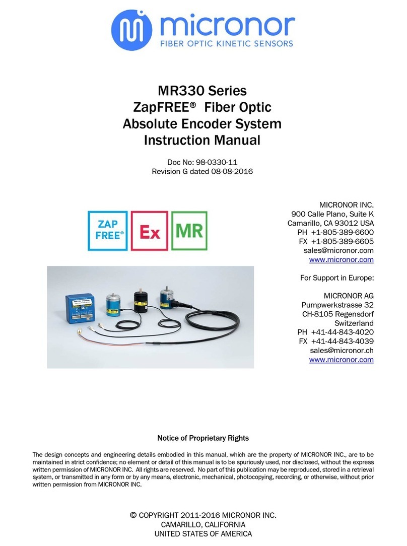
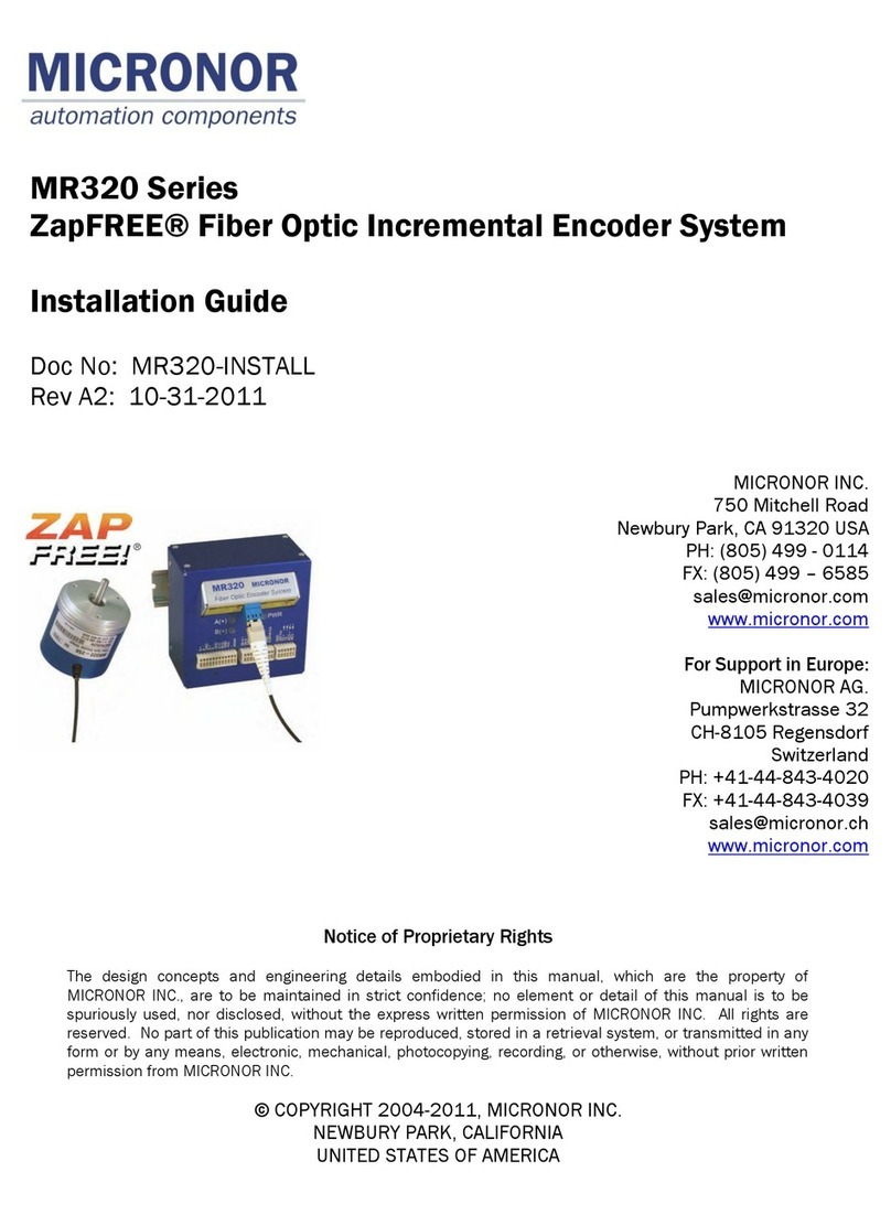
Micronor MR310 Series User manual

MICRONOR INC.
750 Mitchell Road
Newbury Park, CA 91320 USA
PH: (805) 499 - 0114
FX: (805) 499- 6585
www.micronor.com
For support in Europe:
MICRONOR AG.
Pumpwerkstrasse 32
CH-8105 Regensdorf
Switzerland
PH: +41-44-843-4020
FX: +41-44-843-4039
www.micronor.com
Notice of Proprietary Rights
The design concepts and engineering details embodied in this manual, which are the property
of MICRONOR INC., are to be maintained in strict confidence; no element or detail of this
manual is to be spuriously used, nor disclosed, without the express written permission of
MICRONOR INC. All rights are reserved. No part of this publication may be reproduced,
stored in a retrieval system, or transmitted in any form or by any means, electronic,
mechanical, photocopying, recording, or otherwise, without prior written permission from
MICRONOR INC.
© COPYRIGHT 2004-2011, MICRONOR INC.
NEWBURY PARK, CALIFORNIA
UNITED STATES OF AMERICA
MR310/MR320 Series
ZapFREE®
Fiber Optic Encoder System
User Manual
Doc No: MR310-135
Rev: F released 9/7/2011

MICRONOR INC. MR310/MR320 Series ZapFREE® Encoder System
Page 2 of 94
Revision History
Rev X1 Initial Draft
Rev A First Release for use with MR310 PCB RevA and Zappy 1.1
Rev A1 First Release for use with MR310 PCB RevA and Zappy 1.2
Rev B Revision for use with MR310 RevB, MR312 RevA and new MR314 RevA
Rev B1 Minor revisions and typo fixes
Rev C Beginning with MR310 firmware 0.6 and above, MR310 has additional functions
and mode extensions:
Added POSITION mode 2 to Voltage Mode (Register 23) and extended
Voltage Scale setting to 9,000,000 (Register 24, corresponds to range of
internal Position Counter)
Added POSITION modes 3-5 to Current Mode (Register 26) and extended
Current Scale setting to 9,000,000 (Register 27, corresponds to range of
internal Position Counter)
Added Position Counter Reset hardware input via J1/Pin-11 and Position
Reset (signal debounce) mode (Register 29)
Added Quadrature Multiplier mode (Register 2A)
ZAPPY 2.X is compatible with earlier MR310 firmware. When trying to program the
MR310 (using [SAVE TO MR310]), ZAPPY simply returns an error message. Under
serial software control, the MR310 will return an error code.
Rev D Added ATEX and U.S. Hazardous Classifications to Specifications
Added info about low SPEED limitations of analog outputs
Added more info to the error codes section 7.5
Added MR321 Fiber Optic Cleaning Kit to sections 4 and 7.3
Rev D1 Added MR316 Encoder
Added MR312A and MR316A mounting kits to section 5.2
Rev E Additional Functionality with MR310 Firmware Revision 1.18 and up.
Added CURRENT Position Mode 6 (Reg 26)
Added Hardware Preset Value (Reg 2C)
Added Auto Reset On Count (Reg 2D)
Updated ZAPPY™ INSTALLATION SOFTWARE to V3.1
Updated as required to support MR310 V1.18 firmware and new modes
Added [ANALYZE SYSTEM] to DIAGNOSTICS
Rev E1 Added MR318 Encoder
Added MR232-2 USB Adapter cable for running Zappy on a PC without available
serial COM port.
Correction to Specifications and other I/O references:
RESET Input, change from TTL input to PLC-type 24V logic input
A/B Quadrature Outputs, change from Open-Collector to Push-Pull
Rev E2 Corrected diagram for Current Position Mode 3
Added Endface Geometry to ST connector requirements
Rev E3 Added Duty Cycle Adjust (Register 1A)
Updated Parameter default values in ZAPPY™ software
Added updated MR312, MR316 and MR318 Reference Drawings

MICRONOR INC. MR310/MR320 Series ZapFREE® Encoder System
Page 3 of 94
Rev F Added new MR320 Series

MICRONOR INC. MR310/MR320 Series ZapFREE® Encoder System
Page 4 of 94
Table of Contents
1. Product Description............................................................................................... 7
2. Warranty Information ............................................................................................ 9
2.1 Limitations of Warranty .................................................................................. 9
2.2 Contact Information......................................................................................... 9
3. Specifications.......................................................................................................10
3.1 MR310 Series ................................................................................................10
3.1.1 MR310 Controller ...................................................................................10
3.1.2 MR312 Semsor.......................................................................................12
3.1.3 MR314 Sensor ........................................................................................13
3.1.4 MR316 Sensor ........................................................................................14
3.1.5 MR318 MRI Compatible Sensor ............................................................15
3.2 MR320 Series ................................................................................................16
3.2.1 MR320 Controller ...................................................................................16
3.2.2 MR322 Semsor.......................................................................................18
3.2.3 MR324 Sensor ........................................................................................19
3.2.4 MR326 Sensor ........................................................................................20
3.2.5 MR328 MRI Compatible Sensor ............................................................21
4. Initial Preparation................................................................................................22
4.1 Unpacking and Inspection.............................................................................22
4.2 Damage in Shipment ....................................................................................22
4.3 Standard Contents.........................................................................................22
5. Installation Guidelines ........................................................................................23
5.1 System Planning ............................................................................................23
5.2 Mounting the Solid Shaft Encoder Sensors.................................................24
5.3 Mounting the Hollow-Shaft Rotary Encoder ................................................26
5.4 Mounting the Controller Module...................................................................28
5.5 Making Connections to the Controller Module............................................28
5.6 Fiber Optic Cable, Connections and Routing...............................................33
5.7 First Time Start-Up .........................................................................................34
5.8 Manual Gain Calibration (Manual Reset) ....................................................35
5.9 ZAPPY
Installation and Setup Software ...................................................36
5.8.1 Initial Performance Verification with ZAPPY....................................37
6. Operation and Description of Functions...........................................................42
6.1 Block Diagram................................................................................................44
6.2 Firmware Functions and Programming .......................................................46

MICRONOR INC. MR310/MR320 Series ZapFREE® Encoder System
Page 5 of 94
6.2.1 Serial Interface Specification ................................................................46
6.2.2 Communications Protocol .....................................................................46
6.2.3 The Block Check Character <BCC>.......................................................48
6.3 Configuration Commands and Parameters ................................................48
6.3.1 Configuration Commands (Registers 10-19) .......................................50
6.3.2 User Commands (Registers 20-2A) ......................................................51
6.3.3 Diagnostic Commands (Registers 30-39) ............................................53
6.4 Communications/Programming Example ..................................................53
6.5 Detailed Description of Each Function.........................................................55
6.5.1 Counter (Register 20).............................................................................55
6.5.2 Divider (Register 21) ..............................................................................55
6.5.3 RPM (Register 22) ..................................................................................56
6.5.4 Voltage Mode (Register 23)...................................................................56
6.5.5 Voltage Scale (Register 24) ...................................................................58
6.5.6 Voltage Filter (Register 25)....................................................................59
6.5.7 Current Mode (Register 26) ...................................................................60
6.5.8 Current Scale (Register 27) ...................................................................64
6.5.9 Current Filter (Register 28)....................................................................64
6.5.10 Counter Reset (Register 29) ..............................................................65
6.5.11 Counter Multiplier (Register 2A)........................................................66
6.5.12 Encoder Direction (Register 2B) ........................................................67
6.5.13 Hardware Reset Value (Register 2C).................................................68
6.5.14 Reset On Count/Homing (Register 2D) ...........................................69
6.5.15 Saving Parameters in EEPROM (Register 13)..................................70
7. Maintenance and Service ...................................................................................71
7.3 Encoder Will Not Produce Quadrature Signals............................................71
7.1.1 LED’s Do Light Up ...................................................................................71
7.1.2 LED’s Do NOT Light Up ...........................................................................71
7.2 Serial Interface...............................................................................................72
7.2.1 Testing The Interface Cable ...................................................................72
7.3 Fiber Optic Connector Cleaning ....................................................................73
7.3.1 WET Cleaning Method............................................................................74
7.3.2 DRY Cleaning Method - Micronor MR321 DRY Cleaning Kit ..............74
7.4 Troubleshooting .............................................................................................75
7.4.1 Verify MR310 Operation using ZAPPYSoftware ..............................75
7.4.2 Verify Visual Continuity of Fiber Optic Cable Link................................76
7.4.3 Verify Optical Output Power of MR310 Module...................................77
7.4.4 Verify Loss Condition of the Optical Cable Link ...................................77
7.4.5 Built-In System Analysis of Complete Fiber Optic Encoder System and Link
78
7.5 Blinking Error Codes ......................................................................................80
8. Reference Drawings ............................................................................................81

MICRONOR INC. MR310/MR320 Series ZapFREE® Encoder System
Page 6 of 94
List of Figures
Figure 1. Shafted Encoder Face Mount via Counter-Bored Panel............................25
Figure 2. Shafted Encoder Mounting via Thru-Hole With Synchro Clamps..............26
Figure 3. Hollow Shaft Encoder Mounting Options....................................................27
Figure 4. Controller Module Mounted On A DIN Rail. ................................................28
Figure 5. MR310 and MR320 Controllers Have Same Electrical Connections.......30
Figure 6. Cross-Reference for WAGO QuickcConnect Plugs used for J1/J2/J3 Connections
................................................................................................................................31
Figure 7. How To Manual Reset The Controller Module Using WAGO Tool..............31
Figure 8. How To Insert and Remove Wires From the WAGO Plug ...........................32
Figure 9. Inserting/Removing the WAGO Plug From The MR310.............................32
Figure 10. MR320-M06LXX ST Fiber Optic Cable Assembly and MR320A ST
Mating/Bulkhead Adapter....................................................................................33
Figure 11. MR320-D06CXX Duplex LC Fiber Optic Cable Assembly and MR320C Duplex
LC Mating/Bulkhead Adapter..............................................................................33
Figure 12. How to Manually Reset the Controller Module. .......................................35
Figure 13. Photograph of MR232-1 RS422/RS485-to-RS232 Adapter Cable. ......36
Figure 14. HOME Page of ZAPPYSetup Software. ..................................................37
Figure 15. ENCODER Table View Screen via ZAPPYSoftware ...............................38
Figure 16. Initial OPERATE Screen via ZAPPYSoftware.........................................40
Figure 17. Real-time Encoder Operation viewed via OPERATE Screen....................40
Figure 18. DIAGNOSTICS Screen view via ZAPPYSoftware. ..................................41
Figure 19. Online Instructions and Reference Information in INSTRUCTIONS Screen view.
................................................................................................................................41
Figure 20. Block Diagram of the ZapFREE® Fiber Optic Encoder System. .............45
Figure 21. Set-up Parameters for HYPERTERMINAL Program..................................73
Figure 22. Dirty and Clean Fiber Optic Connector Ferrule and Endface Views. ......73
Figure 23. WET Cleaning Method Requires IPA & Dry Wipes OR Pre-Wetted Wipes & Dry
Wipes. ....................................................................................................................74
Figure 24. How To Use the MR321 Kit For Cleaning ST Optical Connectors and Interfaces.
................................................................................................................................75
Figure 25. How To Use the MR321C Kit For Cleaning Duplex LC Optical Connectors and
Interfaces...............................................................................................................75
Figure 26. Verifying Optical Continuity With A Visual Fault Locator. ........................76
Figure 27. Measuring Optical Power Output Of The MR310 Module.......................77
Figure 28. SYSTEM ANALYSIS Screens in ZAPPY™ DIAGNOSTICS Mode ..............79

MICRONOR INC. MR310/MR320 Series ZapFREE® Encoder System
Page 7 of 94
1. Product Description
The MR310/MR320 Series ZapFree® Fiber Optic Rotary Encoders (U.S. Patent 7,196,320) are the
world‟s first totally passive, fiber optic rotary encoder systems –the ideal EMI-immune sensor
solution for all kinds of harsh and hazardous environmental applications. The single fiber MR310
series was introduced in 2004 with the 2nd Generation MR320 series released in 2011.
The ZapFREE® Encoders offer the following features:
All optical, passive sensor does not emit EMI
Immune to EMI, RFI, lightning and ground loops
Interference-free sensor transmission over long distances over a single optical fiber, up to
1000 meters (MR320 can transmit up to 2500 meters)
Industry standard ST-PC optical interconnect (MR320 series uses Duplex LC)
ATEX classified as a "Simple Apparatus" for use in all types of hazardous locations and
explosive atmospheres, including mines and oil rigs
Provides complete electrical isolation between patient and medical instrumentation
Special non-metallic MR318/MR328 sensor for MRI applications
Controller offers multiple built-in interfaces for compatibility with industry standard PLC
interfaces, motor drives and motion control systems
Introduced in 2011, the MR320 series is the 2nd generation of the ZapFREE® Fiber Optic Rotary
Encoder System. To increase optical loss margin and distance, the input and output light paths
(which shared one fiber in the MR310 series) were dedicated to separate fibers with
interconnections based on industry standard Duplex LC. The MR320 series is recommended for
new applications.

MICRONOR INC. MR310/MR320 Series ZapFREE® Encoder System
Page 8 of 94
The MR310/MR320 series offers a wide range of solutions for the motion control engineer:
MR312/MR322 is a Size 58mm shaft encoder with 100/128/256/360ppr options
MR316/MR326 is a Size 90mm shaft encoder with 100/128/256/360ppr options and
IP66 environmental seal for wash down and short immersion.
MR314/MR324 is Size 100mm hollow shaft encoder with 1024ppr resolution
MR318/MR328The single fiber MR310 series was introduced is a non-metallic Size
58mm shaft encoder (360ppr) for MRI and other applications where electromagnetic
transparency is required
STANDARD temperature range is -40°C to +80°C
Optional EXTENDED temperature option operates over -60°C to +150°C
Special harsh environment optical interconnects available as option.
The MR310/MR320 Controller module is the active half and user system interface of the
ZapFREE® Fiber Optic Rotary Encoder System. Over the fiber optic link that connects Sensor and
Controller, the module transmits two optical light sources (850nm and 1300nm) up to the Sensor
and the return path is the chopped return signal from the Sensor. The module's firmware converts
the optical return signals to conventional A/B quadrature outputs as well as other popular
interfaces.
Detailed features of the MR310?MR320 ZapFREE® Controller Modules:
Easily co-located with PLC or motor drive electronics in non-hazardous, control room
environment –allowing actual electrical connections to be simple, short and EMI resistant
Mounts on standard 35mm DIN rail
Operates from readily available +15 to +32VDC power supply
Direct quadrature outputs –both A/B push-pull and A/A‟/B/B‟ line driver
Programmable divider function with dedicated set of quadrature outputs –Line driver
outputs is standard (push-pull is optional)
Two analog outputs (4-20mA and Voltage) are independently programmable and scalable
to output based on SPEED or POSITION
Direct computer control via selectable RS232 or RS485 or USB interface cable
Quick Disconnect Wago Wiring Blocks for efficient wiring
RS232 serial interface can be accomplished with optional MR232-1 Converter Cable
USB interface accomplished with optional MR232-2 Converter Cable

MICRONOR INC. MR310/MR320 Series ZapFREE® Encoder System
Page 9 of 94
2. Warranty Information
MICRONOR INC. warrants this product to be free from defects in material and workmanship for a
period of 1 (one) year from date of shipment. During the warranty period we will, at our option, either
repair or replace any product that proves to be defective. To exercise this warranty, write or call your
local MICRONOR INC. representative, or contact MICRONOR INC. headquarters. You will be given
prompt assistance and return instructions. Send the instrument, transportation prepaid, to the
indicated service facility. Repairs will be made and the instrument returned transportation prepaid.
Repaired products are warranted for the balance of the original warranty period, or at least 90 days.
2.1 Limitations of Warranty
This warranty does not apply to defects resulting from unauthorized modification or misuse of any
product or part. This warranty also does not apply to Fiber Optic Connector interfaces, fuses or AC line
cords.
This warranty is in lieu of all other warranties, expressed or implied, including any implied
warranty of merchantability of fitness for a particular use. MICRONOR INC. shall not be liable for
any indirect, special or consequent damages.
2.2 Contact Information
Micronor Inc.
750 Mitchell Road
Newbury Park, CA 91320
USA
Phone: +1-805-499-0114
Fax: +1-805-499-6585
Email: [email protected]m
URL: www.micronor.com
In Europe:
Micronor AG
Pumpwerkstrasse 32
CH-8015 Regensdorf
Switzerland
Phone: +41-44-843-4020
Fax : +41-44-843-4039
Email: [email protected]h
URL: www.micronor.com

MICRONOR INC. MR310/MR320 Series ZapFREE® Encoder System
Page 10 of 94
3. Specifications
3.1 MR310 Series
3.1.1 MR310 Controller
Functional Specification:
Description
Specification
DIRECT Quadrature Outputs
Bandwidth
Format
Effective with V1.18 Firmware Only:
70 kHz max.
(Contact Micronor concerning modifications for higher bandwidth applications.)
A/A‟/B/B‟ Line Driver and
A/B Push-Pull are Standard
DIVIDER Quadrature Outputs
Divider Range
Format
Programmable DIVIDER range is 2-9999
A/A‟/B/B‟ Line Driver standard
(Push-Pull upon request)
Analog Outputs
Current Output:
Voltage Output:
Each output is individually programmable for POSITION or SPEED.
Range: 0-24mA, Max Burden Resistance: 500(24V supply)
Range: ±12V; Max Current: 5mA (2kload); Short Circuit < 5 sec
POSITION Mode
Internal Counter
Counter Hardware Set-Reset
Full-scale range of selected analog output is 1 to 8,388,607 counts
(equivalent to 8,192 revolutions of MR314 1024ppr encoder) based
on contents of internal counter (Direction/Sign Bit plus 24-bit
counter (8,388,607). Half-step resolution can be achieved by
enabling MULTIPLIER function (x2).
Via PLC-type 24V logic input OR
serial software command
SPEED Mode
Full-scale range of selected analog output can be programmed from
10 to 10,000 RPM
Serial Interface
RS422/RS485
(RS232 with optional MR232-1 adapter cable)
(USB with optional MR232-2 adapter cable)
Fiber Link Length
Up to 1000m (3280ft)
With Maximum 2-Way Optical Loss Budget of 6.5 dB at 850nm
Electrical Connectors
WAGO QuickConnect Plugs:
J1: 12-pin (WAGO 733-112)
J2: 10-pin (WAGO 733-110)
J3: 6-pin (WAGO 733-106)
Power Supply Specifications:
Description
Specification
Power Supply Input
+15VDC to +32VDC, 60mA
(See Note 1)
+5V Output
10mA maximum load
(Designed for powering MR232-1 or MR232-2 adapter cables)
Note 1: During Power Up the external power supply should be capable of delivering a momentary current in excess
of 100mA.

MICRONOR INC. MR310/MR320 Series ZapFREE® Encoder System
Page 11 of 94
Environmental Specifications:
Description
Specification
ATEX Rating
[ Ex op is 55C/T6 ]
“Inherently Safe Optical Radiation”
Temp Range
-5° to +55°C
Humidity
30% to 85% RH (non-condensing)
Sealed
IP40
(Non-Protected)
Physical Dimensions:
Description
Specification
Mounting
35mm DIN Rail
Housing
102mm W x 102mm D x 68mm H
Weight
300g (10.5oz)
Specifications subject to change without notice

MICRONOR INC. MR310/MR320 Series ZapFREE® Encoder System
Page 12 of 94
3.1.2 MR312 Semsor
Functional Specification:
Description
Specification
Resolution
100, 128, 256 or 360 ppr models
Max Speed
8000 rpm (Mechanical Limit)
Optical Interface
Fixed ST Receptacle or Optical pigtail with ST-PC Plug
Fiber Type
MM 62.5/125m, Graded Index, 0.275NA
Fiber Link Length
Up to 1000m (3280ft)
Optical Loss Margin (Max)
6.5dB (Two-way loss margin, MR312 to MR310)
Environmental Specifications:
Description
Specification
Temp Range/ATEX Classification
STANDARD Option
ATEX Rating
U.S. Haz Rating
EXTENDED Option
ATEX Rating
U.S. Haz Rating
“Intrinsically/Inherently Safe Simple Apparatus”
-40° to +80°C
Ex op is I/II 80C/T6
Class I/II/II, AEx op is Group I/II/III 80C/T6 ,
Zone 0/1/2/20/21/22, Division 1/2
-60° to +150°C
Ex op is I/II 150C/T3
Class I/II/II, AEx op is Group I/II/III 150C/T3 ,
Zone 0/1/2/20/21/22, Division 1/2
Humidity
0% to 95% RH (non-condensing)
Seal Rating
IP 64
(Protected against dust, dirt, splashing water. Other IP
protection ratings available upon request.)
Mechanical Specifications:
Description
Specification
Shaft
6mm OD x 5.5mm FLAT x 10mm L
(0.236-in OD x 0.217-in FLAT x 0.393-in L
Max Shaft Loads
Radial = 80N (18 lbf), Axial = 40N (9 lbf)
System MTBF
1.36E+06 hours (155 years)
(Bearing Life calculated at 2,500 RPM and 50% of Maximum
Radial/Axial Shaft Load)
Housing
58mm x 58mm L
Weight
210g (7.25 oz)
Specifications subject to change without notice

MICRONOR INC. MR310/MR320 Series ZapFREE® Encoder System
Page 13 of 94
3.1.3 MR314 Sensor
Functional Specification:
Description
Specification
Resolution
1024 ppr
Max Speed
3000 rpm
(Pulse divider function de-activated. All other functions may be active)
2750rpm
(Speed is limited with all functions activated)
Optical Interface
Optical pigtail with ST-PC Plug
Fiber Type
MM 62.5/125m, Graded Index, 0.275NA
Fiber Link Length
Up to 1000m (3280ft)
Optical Loss Margin (Max)
6.5dB (Two-way loss margin, MR314 to MR310)
Environmental Specifications:
Description
Specification
Temp Range/ATEX Classification
STANDARD Option
EXTENDED Option
“Intrinsically/Inherently Safe Simple Apparatus”
-40° to +80°C
Ex op is I/II 80C/T6
Class I/II/II, AEx op is Group I/II/III 80C/T6 ,
Zone 0/1/2/20/21/22, Division 1/2
-60° to +150°C
Ex op is I/II 150C/T3
Class I/II/II, AEx op is Group I/II/III 150C/T3 ,
Zone 0/1/2/20/21/22, Division 1/2
Humidity
0% to 95% RH (non-condensing)
Sealed
IP 65
(Protected against dust, dirt, splashing water and low pressure
water jets. Other IP protection ratings available upon request.)
Mechanical Specifications:
Description
Specification
Shaft
38mm ID Hollow Shaft Hole
Moment of Inertia
209E-06 kg*m2
System MTBF
1.76E+09 hours (201,061 years)
(Bearing Life calculated at 2,000 RPM)
Housing
100mm x 49mm L
Weight
655g (23 oz)
Specifications subject to change without notice

MICRONOR INC. MR310/MR320 Series ZapFREE® Encoder System
Page 14 of 94
3.1.4 MR316 Sensor
Functional Specification:
Description
Specification
Resolution
100, 128, 256 or 360 ppr models
Max Speed (360ppr)
8,000 rpm(1)
Optical Interface
Fixed ST Receptacle or Optical pigtail with ST-PC Plug
Fiber Type
MM 62.5/125m, Graded Index, 0.275NA
Fiber Link Length
Up to 1000m (3280ft)
Optical Loss Margin (Max)
6.5dB (Two-way loss margin, MR316 to MR310)
Environmental Specifications:
Description
Specification
Temp Range/ATEX Classification
STANDARD Option
ATEX Rating
U.S. Haz Rating
EXTENDED Option
ATEX Rating
U.S. Haz Rating
“Intrinsically/Inherently Safe Simple Apparatus”
-40° to +80°C
Ex op is I/II 80C/T6
Class I/II/II, AEx op is Group I/II/III 80C/T6 ,
Zone 0/1/2/20/21/22, Division 1/2
-60° to +150°C
Ex op is I/II 150C/T3
Class I/II/II, AEx op is Group I/II/III 150C/T3 ,
Zone 0/1/2/20/21/22, Division 1/2
Humidity
0% to 95% RH (non-condensing)
Seal Rating
IP 66
(Protected against dust, dirt, splashing water, low pressure water jets and
temporary immersion. Other IP protection ratings available upon request.)
Mechanical Specifications:
Description
Specification
Shaft
12mm OD x 25mm L with 4x20mm Keyway
(0.236-in OD x 0.217-in FLAT x 0.393-in L
Max Shaft Loads
Radial = 140N (31 lbf), Axial = 70N (15 lbf)
System MTBF
3.11E+05 hours (35.6 years)
(Bearing Life calculated at 2,500 RPM and 50% of Maximum
Radial/Axial Shaft Load)
Housing
90mm x 82.5mm L
Weight
615g (21.5 oz)
Specifications subject to change without notice
Notes: (1) Derate maximum speed by 100rpm per degree Celsius when operating above 60°C.

MICRONOR INC. MR310/MR320 Series ZapFREE® Encoder System
Page 15 of 94
3.1.5 MR318 MRI Compatible Sensor
Functional Specification:
Description
Specification
Resolution
360 ppr
Optical Interface
Optical pigtail with ST-PC Plug, minimum length 5m
(Pigtail length must be long enough so that metallic ST plug is
outside of MRI environment.)
Fiber Type
MM 62.5/125m, Graded Index, 0.275NA
Fiber Link Length
Up to 1000m (3280ft)
Optical Loss Margin (Max)
6.5dB (Two-way loss margin, MR318 to MR310)
Environmental Specifications:
Description
Specification
Temp Range
Ambient laboratory environment
Inherently safe optical radiation, “Simple Apparatus”
Humidity
0% to 95% RH (non-condensing)
Mechanical Specifications:
Description
Specification
Shaft
6mm OD x 5.5mm FLAT x 10mm L
(0.236-in OD x 0.217-in FLAT x 0.393-in L
Housing
58mm x 58mm L
Weight
280g (9.75 oz) - With 5m ST Pigtail)
Specifications subject to change without notice

MICRONOR INC. MR310/MR320 Series ZapFREE® Encoder System
Page 16 of 94
3.2 MR320 Series
3.2.1 MR320 Controller
Functional Specification:
Description
Specification
DIRECT Quadrature Outputs
Bandwidth
Format
70 kHz max.
(Contact Micronor concerning modifications for higher bandwidth applications.)
A/A‟/B/B‟ Line Driver and
A/B Push-Pull are Standard
DIVIDER Quadrature Outputs
Divider Range
Format
Programmable DIVIDER range is 2-9999
A/A‟/B/B‟ Line Driver standard
(Push-Pull upon request)
Analog Outputs
Current Output:
Voltage Output:
Each output is individually programmable for POSITION or SPEED.
Range: 0-24mA, Max Burden Resistance: 500(24V supply)
Range: ±12V; Max Current: 5mA (2kload); Short Circuit < 5 sec
POSITION Mode
Internal Counter
Counter Hardware Set-Reset
Full-scale range of selected analog output is 1 to 8,388,607 counts
(equivalent to 8,192 revolutions of MR314 1024ppr encoder) based
on contents of internal counter (Direction/Sign Bit plus 24-bit
counter (8,388,607). Half-step resolution can be achieved by
enabling MULTIPLIER function (x2).
Via PLC-type 24V logic input OR
serial software command
SPEED Mode
Full-scale range of selected analog output can be programmed from
10 to 10,000 RPM
Serial Interface
RS422/RS485
(RS232 with optional MR232-1 adapter cable)
(USB with optional MR232-2 adapter cable)
Fiber Link Length
Up to or 2500 m (8200 ft)
With Maximum Optical Loss Budget of 12.5 dB at 850nm
Electrical Connectors
WAGO QuickConnect Plugs:
J1: 12-pin (WAGO 733-112)
J2: 10-pin (WAGO 733-110)
J3: 6-pin (WAGO 733-106)
Power Supply Specifications:
Description
Specification
Power Supply Input
+15VDC to +32VDC, 60mA
(See Note 1)
+5V Output
10mA maximum load
(Designed for powering MR232-1 or MR232-2 adapter cables)
Note 1: During Power Up the external power supply should be capable of delivering a momentary current in excess
of 100mA.

MICRONOR INC. MR310/MR320 Series ZapFREE® Encoder System
Page 17 of 94
Environmental Specifications:
Description
Specification
ATEX Rating
[ Ex op is 55C/T6 ]
“Inherently Safe Optical Radiation”
Temp Range
-5° to +55°C
Humidity
30% to 85% RH (non-condensing)
Sealed
IP40
(Non-Protected)
Physical Dimensions:
Description
Specification
Mounting
35mm DIN Rail
Housing
102mm W x 102mm D x 68mm H
Weight
300g (10.5oz)
Specifications subject to change without notice

MICRONOR INC. MR310/MR320 Series ZapFREE® Encoder System
Page 18 of 94
3.2.2 MR322 Semsor
Functional Specification:
Description
Specification
Resolution
100, 128, 256 or 360 ppr models
Max Speed
8000 rpm (Mechanical Limit)
Optical Interface
Fixed ST Receptacle or Optical pigtail with ST-PC Plug
Fiber Type
MM 62.5/125m, Graded Index, 0.275NA
Fiber Link Length
Up to 1000m (3280ft)
Optical Loss Margin (Max)
6.5dB (Two-way loss margin, MR312 to MR310)
Environmental Specifications:
Description
Specification
Temp Range/ATEX Classification
STANDARD Option
ATEX Rating
U.S. Haz Rating
EXTENDED Option
ATEX Rating
U.S. Haz Rating
“Intrinsically/Inherently Safe Simple Apparatus”
-40° to +80°C
Ex op is I/II 80C/T6
Class I/II/II, AEx op is Group I/II/III 80C/T6 ,
Zone 0/1/2/20/21/22, Division 1/2
-60° to +150°C
Ex op is I/II 150C/T3
Class I/II/II, AEx op is Group I/II/III 150C/T3 ,
Zone 0/1/2/20/21/22, Division 1/2
Humidity
0% to 95% RH (non-condensing)
Seal Rating
IP 64
(Protected against dust, dirt, splashing water. Other IP
protection ratings available upon request.)
Mechanical Specifications:
Description
Specification
Shaft
6mm OD x 5.5mm FLAT x 10mm L
(0.236-in OD x 0.217-in FLAT x 0.393-in L
Max Shaft Loads
Radial = 80N (18 lbf), Axial = 40N (9 lbf)
System MTBF
1.36E+06 hours (155 years)
(Bearing Life calculated at 2,500 RPM and 50% of Maximum
Radial/Axial Shaft Load)
Housing
58mm x 58mm L
Weight
210g (7.25 oz)
Specifications subject to change without notice

MICRONOR INC. MR310/MR320 Series ZapFREE® Encoder System
Page 19 of 94
3.2.3 MR324 Sensor
Functional Specification:
Description
Specification
Resolution
1024 ppr
Max Speed
3000 rpm
(Pulse divider function de-activated. All other functions may be active)
2750rpm
(Speed is limited with all functions activated)
Optical Interface
Optical pigtail with ST-PC Plug
Fiber Type
MM 62.5/125m, Graded Index, 0.275NA
Fiber Link Length
Up to 1000m (3280ft)
Optical Loss Margin (Max)
6.5dB (Two-way loss margin, MR314 to MR310)
Environmental Specifications:
Description
Specification
Temp Range/ATEX Classification
STANDARD Option
EXTENDED Option
“Intrinsically/Inherently Safe Simple Apparatus”
-40° to +80°C
Ex op is I/II 80C/T6
Class I/II/II, AEx op is Group I/II/III 80C/T6 ,
Zone 0/1/2/20/21/22, Division 1/2
-60° to +150°C
Ex op is I/II 150C/T3
Class I/II/II, AEx op is Group I/II/III 150C/T3 ,
Zone 0/1/2/20/21/22, Division 1/2
Humidity
0% to 95% RH (non-condensing)
Sealed
IP 65
(Protected against dust, dirt, splashing water and low pressure
water jets. Other IP protection ratings available upon request.)
Mechanical Specifications:
Description
Specification
Shaft
38mm ID Hollow Shaft Hole
Moment of Inertia
209E-06 kg*m2
System MTBF
1.76E+09 hours (201,061 years)
(Bearing Life calculated at 2,000 RPM)
Housing
100mm x 49mm L
Weight
655g (23 oz)
Specifications subject to change without notice

MICRONOR INC. MR310/MR320 Series ZapFREE® Encoder System
Page 20 of 94
3.2.4 MR326 Sensor
Functional Specification:
Description
Specification
Resolution
100, 128, 256 or 360 ppr models
Max Speed (360ppr)
8,000 rpm(1)
Optical Interface
Fixed ST Receptacle or Optical pigtail with ST-PC Plug
Fiber Type
MM 62.5/125m, Graded Index, 0.275NA
Fiber Link Length
Up to 1000m (3280ft)
Optical Loss Margin (Max)
6.5dB (Two-way loss margin, MR316 to MR310)
Environmental Specifications:
Description
Specification
Temp Range/ATEX Classification
STANDARD Option
ATEX Rating
U.S. Haz Rating
EXTENDED Option
ATEX Rating
U.S. Haz Rating
“Intrinsically/Inherently Safe Simple Apparatus”
-40° to +80°C
Ex op is I/II 80C/T6
Class I/II/II, AEx op is Group I/II/III 80C/T6 ,
Zone 0/1/2/20/21/22, Division 1/2
-60° to +150°C
Ex op is I/II 150C/T3
Class I/II/II, AEx op is Group I/II/III 150C/T3 ,
Zone 0/1/2/20/21/22, Division 1/2
Humidity
0% to 95% RH (non-condensing)
Seal Rating
IP 66
(Protected against dust, dirt, splashing water, low pressure water jets and
temporary immersion. Other IP protection ratings available upon request.)
Mechanical Specifications:
Description
Specification
Shaft
12mm OD x 25mm L with 4x20mm Keyway
(0.236-in OD x 0.217-in FLAT x 0.393-in L
Max Shaft Loads
Radial = 140N (31 lbf), Axial = 70N (15 lbf)
System MTBF
3.11E+05 hours (35.6 years)
(Bearing Life calculated at 2,500 RPM and 50% of Maximum
Radial/Axial Shaft Load)
Housing
90mm x 82.5mm L
Weight
615g (21.5 oz)
Specifications subject to change without notice
Notes: (1) Derate maximum speed by 100rpm per degree Celsius when operating above 60°C.
This manual suits for next models
11
Table of contents
Other Micronor Media Converter manuals
Popular Media Converter manuals by other brands

Philips
Philips SWS2102W Specifications

Behringer
Behringer ULTRAGAIN PRO-8 DIGITAL ADA8000 quick start guide

AJA
AJA V2Digital Installation and operation guide

Pepperl+Fuchs
Pepperl+Fuchs ENA TL IO Series manual

Parallax Power Supply
Parallax Power Supply 7300 Series Installation guidelines

Hegel
Hegel HD30 user manual