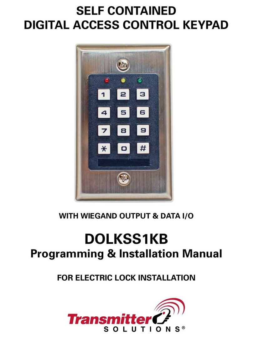
Tate Colson APX-03 User manual

a division of
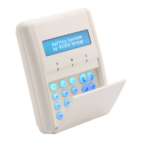
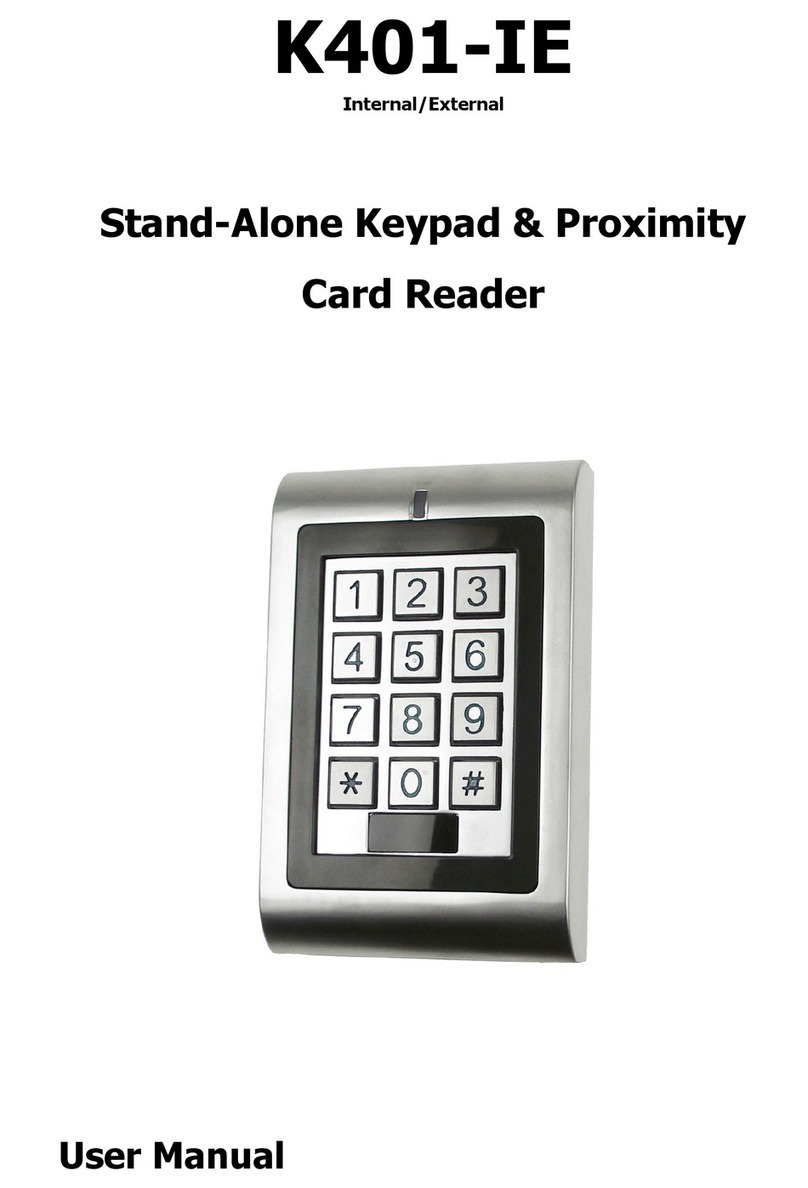
APX-03 Keypad & Proximity Reader
Installation Instructions
Contents:
Page 1. Product overview and Fixing instructions.
Page 2. Wiring detail for Electric Release/Strike - Wiring detail for Magnetic Lock.
Page 3. Wiring detail for Two Magnetic Locks - Wiring detail for Bell/Sounder.
Page 4. Initial Power up procedure - Programming overview - Adding a User Code.
Page 5. Adding a User Fob (Mode 2 User Fob only).
Page 6. Adding a User Fob and 4 Digit Group Code (Mode 3 User Fob + Group code) -
Deleting a Single Fob - Deleting a Group of Fobs (Mode 2 & 3).
Page 7. Restoring a Deleted Fob - Changing Lock open Time & Bell ringing time -
Changing the Master Code.
Page 8. Clearing Code & Fob data (Memory Reset) - Adding a new Master Fob if the
Original is Lost - Specifications.
Page 9&10. System Record Sheet and Fob Name & Number list.
Page 11. Troubleshooting Guide
Head Office: Securefast Plc. Unit 6, Cedar Business Centre, Cannock, Staffs. WS11 1QJ. Tel:01543-501600
Sales & Technical Office: Tate Colson. 1st Floor, Queen Anne House, 18 Eastbank Street, Southport, Merseyside. PR8 1DT. Tel: 01704-502801

APX-03 Keypad & Proximity Reader Installation Instructions
Overview:-
The APX03 Keypad & Proximity Reader is a self contained stand alone unit suitable for Internal or sheltered
External installations in Low risk areas of a building. The unit provides access control for authorised persons allowing entry with
either a valid 4 digit Code, Proximity fob or Proximity fob & common 4 digit Code number.
The unit is programmed by using a Master proximity fob and the 16 button keypad.
Up to five 4 digit Codes can be added and 12,000 Proximity fobs (split into 20 groups of 600). Each group of fobs can also be
allocated a common 4 digit code.
There is also an optional Door Bell button which can be connected to a 12v DC Bell or Sounder.
There are 2 Relay outputs both rated up to 12v DC @ 1amps Max. On the front of the unit there are 3 indication lights which
illuminate during Operation and Programming along with an audible sounder/buzzer.
Important points:-
Installation MUST be done by a Qualified Electrician/Installation Engineer and comply with current Standards & Legislation.
The APX-03 must be connected to a Regulated 12v DC Power Supply with Minimum Load rated @ 1amp.
The Maximum load on either Relay Must Not exeed 1amp (use seperate relay if above 1amp).
The Capacitor 474J 100JS must be fitted accross the Lock connections to protect the Keypad from damage.
Ensure there is a gap of at least 50cm(20") when fitting more than 1 unit to prevent interference.
Before powering up the unit ensure you have read the 'Initial Power Up' instructions and have the lowest number Fob ready.
There are 3 modes of operation:- Mode 1: 4 Digit Code only - Mode 2: Fob only - Mode 3: Fob + 4 Digit Group Code.
When Programming the unit ensure you don't have any Fobs in your hand while pressing the buttons.
The Master Fob MUST be kept in a safe location after installation and Programming is done.
Pre-wired Cable Colour connections:-
RED = 12v DC + Input. BLACK = 12v DC - Input. YELLOW = Lock Relay Common. GREEN = Lock Relay Normally Closed.
BROWN = Lock Relay Normally Open. ORANGE = 2nd Relay Common. PURPLE = 2nd Relay Normally Closed.
GREY = 2nd Relay Normally Open. WHITE = Exit Button trigger. BLUE = Exit Button ground.
Fixing Instructions:-
1. Decide on the position of the keypad taking the following points into consideration:- Keypad must be fixed to a flat and
level surface. The recommended fixing height is 1-1.5 metres from the floor. If fixing more than 1 keypad ensure there is a
gap of at least 50cm(20") to avoid interference. Do NOT fit the Keypad in exposed external or High risk applications.
2. Fix the Surface Box - using the surface box as a template mark the 4 fixing holes and cable entry hole, drill holes and fit
suitable wall plugs and fix using the 4 x 40mm(1.5") screws provided.
3. Position a Regulated 12v DC Power Supply (Min.1A Load) within 20 metres of the Keypad. Fix as per the Manufacturer's
instructions and run a 2 core 1mm2 cable to the Keypad connecting the RED wire to + and BLACK wire to - as shown on
the wiring detail. (DO NOT SWITCH THE POWER ON).
4. Fit the Electronic Locking Device as per the Manufacturer's instructions and run a 2 core 1mm2 cable to the Keypad.
Ensure the Capacitor 474J 100JS is fitted accross the + & - connections at the Lock. Connect Negative of the Lock to the
BLACK wire and Positive to the GREEN wire for Fail Locked or BROWN wire for Fail Unlocked (Only connect one Colour)
also link the YELLOW wire to the RED wire at the keypad as shown on the wiring detail (see Fig 1 or 2 on page 2).
NOTE: Lock must have a current draw of less than 1amp. (see page 3 Fig.3 for wiring a Lock current draw 1amp or over).
5. Exit Button (Optional) - Fit the Exit Button as per the Manufacturer's instructions and run a 2 core 1mm2 cable to the
keypad. Ensure the Common and Normally Open connections are used and connect the BLUE wire to Common and
WHITE wire to Normally Open (see page 2 Fig.1 or Fig.2).
6. Door Bell (Optional) - Fit the Bell/Sounder as per Manufacturer's instructions and run a 2 core 1mm2 cable to the Keypad.
Connect Positive of the Bell/Sounder to the GREY wire and Negative of the sounder to the BLACK wire also link the
ORANGE wire to the RED wire at the keypad as shown on the wiring detail (see page 3 Fig.4).
NOTE: Ensure the Bell/Sounder current draw is less than 1amp.
7. Cut down and Insulate any unused wires and Fix the Keypad/Reader to the surface box using 2 x 16mm(5/8") screws
provided. Fit the Black plastic trim cover onto the front of the unit.
IMPORTANT: Before applying power to the unit you must read and understand the Initial power up instructions on page 4
and ensure you have the Fob with the lowest number ready to be programmed as the Master Fob.
1Web: www.tatecolson.co.uk E-mail:[email protected] Tel: 01704-502801 Fax: 01704-502810

APX-03 Keypad & Proximity Reader Wiring Details
Com N/O
Exit Button
OKOK
11
22 33
FUNFUN
44
55 66
77 88 99
CLRCLR
00
EN
MENUMENU
F
U
S
E
N E L
O/P +
O/P -
Regulated 12v DC Power Supply
(Min 1amp Rated)
Fused Spur
Electric Release
12v DC Fail Lock*
(Max 1amp load)
Capacitor
474J 100JS
APX03 Keypad/Reader
Black - Negative input
Red - Positive input
Blue - Ground
White - RQE
Yellow - Relay 1 Common
Brown - Relay 1 Norm. Open
Green - Relay 1 Norm. Closed*
*For Fail Unlock
version use Green
wire instead
Note: Violet, Orange and
Grey wires are not used
Fig.1 - Wiring detail for Electric Release including Exit Button
Link the Yellow wire
to the Red wire
Com N/O
Exit Button
OKOK
11
22 33
FUNFUN
44
55 66
77 88 99
CLRCLR
00
EN
MENUMENU
F
U
S
E
N E L
O/P +
O/P -
Regulated 12v DC Power Supply
(Min 1amp Rated)
Fused Spur
Capacitor
474J 100JS
APX03 Keypad/Reader
Black - Negative input
Red - Positive input
Blue - Ground
White - RQE
Yellow - Relay 1 Common
Brown - Relay 1 Norm. Open
Green - Relay 1 Norm. Closed
Note: Violet, Orange and
Grey wires are not used
+
-
Magnetic Lock 12v DC
Maximum 1amp load
Com N/C
Emergency
Call Point
Fig.2 - Wiring detail for Magnetic Lock including Exit Button and Call Point
Link the Yellow wire
to the Red wire
2

APX-03 Keypad & Proximity Reader Wiring Details
Fig.3 - Wiring detail for Electric Lock with Current Draw 1amp or over
EG: Two Magnetic Locks including Exit Button and Call Point
N/C
COM
N/O
Com N/O
Exit Button
OKOK
11
22 33
FUNFUN
44
55 66
77 88 99
CLRCLR
00
EN
MENUMENU
F
U
S
E
N E L
O/P +
O/P -
Regulated 12v DC Power Supply
(Min 2amp Rated)
Fused Spur
Capacitor
474J 100JS
APX03 Keypad/Reader
Black - Negative input
Red - Positive input
Blue - Ground
White - RQE
Yellow - Relay 1 Common
Brown - Relay 1 Norm. Open
Green - Relay 1 Norm. Closed
Note: Violet, Orange and
Grey wires are not used
+
-
Magnetic Locks 12v DC
Com N/C
Emergency
Call Point
Volt-Free Relay
+
-
Note: Linking wiring from
one magnet to the other
will affect Holding force.
Note: This wiring method can also be
used for Shear Magnets or Solenoid Bolts
OKOK
11
22 33
FUNFUN
44
55 66
77 88 99
CLRCLR
00
EN
MENUMENU
+-
12v DC
Bell / Sounder
(Max 100mA)
F
U
S
E
N E L
O/P +
O/P -
Regulated 12v DC Power Supply (Min 1amp)
Fused Spur
Fig.4 - Wiring detail for Connection of a 12v DC Bell or Sounder
Grey - Relay 2 Normally open
Orange - Relay 2 Common
Red - Positive Input
Black - Negative Input
Link Orange wire
to Red wire
3Web: www.tatecolson.co.uk E-mail:[email protected] Tel: 01704-502801 Fax: 01704-502810
Remember to link the
Yellow wire to the
Red wire
+
-

APX-03 Keypad & Proximity Reader Programming Instructions
Initial Power up
On initial power up of the Keypad the Error, OK and Power indicators will light up. Wait for 3 long Bleeps, then a
short Bleep followed by the Error and OK lights flashing. Within 10 seconds present the Fob you want to set as
the "Master" in front of the buttons. A long bleep will sound to confirm the Fob is programmed as the "Master".
Important Note: The Fob with the lowest number must be used as the "Master" Fob and clearly marked as
"MASTER" . It must also be kept in a safe place for future use after the system is Programmed.
If the Master Fob is lost you will have to add a new one as shown on page 8. If the keypad does not respond
with 3 bleeps you will need to follow instructions for Adding a Master fob when original is lost as shown on page 8.
OK
Key to Indicators: = Error. = OK. = Power.
The APX03 Keypad can be programmed to operate in 3 different modes:-
Mode 1 - 4 Digit Code only Mode 2 - Fob only Mode 3 - Fob + 4 Digit Group Code
Any or all three of the above modes can be used at the same time as long as the Fobs for mode 3 are set in to a
different Group to the Fobs for mode 2. When Fobs are added they must be programmed as a group of consecutive
numbers. If you have several batches of consecutive numbered Fobs each batch must be programmed into a
different Group number. Ensure the Codes and Fob numbers are written on the System Record Sheet (Page 9&10)
Important Note: When pressing the buttons during programming ensure you do not have any Fobs in your
hand or within 15cm of the Keypad as this will not allow the unit to be programmed correctly.
If the wrong information is entered the Error indicator will flash once along with a low tone bleep then the
keypad will return to the beginning of programming and the Power indicator will flash. Re-enter the
Function code number and continue to enter the programming information.
Note: Before any programming can be done you must put the keypad into Programming Mode:-
Example Indication
1 Enter Function code 2 then EN
FUN 2 EN
Error and OK indicators flash
2 Present Master Fob
Present Master Fob
Short Bleep and OK indicator flashes
3 Enter Master code then EN
1234 EN
Long bleep and Power indicator flashes
Note: The Default Master Code is 1234. We recommend this is changed after programming (see page 7).
To Enter programming mode:
MODE 1 - 4 Digit User Code only - Up to 5 Codes can be programmed
Note: To Delete a User code follow above programming but enter "0000" instead of the user code.
Example Indication
1
2 Enter Function code 46 then EN
FUN 46 EN
OK indicator flashes
3 Enter Slot No.(01 to 05) then EN
01 EN
OK indicator flashes
4 Enter new 4 digit User Code then EN:
4321 EN
OK indicator flashes
5 Re-Enter new User Code then EN:
4321 EN
Long Bleep and Power indicator flashes
6 Exit Programming Mode:
FUN 2 EN
Long Bleep and OK indicator flashes once
Enter into Programming mode as above
To Add a 4 Digit User code:
Code Operation: To use the code press CLR button (OK indicator flashes) - enter 4 digit code then EN.
Example: CLR - 4321 - EN. If the code is correct the OK indicator will flash once. If code is incorrect a short
tone will sound and the Error indicator will flash once.
4

APX-03 Keypad & Proximity Reader Programming Instructions
MODE 2 - User Fob only
Note: The Keypad will hold up to 12,000 user Fobs which are split up into 20 Groups of 600 Fobs.
Each group of Fobs must be numbered consecutively. Fobs can be programmed by number or by presenting the
lowest number Fob then the highest number Fob. If you have several batches of Fobs each batch must be
entered into a different Group number.
Example Indication
1
2 Enter Function code 31 then EN
FUN 31 EN
OK indicator flashes
3 Enter option 0 then EN
0 EN
OK indicator flashes
4 Enter Group Number (01 to 20) then EN
01 EN
OK indicator flashes
5 Enter the lowest 10 Digit Fob number
0001234567 EN
2 Bleeps and OK indicator flashes to confirm
6 Enter the highest 10 Digit Fob number
0001234616 EN
Double Bleep and Power indicator flashes
7 Exit Programming Mode:
FUN 2 EN
Long Bleep and OK indicator flashes once
To Add a Group of Fobs by Fob No:
Enter into Programming mode as shown on page 4.
Example Indication
1
2 Enter Function code 31 then EN
FUN 31 EN
OK indicator flashes
3 Enter option 1 then EN
1 EN
OK indicator flashes
4 Enter Group Number (01 to 20) then EN
01 EN
Error and OK indicators start flashing
5When indicators start flashing present
lowest number Fob in front of buttons
Present Lowest Fob
Short Bleep & OK indicator flashes once
6When indicators start flashing present
highest number Fob in front of buttons
Present Highest Fob
Long Bleep and Power indicator flashes
7 Exit Programming Mode:
FUN 2 EN
Long Bleep and OK indicator flashes once
To Add a Group of Fobs using Fob:
Enter into Programming mode as shown on page 4.
Fob Operation: To use the Fob simply hold in front of the buttons within 7cm. If Accepted you will hear a
short Bleep & OK will Flash. If Rejected you will hear a long Bleep & Error will flash once.
5Web: www.tatecolson.co.uk E-mail:[email protected] Tel: 01704-502801 Fax: 01704-502810

APX-03 Keypad & Proximity Reader Programming Instructions
MODE 3 - User Fob + 4 Digit Group code
Mode 3 provides more security by allocating a group of user Fobs with a common 4 digit code which has to be
entered after the Fob is recognised by the Keypad. When adding the batch of Fobs they must be programmed
into a different group from those being used for Fob only access (Mode 2).
You must Program the Fobs first before programming the Common Group code.
First Program the batch of Fobs as per Mode 2 but use a different Group number (see page 5)
Example Indication
1
2 Enter Function code 45 then EN
FUN 45 EN
OK indicator flashes
3 Enter Fobs Group No (01 to 20) then EN
01 EN
OK indicator flashes
4 Enter New 4 Digit Group code then EN
5678 EN
OK indicator flashes
5 Re-Enter New 4 Digit Code then EN
5678 EN
Long Bleep and OK indicator flashes
6 Exit Programming Mode:
FUN 2 EN
Long Bleep and OK indicator flashes
Important Note: The Group Code will now have to be entered after the Fob is presented.
Enter into Programming mode as shown on page 4.
To Add a 4 Digit Group Code for
Fob+Code entry:
Note: To Delete a Group code follow the above programming but enter "0000" instead of the Group code.
When a Group code is deleted the Fobs will revert to Fob only (Mode 2) operation.
Fob+Code Operation: Hold the fob in front of the buttons within 7cm, keypad will bleep and OK will start to flash.
Enter the 4 digit Group code then EN. If Accepted OK will flash. If code is Rejected you will hear a long Bleep
and Error will flash. Re-Enter using the correct code
MODE 2 & MODE 3 - Deleting Fobs
Example Indication
1
Enter into Programming mode as shown on page 4.
2 Enter Function code 33 then EN
FUN 33 EN
OK indicator flashes
3 Enter option 0 then EN
0 EN
OK indicator flashes
6 Enter the 10 Digit Fob number then EN
0001234567 EN
Long Bleep and Power indicator flashes
7 Exit Programming Mode:
FUN 2 EN
Long Bleep and OK indicator flashes once
To Delete a single Fob by Number:
Example Indication
1
2 Enter Function code 32 then EN
FUN 32 EN
OK indicator flashes
3 Enter Group Number (01 to 20) then EN
01 EN
OK indicator flashes
4 Exit Programming Mode:
FUN 2 EN
Long Bleep and OK indicator flashes once
To Delete a Group of Fobs by Fob
Number:
Enter into Programming mode as shown on page 4.
6

APX-03 Keypad & Proximity Reader Programming Instructions
MODE 2 & MODE 3 - Restoring a Deleted Fob
Example Indication
1
2 Enter Function code 34 then EN
FUN 34 EN
Error and OK indicators start flashing
3When indicators start flashing present
deleted Fob in front of buttons
Present Fob
Long Bleep and Power indicator flashes
4 Exit Programming Mode:
FUN 2 EN
Long Bleep and OK indicator flashes once
To Restore a Deleted Fob:
Enter into Programming mode as shown on page 4.
The Fob will now be restored back into the original Group it was programmed into.
Note: If the Group it was programmed into has been deleted you will not be able to restore the Fob until the
Group is reprogrammed.
Additional Programming functions
Example Indication
1
Enter into Programming mode as shown on page 4.
2 Enter Function code 62 then EN
FUN 62 EN
OK indicator flashes
3 Enter Relay 1 then EN
1 EN
OK indicator flashes
4 Enter Lock release 1 then EN
1 EN
OK indicator flashes
5Enter the number of Seconds (001-250)
then EN
005 EN
Long Bleep and Power indicator flashes
6 Exit Programming Mode:
FUN 2 EN
Long Bleep and OK indicator flashes once
To Change Lock open time:
Note: The number of seconds must be entered as 3 digits. I.E.: 5 Seconds = 005, 10 Seconds = 010 etc.
Example Indication
1
Enter into Programming mode as shown on page 4.
2 Enter Function code 62 then EN
FUN 62 EN
OK indicator flashes
3 Enter Relay 2 then EN
2 EN
OK indicator flashes
4 Enter Door Bell 2 then EN
2 EN
OK indicator flashes
5Enter the number of Seconds (001-250)
then EN
005 EN
Long Bleep and Power indicator flashes
6 Exit Programming Mode:
FUN 2 EN
Long Bleep and OK indicator flashes once
To Change Door bell ringing time:
Note: The number of seconds must be entered as 3 digits. I.E.: 5 Seconds = 005, 10 Seconds = 010 etc.
Example Indication
1
Enter into Programming mode as shown on page 4.
2 Enter Function code 41 then EN
FUN 41 EN
OK indicator flashes
3 Enter New 4 Digit Master code
2580 EN
OK indicator flashes
4 Re-Enter New 4 Digit Master code
2580 EN
Long Bleep and Power indicator flashes
5 Exit Programming Mode:
FUN 2 EN
Long Bleep and OK indicator flashes once
To change the Master code:
7Web: www.tatecolson.co.uk E-mail:[email protected] Tel: 01704-502801 Fax: 01704-502810

APX-03 Keypad & Proximity Reader Programming Instructions
Additional Programming functions
Example Indication
1
Enter into Programming mode as shown on page 4.
2 Enter Function code 48 then EN
FUN 48 EN
OK indicator flashes
3 Enter 0 then EN to clear data
0 EN
Bleep followed by several chirps
To Clear all Code & Fob data:
After a few seconds the keypad will go into the Initial Power up sequence so you will need to re-program the
Lowest Fob number as the Master Fob again (see Initial Power up). All Code & Fob data is now deleted.
8
CARD TYPE EM
FREQUENCY 125KHz
MAXIMUM FOB READING RANGE 110mm
MAXIMUM NUMBER OF FOBS 12,000 (20 BATCHES OF 600 CONSECUTIVE No'S)
MAXIMUM NUMBER OF CODES FIVE 4 DIGIT USER CODES
NUMBER OF DOORS ONE
DIGITAL OUTPUTS TWO VOLTAGE FREE RELAYS (Max 24v DC @ 1A)
INDICATION 3 LIGHTS (POWER / OK / ERROR)
BACKLIGHTING ALL BUTTONS (GREEN)
HOUSING MATERIAL PC + ABS
OPERATING TEMPERATURE -20 deg C to 55 deg C
STORAGE TEMPERATURE -25 deg C to 85 deg C
POWER REQUIREMENTS 12 Volts DC +/- 10% (Min 300mA)
LOCK SUPPRESSION DEVICE CAPACITOR 474J 100JS
DIMENSIONS Width 81mm x Height 123mm x Depth 21mm
SPECIFICATIONS:-
Instructions for Adding a Master Fob when original Master Fob is Lost
To Program a new Master Fob when the original has been lost you will need to remove the Front Cover of the
Keypad and look for a label in the top right corner showing an 8 digit number (if there is no label you will need to
remove the unit from the wall and look on the back for a label with a Barcode and 12 digit serial number).
Make a note of the 5th to 8th numbers (4 digits). Note: All other Code and Fob data will remain the same.
Indication
1 Power indicator will go out
2All 3 indicators flash once then Power indicator
lights followed by a Long Bleep then Short Bleep.
3 OK indicator will start flashing
4All 3 indicators will light up followed by 2 Long
Bleeps then a Short Bleep.
5 Long Bleep and OK indicator flashes once
Note: When adding a New Master Fob we recommend the next lowest number fob is used.
Enter the 4 digit number from the Keypad label then EN
When the Error & OK lights start flashing present the Fob you
want to add as a New Master Fob within 10 seconds.
To Add a New Master Fob when Original is Lost:
Switch the Power Off to the Keypad for 30 Seconds.
Switch Power on and wait for the Keypad to respond
Immediately after the Short Bleep enter MENU then EN

9
APX03 KEYPAD/PROXIMITY READER - SYSTEM RECORD SHEET
Note: Master fob must be lowest fob number SLOT 01 SLOT 04
SLOT 02 SLOT 05
SLOT 03
GROUP No: FIRST FOB No: LAST FOB No: GROUP No: FIRST FOB No: LAST FOB No:
GROUP 01 GROUP 11
GROUP 02 GROUP 12
GROUP 03 GROUP 13
GROUP 04 GROUP 14
GROUP 05 GROUP 15
GROUP 06 GROUP 16
GROUP 07 GROUP 17
GROUP 08 GROUP 18
GROUP 09 GROUP 19
GROUP 10 GROUP 20
FOB No: FOB No:
UNIT LOCATION: DATE INSTALLED:
INSTALLED BY: INSTALL ENGINEER:
MASTER FOB No: USER CODES (4 DIGIT)
MASTER CODE:
NAME:
FOB GROUP SLOT NUMBERS
FOB NUMBER & NAME LIST
NAME:

10
FOB No: FOB No: NAME:
FOB NUMBER & NAME LIST (CONT'D)
NAME:
Photocopy this sheet if required

11
APX-03 Keypad/Proximity Reader - Troubleshooting Guide
For Technical Support call 01704-502815. Monday to Thursday 8.30am - 5pm, Friday 8.30am - 4pm
Fault / Problem Reason / Action required
Power light is not illuminated
Check input voltage is 12v DC (+/- 10%) at RED & BLACK wires.
Make sure Positive is connected to RED & Negative connected to BLACK.
Check the Power unit is 12v DC Regulated with Minimum 1 Amp load.
Power light is permanently illuminated
This is normal and shows the Keypad is in standby mode.
Electronic Lock is not unlocking
Check the YELLOW wire is linked to RED or Positive output of PSU.
Check the voltage at the lock connections is 11-13v DC when the Relay
activates.
Check the correct colour wire is used to suit the lock function - see wiring
detail on page 2 (Fig 1 or 2).
Check Current draw of lock is less than 1amp. A Lock that has a current
draw of 1amp or over should be connected as wiring detail on page 3 Fig.3.
Electronic Lock is permanently Unlocked
Check the Exit button Connections are COM & N/O and check that the
Button is not stuck or jammed.
If no Exit Button is fitted check the BLUE & WHITE wires are not shorted out.
Check the correct colour wire is used to suit the lock function see wiring
detail on page 2 (Fig.1 or 2).
If an Emergency Call point is fitted check if it has been activated and reset.
Bell button does not activate the Bell/Sounder
Check the ORANGE wire is linked to RED or Positive.
Check the voltage at the Bell connections is 11-13v DC when the Relay
activates.
Re-program the Door Bell ringing time (see page 7).
Master Fob does not work after Initial Power up
Make sure you have entered "FUN - 2 - EN" before you presented the
Master Fob.
If after entering "FUN-2-EN" the error indicator flashes when the Master Fob
is presented this shows it is not programmed.
You will need to follow the Adding a New Master Fob instructions on page 8.
Lock does not open when I use my 4 Digit code
Make sure you press "CLR" before the 4 Digit code and "EN" after the
code. (Note: The OK indicator should flash after
"
CLR" is pressed)
If the OK indicator does not flash after "CLR" is pressed it means a 4 Digit
code has not been programmed. Re-Enter the 4 digit code as per page 4.
Check the lock is wired correctly as per wiring detail on page 2 (Fig.1 or 2).
Lock does not open when I use my Fob
If the ERROR indicator and a low bleep sounds the Fob is not programmed,
Delete the Group of Fobs as per page 6 then Re-Program as per page 5.
If the Fob still won't work after the above it may have been deleted as a
single fob. Restore the deleted Fob as shown on page 7.
If the Fob is presented and neither the ERROR or OK indicator responds
the Fob's memory chip may be corrupted. Replace with a new Fob.
Check the lock is wired correctly as per wiring detail on page 2 (Fig.1 or 2).
The ERROR indicator came on during programming and
This means the wrong information has been entered.
now the POWER indicator is flashing
The Keypad has returned to the start of programming so you will need to
Re-Enter the Function code and all the information again.
I have 2 Keypads close together and they are not working
If the Keypads are close together they will cause interference which
prevents them from operating correctly. Power down both units and move
the keypads apart so there is a gap of at least 50cm(20") between them.
I have lost my Master Fob, how do I program keypad
If you loose the Master Fob the next lowest fob will need to be programmed as
the new Master Fob (see Adding a New Master Fob instructions on page 8.
The Keypad will not respond to Codes or Fobs
Power down the keypad and leave for 3 minutes then re-apply the power
and try the Codes or Fobs again.
If the keypad does not respond again check the Capacitor is fitted to the lock
connections and replace if damaged. Power down again as above.
If you experience any problem or fault which is not resolved after reading the above contact Technical Support
Table of contents

