Crow Runner Series User manual

ELECTRONICENGINEERING LTD.
Runner Series
WIRELESSAND WIRED CONTROL PANEL
User’sGuide
Covers:
Runner(NewLook)LED Keypad
&
Runner(NewLook)LCD Keypad
(Coming Soon)
Rev: C G.T. (Updated) April 2008

Crow LimitedWarranty
(Crow) warrants this product tobefree from defects in materials andworkmanshipunder normal use andservice
for aperiodof one year from the last dayof the weekandyear whose numbers are printedon the printedcircuit
boardinside his product.
Crow’s obligation is limitedto repairingor replacingthis product, at itsoption, free of charge for materials or labor,
if it is provedtobedefectivein materialsorworkmanshipunder normal use andservice. Crow shall haveno
obligation under this LimitedWarrantyor otherwise if the product is alteredor improperlyrepairedor servicedby
anyone other then Crow.
There are no warranties, expressedor implied,of merchantabilityor fitnessfor aparticular purpose or otherwise,
which extendbeyondthe description on the face hereof.Inno case shall Crow beliable to anyone for any
consequential orincidental damages for breach of thisor anyother warranty,expressedor implied,or upon any
other basis of liabilitywhatsoever, even if the loss or damage is causedby Crow’s own negligence or fault.
Crow does notrepresent that this productcan notbecompromisedor circumvented;that this product will prevent
anyperson injuryor propertyloss or damageby burglary,robbery,fire or otherwise; or that this product will in all
cases provideadequate warningor protection.Purchaserunderstandsthataproperlyinstalledandmaintained
product can onlyreduce the riskof burglary, robberyor other events occurringwithout providingan alarm, but it is
not insurance or aguarantee that suchwillnot occurorthat there willbenopersonal injuryor propertylossor
damageas aresult. Consequently,Crowshallhaveno liabilityfor anypersonalinjury,propertydamageor any
other lossbasedonclaimthatthisproduct failedtogiveanywarning.However, ifCrowisheldliable, whether
directlyor indirectly,foranylossordamagearisingunder this limitedwarrantyor otherwise, regardlessof cause
or origin, Crow’s maximum liabilityshallnot in anycase exceedthe purchase price of this product, whichshall be
the complete andexclusive remedy against Crow.
© 2005. Allrights reserved.
Information in this document is subject to change without notice. No part of this document maybe reproducedor
transmittedin anyform or by anymeans, electronic or mechanical, without express written permission of
Printversion 002

i
Contents
INTRODUCTION...................................................................................................................................1
THE CROW ALARM CONTROL SYSTEM.......................................................................................................1
TYPICAL ALARM SYSTEM CONFIGURATION..................................................................................................1
KEYPAD DESCRIPTION........................................................................................................................2
FUNCTION KEYS.................................................................................................................................2
ALPHANUMERIC KEYS ..........................................................................................................................2
AUDIBLE SIGNALS ..............................................................................................................................2
INDICATORS .....................................................................................................................................3
SUMMARYOF FUNCTIONS .....................................................................................................................3
OPERATING THE KEYPAD....................................................................................................................4
HOW TO ARMTHE SYSTEM BEFORE EXIT ...................................................................................................4
Preparing the System forArming.......................................................................................................4
Arming the System............................................................................................................................4
Quick Arm (When enabled atinstallation)..........................................................................................4
Disarming the System.......................................................................................................................4
Stopping and Resetting Alarms..........................................................................................................4
ARMINGTHE SYSTEM WHILE STAYING HOME..............................................................................................5
Arming the System inStayMode.......................................................................................................5
Disarming the System.......................................................................................................................5
HOW TO ARM PARTITIONS ....................................................................................................................5
HOW TO BYPASS ZONES.......................................................................................................................5
USING CHIME (IF ENABLED AT INSTALLATION)............................................................................................6
EMERGENCY ALERTS............................................................................................................................6
Howto initiate Panic..........................................................................................................................6
Howto initiate Medical Alarm.............................................................................................................6
Howto initiate Fire Alarm...................................................................................................................6
GENERATE THREATOR DURESS ..............................................................................................................6
HOW TO READ LED INDICATIONS ...........................................................................................................7
HOW TO READ SYSTEM MESSAGES ..........................................................................................................8
HOW TO READ TROUBLE MESSAGES.........................................................................................................8
HOW TO DISPLAY EVENTS FROM MEMORY .................................................................................................8
HOW TO CONTROL OUTPUTSAND DEVICES ..............................................................................................12
ENTERINGTHE USER PROGRAM/CLIENT MODE ..........................................................................................12
HOW TO CHANGEOR ADD CODES .........................................................................................................12
About Master Code and the User Code...........................................................................................12
Howto Change the Master Code.....................................................................................................13
Howto Add or Change a User Code (other than the Master Code)..................................................13
Howto Delete the User Code (ItisAdvisableto Change a code and Not delete it)...........................13
ADDING/CHANGING TELEPHONE NUMBERS...............................................................................................13
HOW TOSET TIMEAND DATE ..............................................................................................................14
HOW TO OPERATE THE ACCESS CONTROL OUTPUT .....................................................................................14
HOW TOSTART WALK TEST MODE ........................................................................................................14
HOW TO ANSWERAN IN-COMING CALL...................................................................................................14

Contents
ii
USING THE REMOTE COMMAND CONTROL ................................................................................................15
USING LOCAL COMMAND CONTROL........................................................................................................16
LCD KEYPAD.......................................................................................................................................17
ADJUSTING BACKLIGHTING AND BUZZER TONE ..........................................................................................17
LCD KEYPAD IN LOCAL EDIT MODE .......................................................................................................18
Accessing LocalEdit Mode..............................................................................................................18
LocalEditMode DirectProgramAddresses.....................................................................................18
LCD KEYPAD LOCAL EDIT MODE MENU PROGRAMMING....................................................................19
Changing the Area SingleCharacter Identifier.................................................................................21
Changing the Zone Names..............................................................................................................21
Changing the Keypad Area Name...................................................................................................22
Changing the Keypad Name............................................................................................................22
Changing the User Names..............................................................................................................22
Changing the Output Names...........................................................................................................22
Resetting Individual Text to Default orLast SavedSetting...............................................................23
Resetting All Text toDefault............................................................................................................23
Copying Text toanother LCD Keypad..............................................................................................23
Exiting LocalEditProgram Mode.....................................................................................................23
CUSTOMIZATION CHART...................................................................................................................24

1
Introduction
TheCrow Alarm ControlSystem
Weare really pleased that you chose to protect your premises andpossibly even your lives with
our RUNNER SERIES from Crow Electronic Engineering Ltd.
The RUNNERSERIES is a highly advanced,multifunction alarm controlsystem,designed to
flawlessly manageyour securitysystem at homeor at business,protects you against burglary
and supports the operation of multipleelectronic devices.
The RUNNER SERIES has manyincredible program options and additionalaccessories that can
enhance the standard features of the panel from simple “HomeAutomation” to “Radiocontrol”
and VoicePrompted Command control”.Please askyour installer to find out more about these
powerfulfeatures.
You can phone your home to check or changethe status of any output using the keys on your
phone.Arm or disarm the whole house or just onearea,allwith your own voice confirming your
selections.
Imagine turning on the spa before leaving work soit is hot when you getin the door.The under-
floor heating hasjust automatically switched on usingthe on boardtimer and you have just
openedthe roller-door and disarmed the garage from your cellphone so thewhite ware
repairman can work on your washer.
The controller supports a 16 LED keypad or the more sophisticated LCD (liquidCrystal Display)
keypad.
It also has a comprehensive alarm event memory that logs allcontroller activity with a time and
date stamp.
TypicalAlarm System Configuration
The protected premises can be divided up into 16 zones,as defined by theinstallation scheme.
The protected area can begrouped into two separate partitions (A and B).
The system enables you in a business environment,to conveniently group separately,the offices
from the warehouse area,orin a private residence,thedifferent rooms of the home.For
example,living room,bedroom,and maybe the basement and attic.
These groups or zones can reactspecifically to different types of events and then generating an
alarm or activate a device.
The system can be armed intwo different modes:
Arm – the protected areas are entirelyvacated.
Stay – people and pets populate the protected areas.
You have access to thekeypad's controlfeatures,and can change thesettings yourself.
The system can be accessed viamultiplekeypads (each located at a different site).Up to eight
keypads can be integrated into the system.Accesslevels and youraccess codes are described
later on in thisguide.

2
Keypad Description
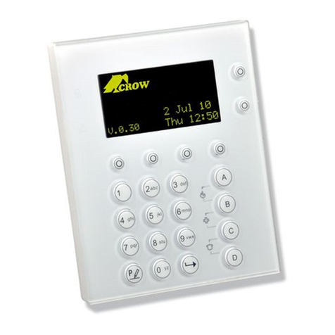
The LED Keypad shows allthe information requiredto operatethe system.The User
communicates withthe alarm system viathe keypad.The Keypad displayscontinuous
information aboutthe status of the alarm system,and enables the User to operate the systemin
different modes,change settings and programUsers' access codes.
The keypad also collects and records events to bedisplayed afterward on request,to overview
system activities,and to analyze system performance for diagnostics.
Function Keys
These keys are used to arm the system,enter commands to alter system settings,or scroll
through the history events.
=ARM, =STAY, =BYPASS, =PROGRAM, =CONTROL, =MEMORY,
=ENTER
Alphanumeric Keys
These keys are used to enter codes,Initiate Emergency or used for programming.
AudibleSignals
When the keypadis usedto activate or deactivatethe different functions it emits different
audible beeps.Theirmeaning is describedin the table below.
Table 1 Listof Audible Signals
SoundSequenceDescription
Shortbeep Once onlyA key inthekeypad has been pressed.
3 shortbeepsOnce onlyOperation carriedout successfully.
Long beep Once onlyIllegal operation or wrongkey pressed.
Slowbeeping Through the Exitor
Entry delaytime
Exitorentry delay warning. Whenarming the system,this
indicatesyoumustexittheprotected area. Whendisarmingthe
system,itindicates youhaveentered the protectedentry zone.

Keypad Description
3
Indicators
There are 30 LEDindicators to show the status of the system.
qZone and Status indicators LEDs 1- 16, =zones sealed (ready)
qPartitions indicators LEDs A or Bor C (Spare)
qMemory indicator= ,Bypass indicator=
qProgram indicator= ,Mainsindicator=
qTrouble indicator= ,Batteryindicator= ,Line indicator= ,Controlindicator=
Summary of Functions
The system's mainfunctions arelistedin table
Function Keys Description Notes
Full or
Partition ArmCC OD E CInitiatesfull arm
Full Arm CInitiatesfull arm Onlyif enabled by
installer.
Disarm
during exit CDisarms the system
during exit delay
Only whenslowbeeping
isemitted.
Disarm CC OD E CDisarms the system Stopping Alarms.
Function Keys Description Notes
Arm Stay C C C OD E CInitiatespartialalarm
when the useris home
Onlyif enabled by
installer.
Arm Stay CInitiatespartialalarm
when the useris home
DisarmStay CC OD E CDisarms the system
DisarmStay CDisarms the system
Bypass C C
Zone#
CBypasses azone(s) Repeats theprocedure to
un-bypasszones.
Initiate Panic C+ Activates emergency
alert
Onlyif enabled by
installer.
Initiate
Medical C+Activates emergency
alert
Onlyif enabled by
installer.
Initiate Fire
Alarm C+Activates emergency
alert
Onlyif enabled by
installer.
Memory CInitiatesdisplayof
events frommemory.
<ENTER> cancels
memory readout
Displays events,and
automaticallyscrollsto
the nexteventevery 2.5
sec.
(Use <MEMORY> key to
scrollup manually).
Chime
Enable/disabl
e
C C Enableor disablechime
function
Onlyif enabled by
installer
Control C C Device# CActivates ordeactivates
outputs and devices
Press<Control>for2
seconds
Change or
Add Users'
code
C C MCODE CActivates program mode
to addorchangeUsers'
codes
For details see
page 16
Note:Ifyoustarted an operation incorrectly, press toexitand returnto the previous mode.

4
Operating theKeypad
How to Arm theSystem beforeExit
Preparing the SystemforArming
Verify that allzoneindicators are off,when allzones are closed (alldoors,exits and windows are
closed and motion inthe protected area is restricted or bypassed),the systemisready to be
armed.If one or morezone indicators are illuminated,it displays theopen zones.
Closeopen zones,or bypassthem.Bypass any zone you cannot close,<Bypass> indicator
flashesindicating bypassed zone(s).For details see page 9.
Note: Bypassed zones are not protected.
Arming the System
Before leaving premises you must armthe system.
Arming the alarm system turns on all detectors in the partition/s being armed.
1. Enter your code.
2.Press < > to arm the system.
Thereis an exit delay prior to the system being armed.During this delay time,a slow
beeping is heard to indicate that the systemis not armed yet and reminds you to vacate
the protected area.
The Aor Bindicator lights up to indicate that the system is armed.
The indicators may go out few seconds after exitdelay times out,depending on theinstallation
setting.
qTo disarm the system during the exitdelay,press< >.
QuickArm(Whenenabled atinstallation)
qPress< > to arm the system.
The Aor Bindicator is lit,the systemisarmed.
During exit delaytime,a slow beeping is heard reminding you tovacate the protected area.
Disarming the System
1.Enter your code.
2.Press< >.
The Aor Bindicator goesoff,the systemis now disarmed.
Stopping and Resetting Alarms
1.Enter your code.
2.Press< >.
Thisstops the alarm at any time,and also turns off any audible sirens.

Operating theKeypad
5
ArmingtheSystem WhileStayingHome
Arming the SysteminStay Mode
Thistype of arming is used when people are present within the protectedarea.At nighttime,
when the family isabout to retire,perimeter zonesare protected,but not the interior zones.
Consequently,interior movements are ignored by the system.
1.Press < >.
2.Enter your code.
3.Press < >.
The Aor Bindicator flashes indicating that the system is now armed instay mode.
Quick Stay
This feature must be enabled atinstallation time.
qPress< > to arm the system.
During exit delayyou can leave thepremises.If you wish to stay,or you don’t want anybody
to enter the protected premises,you can cancelthe Entry/Exit delay by pressing the
< > key.
The slow beeping stops andthe system is then immediately armed.
The Aor Bindicator flashes to indicatethat thesystemisarmed instay mode.The indicators
may go out afew seconds after exit delay expired,depending on the installer's setting.
Disarming the System
Enter user’scode and press < >,or press < > if enabledby installer.
The Aor B indicatorgoes off to indicatethat thesystem is disarmed.
How to Arm Partitions
The protected area can begrouped into 3separatepartitions (Aor B).The system can be
groupedfor User‘s convenience to separate,in abusiness environment,the offices from the
warehouse area,or in aprivate residence,the different rooms of the home,e.g., living room,
bedroom,etc.
ToarmpartitionAenter usercode for partitionA
ToarmpartitionB enterusercodeforpartitionB
Note:to arming partition with code see page 8“How to arm the system before exit”
During exit delayyou can leave premises.Atthe end of the procedurethe Aor Bindicatorlights
up to indicate that the partition A or/and Bor C is armed.
(The indicators may go out after a few seconds,dependingon the installer's setting).
To disarm partition,see "Disarming the System".
How to Bypass Zones
Bypass any zone that cannot be closed.You can bypass selected zones prior to arming.Itis
also used to temporarilyexclude a faulty zone from service,which requires repair.
To bypass a selected zone,press < >,Bypass indicator lights up to indicate that the systemis
inbypassmode.
Enter the zonenumber(e.g.01, 05, 12) one or more zones,the zone LEDindicators lights up
to indicatethat thezone is bypassed,following press < >,the Bypass LED flashes to indicate
zone(s) bypassed.

Operating theKeypad
6
While in the Bypassmodeitis possibleto bypass more than one zone,press < >,the Bypass
indicator lights to indicate that the system is inbypass mode.
Add the zone number (example,03) one or morezones,the zone LEDindicatorslights to
indicate that the zoneisbypassed,then press< >,the Bypass LED flashes to indicate
zone(s) bypassed.
To resetbypassed zones,press < >,enter zonenumber (example,07, 13),the zone LED
indicators go off to indicate that the zone is no longer bypassed.Press < >.
NOTE:
Disarmingautomatically un-bypassesallzone.
UsingChime(If enabledat Installation)
A Chime(Day zone)is adetector that can be partarmed while you areat home but workingin
another part of the building.Itcan be programmed to operate a buzzeror light to let you know
you have a visitor.
To disable the Day (chime)zone,press< > and < >,ControlLEDindicatorlights up to
indicate that Chimeisdisabled.
To enableChime mode press < > and < > ControlLED goes off to indicate that Chime is
active.
Emergency Alerts
Thisthreespecial key’s function is best programmed by your installerto suit your individual
situation.Most commonly it is used ina panic situation.
These are a “PANIC”,“FIRE”,and“MEDICAL” alarm.Pressing two buttons simultaneously
generates the Panic,Fire and Medicalalarms.
How to initiate Panic
qPresssimultaneously keys < >and < >.
How to initiate Medical Alarm
qPresssimultaneously keys < > and < >.
How to initiate Fire Alarm
qPresssimultaneously keys < > and < >.
GenerateThreat or Duress
If you are compelled to disarm the system under threat,you must enter the duress digit before
the user’scode to activate the automaticdialer.The duress digit shifts up your usualcode by
one digit.If your code is 345 and 8isyour duress digit,than entering 8345 modifies your code.
The modified duress code disarms the systemin a normalway,but at the same time activates
the dialer silently to reporta “duress event” without arousing suspicion.(For detailsask the
installer).

Operating theKeypad
7
How to ReadLED Indications
LIGHT\INDICATION
ä â
OFF ON STEADY FLASHING
ZoneUnsealed
AllZones Sealed
-
Normal
Memory Display Mode
New Memory Event
BypassOff
ZoneBypassModeActive
Zone/sBypassed
RunMode
Client Program Mode
Installer Program Mode
(0)
ChimeModeON
ChimeModeOFF
-
Mains (AC)OK
-
Mains (AC)Fail
Battery OK
-
Battery Low
Normal
Trouble (Tamper)Alarm
Active
New Trouble (Tamper)
Alarm
TelephonelineisOK
Dialler is currently
making a call
The Telephone linehas
been cut or thecallwas
not
completed
ControlFunction Off
ControlMode On
ZONES 1-16
ZoneSecure
ZoneUnsealed (Not
Ready)
Zonein Alarm
ARMEDA
Partition A Disarmed
Partition A Armed
Partition A Stay Mode
ARMEDB
Partition B Disarmed
Partition B Armed
Partition B Stay Mode
ARMEDC
Spare
Spare
Spare

Operating theKeypad
8
How to ReadSystem Messages
When viewingthe memory events at the keypad by pressing the < >,the first thing that is
always displayed is the system messages.If the systemled turns ON but no other Zone LED’s
are ON at the same time,thismeans that there are no current system alarms.If a zone LED and
LED’s are ONthen thisindicates system alarms that have not yet cleared.The LED’s 1-8are pre-
defined as to what system alarm they display.These system alarmindications are shown in the
table below.
LED 1 Battery Low LED 5 RadioPendantBatteryLow
LED 2 Mains Failure LED 6 SupervisedDetector Failure
LED 3 TelephoneLine Failure LED 7 ZoneInactivity Timeout
LED 4 RadioDetector BatteryLow LED 8 DialerKiss-offFailure
Following the display of current system alarms thepanelsequences through the255 historical
memory events starting at the most recent event.The second tableshows thealarm events that
can bedisplayed in memory mode and what indicators are used to show them.
How to ReadTroubleMessages
Any failure or abnormalevents that may occur areindicated by trouble messages,and the
Trouble indicator is lit.Press< > to read out messages and other events storedin memory.
How to Display Events from Memory
The system memory stores thelast events.Press < > to displaylist of events.Following the
display of current systemalarms the panelthen sequences through the 255 historicalmemory
events starting at the most recent event.The second table shows the alarmevents that can be
displayed inmemory mode and whatindicators are used to show them.
The system displays the lastevent and automatically scrollsto the next event every 2.5seconds
whilst emitting a beep.Usethe arrowkeys to scrollup manually.
Wait untilallmessages are displayed,or press< > to cancelmemory readout.

Operating theKeypad
9
HISTORICALEVENT DISPLAYCHART
EVENTDEVICEINDICATOR STATUS
ACTIVATION Zones1-16LED's1-16 On Steady
BYPASS Zones1-
16
LED's1-16
On Steady
On Steady
DETECTOR
TAMPER
(SHORTCIRCUIT)
Zones1-8
LED's1-8
Flashing
On Steady
DETECTOR
TAMPER
(OPEN CIRCUIT)
Zones9-16
LED's9-16
Flashing
On Steady
CABINET TAMPER CabinetorSatelliteSiren Flashing
WRONGCODE
ALARM
CodeTamper at
Keypad #
LED’s1-8
Flashing
On Steady
CROWKEYPAD
TAMPERSWITCH
ACTIVATED
Keypad TamperAlarmat
Keypad #
LED’s1-8
On Steady
On Steady
LOW BATTERY Controller Battery Flashing
EVENTDEVICEINDICATOR STATUS
ACTIVATION Zones1-16LED's1-16 On Steady
BYPASS Zones1-
16
LED's1-16
On Steady
On Steady
DETECTOR
TAMPER
(SHORTCIRCUIT)
Zones1-8
LED's1-8
Flashing
On Steady
DETECTOR
TAMPER
(OPEN CIRCUIT)
Zones9-16
LED's9-16
Flashing
On Steady

Operating theKeypad
10
HISTORICALEVENT DISPLAYCHART-Continued
EVENTDEVICEINDICATOR STATUS
MAINS FAILURE Controller Mains Supply Flashing
FUSE FAILURE
(F1 orF2)
Controller on-board
Thermalfusesactivated
LED1
Flashing
On Steady
OUTPUT 1 or 2
FAIL
(Only appliesif
siren or strobe
connected)
WirestoOutput1or2
have beencut
LED’s1or2
On Steady
On Steady
On Steady
LOW BATTERY-
ZONE
(Wireless
detector)
RadioZone
Zone1-16
LED's1-16
Flashing
On Steady
LOW BATTERY-
PENDANT
(wireless
Transmitter)
RadioKey
User 21-100
Flashing
Flashing
On Steady
SENSORWATCH
TIMEOUT
Zone1-16 LED’s1-16
On Steady
Flashing
Flashing
SUPERVISED
RADIO TIMEOUT
Zone1-16 LED’s1-16
On Steady
Flashing
Flashing
RF FAILURE
No RFActivity
(0)
Flashing
Flashing
ARM
DELINQUENCY
ALARM
Area AorBnotarmed
withinprogrammed
number of days
Flashing
Flashing
DURESS ALARM
Duress Alarm
(at Keypad #)
LED’s1-8
Flashing
Flashing
On Steady

Operating theKeypad
11
HISTORICALEVENT DISPLAYCHART-Continued
EVENTDEVICEINDICATOR STATUS
KEYPADPANIC PanicAlarmatKeypad
LED’s1-8
Flashing
On Steady
PENDANT PANIC RadioPanic Alarm
LED’s9-16
Flashing
On Steady
KEYPADFIRE FireAlarmatKeypad
LED’s1-8
Flashing
Flashing
On Steady
KEYPADMEDICAL Medical Alarmat Keypad
LED’s1-8
Flashing
Flashing
On Steady
ARMED Area "A" Armed "A" On Steady
ARMED Area "B" Armed "B" On Steady
STAYMODE ON Area "A" inStayMode "A" Flashing
STAYMODE ON Area "B" inStayMode "B" Flashing
TELEPHONE LINE
FAIL
PanelDialler On Steady
EXCESSIVE RE-TRIES
PanelDialler
LED1
On Steady
On Steady
FAILURE TO GET A
KISSOFF
PanelDialler
LED2
On Steady
On Steady
WALKTESTMODE
ManualWalk-test Mode
LED’s1-16
On Steady
On Steady
On Steady
On Steady

Operating theKeypad
12
How to ControlOutputs andDevices
The keypad enables you to controlexternaldevices,such asan air-conditioner or heater.To
activate or halt a device:
1.Press <>.
The controlLEDs are constantlylit.
2.Pressthe numberof the device.
Up to eight different devices can be controlledviathe keypad.
3.Press< >.
This activates or deactivates theselecteddevice.
4.Press< >.
The LEDislit for each device ON.
5.Press< > to return to normalmode.
EnteringtheUserProgram/ClientMode
There are 2levelsof program mode, CLIENT mode and INSTALLER mode.Normally the
installer givesyou access to the CLIENT mode so you can add,delete,or change the user
codes.If you request it your installer can provide you with access to the INSTALLER mode as
well.To getintoCLIENT modeprovided the systemisNOT armed Press < > enter Master
code and < >.The Program indicator lights up to indicate that the systemisin User
programming mode.If you get a singlelong beep at this point and the Program LED doesn’t
turn on,it means your code cannot accessProgram mode.The factorydefaultmaster code(123
or 1234) isintended only as a preliminary controlcode of the alarmsystem.
Howto Exit Program Mode
If Using LEDKeypad,to exit out of programmode,press < > then < >.If Using LCD
Keypad,press < >,< > again then < >.The Program (<>indicator goes off to
indicate that the systemis no longer in User programming mode.
How to Changeor Add Codes
AboutMasterCode and the UserCode
The factory default master code (1234)isintendedas a preliminary controlof the alarm system.
After PowerWave isinstalled and putinto service,the code can be changed to any code known to
the Master user.The Master user can define upto 100 user codes.To limit access rights,the
holder of the Master codecan ask the installer to define severalUserprofiles.
Access rights are listed below:
qUser code has Area A and/or Bpermission
qUser code can arm and/ordisarm arm an area
qUser code can arm and/ordisarm arm an areain Stay mode
qUser code can change its code
qUser code can change user’s code
qUser code can Operate controlFunctions
qUser code can change dialer telephone numbers
qUser code can alter the realtime clock
qUser can answer an incoming calland start up/down load
qUser can allow access to installer program mode from client mode.
qInitiate Walk-test mode.

Operating theKeypad
13
How to Change the MasterCode
NOTE: Whenchanging theMasterCode,pleaseEnsurethatyou rememberthe new
Master Codethatyouenter.Otherwise,your systemsinstallerwillneed to comeback
toreset thecode.This may incura Service(Call Out) Fee.
While in CLIENT mode (see“Entering the user Program/Client Mode” above on page-12),Press
< > then 1 then < >,and 1then < > again,the currentMaster Code digits willbe
flashed back atyou one digitat atime.To enter a new Master code,use the numerickeyboard
to enter yournew Master code then press < >.The new Master Code willflash back at you
one digit at a time,followed either by three shortbeeps to indicatecorrect entry or onelong
beepif not accepted.The Master Code can be any combination of 1to6 digits.Itis
recommended to use at least a 4digits code but a 6digitcode will provide greater security.
To exit user Code Program mode,Press < > and < >.
How to Add orChange a UserCode (otherthanthe MasterCode)
While in CLIENT mode (see“Entering the user Program/Client Mode” above on page-12),press
< > then 1then < >,followed by the Usernumber (2to100)then < > again.If
there is an existing code already for that user,it will be flashed back at you one digit ata time.
To enter a new UserCode,use the numerickeyboard to enter your new Code then press < >.
The new User Code willflash back at you one digitat a time,followed eitherbythree short
beeps to indicatecorrect entry or onelong beepifnot accepted.A User Codecan be any
combination of 1to6 digits.Itis recommended touse atleast a 4digits code but a 6digit code
willprovide greater security.
Use the numerickeyboard to enter the new code.The code can holdany combination of 1to6
digits.Entering the new code deletes the old code. Press < > to save your new code,the new
code is flashed back toyou together with three short beeps.
Repeat the procedure for allusers.
To exit user Code Program mode,Press < > and < >.
How to Delete the UserCode (Itis Advisable to Change acode andNot deleteit)
While in CLIENT mode (see“Entering the user Program/Client Mode” above on page-12),press
< > then 1then < >,followed by the Usernumber (2to100)you intend todelete then
press < > again.If thereis anexisting code already for that user,itwillbe flashed back at
you one digitat atime.Press < > to delete User code.
Press< > to save the change.
To exit user Code Program mode,Press < > and < >.
Adding/ChangingTelephoneNumbers
Your panelaccepts up to six phone numbers with a totalof 16 digits.Your panel can be
programmed to dialallor any of these depending on the event which hasoccurred. (The eight
phone numbers are at program address P181E 1-8E).
While in CLIENT mode,key in thefollowing sequence < > 181 < > 1 < >
(The address for telephone number 1),the existing number is flashed out at the keypad then
enter <NEW TELEPHONE #>< > The new numbers are flashed backto confirm
acceptance.
At any time you can enter in theaddress for the telephone number just to viewthe currently
programmed value then press the < > button to move on tothe next address.
Forexample,P181E 1E=PH # 1, P181E 2E=PH# 2, P181E 6E= PH# 6.
NOTE:
On the LEDkeypad“0” isindicatedbyLED“A” and“9” by LED“B”.

Operating theKeypad
14
How to set TimeandDate
The alarm system has an internal clock that maybe used to automaticallyArm or Disarm the
alarm or turn Outputs On or off.Itis alsoused to identifywhen events occurred inmemory via
the LCD keypad.If you need to change the Time &Dateitmust bedone from the CLIENT
mode.To change the Time & Date press
Press < > <26>< ><2>< ><1-7> < >
Where 1-7= the current day (1=Sun,2=Mon to 7= Sat)
Press < > <26>< ><1> < ><HHMM>< >
Where HH = Hour in 24 Hour Format and MM =Minutes
Press < > <26>< ><3>< ><DDMMYY> < >
Where DD=1-31 current date,MM= months 1-12, YY =year 00-99
How to OperatetheAccess ControlOutput
If the alarm system has been set up to allow controlof an electric doorlock,you can activatethe
door release function as follows;
Press< > or Press< > enter CODE then < >.The ControlLED is lit while thelockis
active,and turns off as soon as power isremoved from thelock.
The Access Controlfunction can either be a single button operation or restricted to requiring a
validUsercode entry.Both options are shown above.Pleaseconsult your installeras to what
option may be programmed.
How to start Walk Test Mode
While in CLIENT mode aUserwith the proper authority can startwalk-test mode.This special
mode latches the alarmsignals from detectors atthe keypad initiating the testso that one
person can trigger every detector connected to thealarm then return to the keypad to verify
operation.OnterminatingWalk-test mode the testresults are putinto the memory buffer so
they can beviewedat alater time.
To start Walk-test mode while in CLIENT mode press < > <200> < ><6> < > and
the keypad buzzer beeps at 1-second intervals.
Next trigger every detector connected to the panel then return to the keypad and allof the zones
that were triggered are displayed on the keypad.
To terminate Walk-test mode press <>,the keypad stops beeping and automatically exits
CLIENT mode.
How to Answer an In-ComingCall
From time to timeyour installer may need to access the alarm from a remote PC to make
changes to your programmingand for security reasons they may have configured thealarm so
that an authorized person on-siteisrequired to make the alarm system answer thein-coming
call.This option is only available in CLIENT mode.
If the panelis not configured to answerin-coming calls,the user can force itto answer the call
by pressing and holding < > followed within 2seconds by <9>.This forces the panelto
answer the call immediately.For thisfunctionto work the phone line must be ringing at the time
and there must have been at least two rings before pressing thebuttons.
Provided the line connected tothe alarm was ringing at the time,the panelnow answers the call
and allows a remote PC connection.

Operating theKeypad
15
UsingtheRemoteCommandControl
Another powerful feature available from your alarmisCommand Control.This featureisa
remote controlfacilitywhich allows valid users to access the panelvia a standardtouch tone
telephone and checkor changes the Arm/Disarm status of each of the areas,operate each of the
eight outputs or turn on an optionalMicrophone.
The Command Controlfeatureis only available on panelsfitted with a Voice or DTMF board.The
Voice board provides voice prompts to guide youthrough Command controloperations whereas
the DTMF board provides tones (one Long ToneforON or three short beeps for OFF).
Please talk to your installer to findout if all or anyof these options are available onyour alarm.
To perform any of the Command Controlfeatures you must first ring the phone number,which
the panelis connected to.The panelmay be set up to answer after a specific number of rings or
it can be set-up to use a fax defeat option.Either way,when you ring the phone number and
the panelanswers the call,thefirst thing you hearover the phoneisa two seconds burst of
modem tone.After thistone stops you must enter the access code,which is associated with the
Command menu option you wish to access.Remember,the code you enter determines which
menu option you access.If you miss the pause,the panel repeats the modem tone and then
pauses again for 5secondslooking for your accesscode.Thisprocess is repeated four times
before hanging up,if no validcode is received.When entering codes or other information in
Command Controlthe "#" key acts as a "Clear"button.
When you have entered the required 4-digitaccess code the panelreplies with the status
message associated with the Command Controlfunction you have accessed.For example,let's
say we have a code of “2045” to allow Arming &Disarming of Area A.Once the code “2045” has
been received the panelchecks the current status of Area A and replies with the pre-
programmed voicemessage relating to that status.For example,if AreaA is armed,then the
Armed message is sent,if Disarmed thenthe Disarmed message is sent.If only the DTMF board
is fitted,the voicemessage is substituted with along beep if Area A is armed and three short
beeps ifit isdisarmed.
Once thestatus message hasinformed you of the actualstate,you can use the "*" key to toggle
the option on & off orArm and Disarm,e.g.inour example above,code “2045” accesses Area
"A" arming or disarming.
Assuming thestatus message we received was"Area A alarm is Armed" If we press the "*" key,
Area "A" isDisarmed and wewould receive astatus message "Area A alarm isDisarmed" (or
whatever message is programmed by the installer).
While you are on-line with the panelyou can move between menu options by entering the code
of the option youwant to control.Assuming therewas a code of “4321” programmed tocontrol
outputs.After having used code “2045” to controlthe Arm/Disarm status of Area A we first press
the “#” button to reset allprevious entries.Then we can enter the digits “43215” (that is“4321”
as thecode to controloutputs and “5” to select output #5).The current status of output#5is
giveneither by thevoicemessage or the appropriate tone and then the status can be changed
with the “*” button on the remote telephone.
NOTE:
For output control you must enter the 4 digit code,for example,4321 followedby the
output numberyou wish to control, in thiscase5.
At any stage,ifyou enter in an incorrect code you can press the “#” button on the remote
telephone to clear all code entries and then start again.
To turn on the optionalMicrophone (only available ifthe Voice Boardis fitted) you must enterin
the appropriate code followed by the “*” button.To turn the Microphone off you simplypress the
“*” button again.
To end a Command Controlsessionsimply hangs up the phone.The panelis monitoring the line
at alltimes and 15 secondsafter thelast key pressit automatically hangs up the line.This 15-
secondtimer is active during the whole command controlprocess soa period of 15 seconds
withouta keypress causes the panelto hang-up.

Operating theKeypad
16
UsingLocalCommandControl
If a command controlcode for outputsisprogrammed and the output/s are allowed to be locally
controlled from thekeypad,then entering the 4digit code at a keypad blanksthe display and the
zone LED’s now indicate theoutput status.Forexample,if output1is on zone 1LED is on.
Pressing the “1” button at the panelkeypad,output 1can be turned off provideditis allowed to
be locallycontrolled.To leavelocal commandcontrolmodesimply press the < > button and
the keypad returns to normaloperation.This feature works the same way that “Directly
Controlling an Output” works only it requires a code to access the function.
Other manuals for Runner Series
4
Table of contents
Other Crow Keypad manuals
