TATRAMAT EO 30 EL Instruction Manual

TATRAMAT - ohrievače vody, s.r.o.
EO 30 EL
EO 50 EL
EO 80 EL
EO 100 EL
EO 120 EL
EO 150 EL
GB Wall mounted water heater with PCB
Operation and installation 7
CZ
SK

A
1
2
3
26_02_07_0278
B
1
2
3
1
2
3
26_02_07_0284
C
E-NO.: 000000
F-NO.: 0000-000000
26_02_07_0301
D
1
2
3
26_02_07_0300

E
26_02_07_0296
F
26_02_07_0296

G
1
26_02_07_0287
H
b01
i13
100
a20
a30
a10
c01
c06
h46
c01
c06
D0000018833

I
30 - 50 l
184
265
300
360
80_02_07_0005
80 - 150 l
450
415
360
350
300
265
80_02_07_0006

J
FB
L1
CB
L3
N
L2
L1
L3
N
L2
PE
5
6
LF
X6
ws
vi
S
E Z B
X2X12
X10
X7
A
E
A
E
X2 X1
5
5
3
3
X9
R
3
R
1
12 13
2
5
67
910 11
4
8
85_02_07_0022
K
L1L3 NL2 PE56
1
85_02_07_0020
L
1
L1
L3 N
L2 PE
5
6
85_02_07_0021
M
L1
L3 N
L2 PE
5
6
85_02_07_0018
N
L1
L3 N
L2 PE
5
6
85_02_07_0019
O
L1
L3 N
L2 PE
5
6
85_02_07_0024

7
GB
Contents
OPERATION
1 GENERAL INFORMATION _____________________________________________________________________ 8
1.1 Safety instructions _____________________________________________________________________________ 8
1.2 Other symbols in this documentation _____________________________________________________________ 8
1.3 Units of measurement __________________________________________________________________________ 9
2 SAFETY______________________________________________________________________________________ 9
2.1 Intended use __________________________________________________________________________________ 9
2.2 Safety instructions _____________________________________________________________________________ 9
2.3 CE designation ________________________________________________________________________________ 9
2.4 Test symbols__________________________________________________________________________________ 9
3 APPLIANCE DESCRIPTION____________________________________________________________________ 9
4 SETTINGS __________________________________________________________________________________ 10
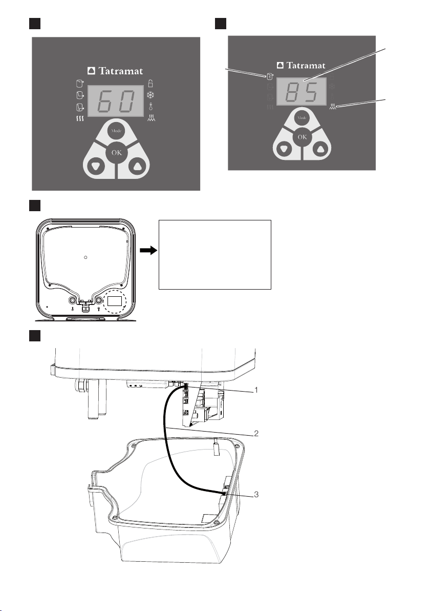
4.1 Controls, display and symbols__________________________________________________________________ 10
4.2 Factory settings ______________________________________________________________________________ 10
4.3 Set temperature and frost protection settings_____________________________________________________ 11
4.4 Menu functions_______________________________________________________________________________ 11
4.5 Enabling/disabling key lock ____________________________________________________________________ 14
5 CLEANING, CARE AND MAINTENANCE _______________________________________________________ 15
6 TROUBLESHOOTING ________________________________________________________________________ 15
INSTALLATION
7 SAFETY_____________________________________________________________________________________ 16
7.1 General safety instructions_____________________________________________________________________ 16
7.2 Instructions, standards and regulations __________________________________________________________ 16
8 APPLIANCE DESCRIPTION___________________________________________________________________ 16
8.1 Standard delivery _____________________________________________________________________________ 16
9 PREPARATIONS_____________________________________________________________________________ 16
9.1 Installation site _______________________________________________________________________________ 16
10 PREPARING FOR INSTALLATION _____________________________________________________________ 16
10.1 Preparing to install the appliance________________________________________________________________ 16
10.2 Water connection_____________________________________________________________________________ 16
10.3 Electrical connection __________________________________________________________________________ 17
11 COMMISSIONING ___________________________________________________________________________ 18
11.1 Commissioning_______________________________________________________________________________ 18
11.2 Returning into use ____________________________________________________________________________ 18
12 SETTINGS __________________________________________________________________________________ 18
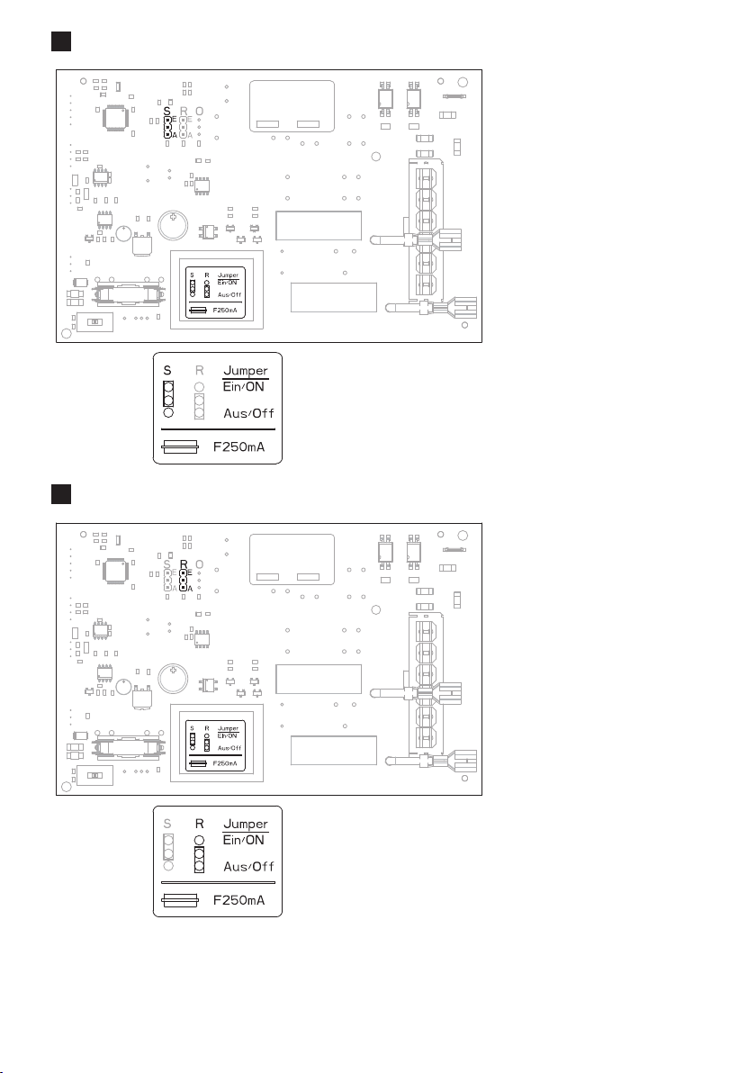
12.1 Switching on commercial mode ________________________________________________________________ 18
12.2 Switching on reverse control ___________________________________________________________________ 19
13 TAKING THE APPLIANCE OUT OF USE________________________________________________________ 19
14 MAINTENANCE _____________________________________________________________________________ 19
14.1 Checking the safety assembly and safety valve ___________________________________________________ 19
14.2 Draining the appliance_________________________________________________________________________ 19
14.3 Checking the protective anode _________________________________________________________________ 19
14.4 Descaling____________________________________________________________________________________ 20
14.5 Installing the temperature limiter ________________________________________________________________ 20
15 TROUBLESHOOTING ________________________________________________________________________ 20
16 SPECIFICATION _____________________________________________________________________________ 21
16.1 Dimensions and connections___________________________________________________________________ 21
16.2 Wiring diagrams and connections_______________________________________________________________ 21
16.3 Fault conditions ______________________________________________________________________________ 22
16.4 Data table ___________________________________________________________________________________ 23
WARRANTY
ENVIRONMENT AND RECYCLING

8
OPERATION GB
1 GENERAL INFORMATION
The chapter "Operation" is intended for appliance users and heating contractors.
The chapter "Installation" is intended for heating contractors.
Note
Read these instructions carefully before using the appliance and retain them for future
reference.
Pass on the instructions to a new user if required.
1.1 Safety instructions
1.1.1 Structure of safety information
KEYWORD Type of risk
Here, possible consequences are listed that may result from failure to observe the
safety instructions.
»Steps to prevent the risk are listed.
1.1.2 Symbols, type of risk
Symbol Type of risk
!
Injury
Electrocution
Burns or scalding
1.1.3 Keywords
KEYWORD Meaning
DANGER Failure to observe this information
will result in serious injury or death.
WARNING Failure to observe this information
may result in serious injury or death.
CAUTION Failure to observe this information
may result in non-serious or minor
injury.
1.2 Other symbols in this documentation
Note
»Read these notes carefully.
Symbol
!
Damage to the appliance and environment
Appliance disposal
»This symbol indicates that you have to do something. The action you need to take is described step
by step.
A
This symbol is a reference to Fig. A at the start of the document.
OPERATION

9
OPERATION GB
1.3 Units of measurement
Note
All measurements are given in mm unless stated otherwise.
SAFETY
2.1 Intended use
The appliance is intended for heating domestic hot water and can supply one or more draw-off points.
This appliance is designed for domestic use. It can be used safely by untrained persons. The appliance can
also be used in a non-domestic environment, e.g. in a small business, as long as it is used in the same way.
Any other use beyond that described shall be deemed inappropriate. It is not permissible to heat other
liquids or materials. Observation of these instructions and of instructions for any accessories used is also
part of the correct use of this appliance.
2.2 Safety instructions
DANGER Scalding
!WARNING Injury
The appliance may be used by children aged 8 and up and persons with reduced physical,
sensory or mental capabilities or a lack of experience provided that they are supervised
or they have been instructed on how to use the appliance safely and have understood the
resulting risks. Children must never play with the appliance. Children must never clean
the appliance or perform user maintenance unless they are supervised.
!Damage to the appliance and environment
Protect the water lines and the safety assembly against frost.
Note
The appliance is under pressure. During the heat-up process, expansion water will drip
from the safety valve. If water continues to drip when the heat-up process is completed,
and if the water pressure is lower than 0.6 MPa, please inform your heating contractor.
2.3 CE designation
The CE designation shows that the appliance meets all essential requirements according to the:
-Electromagnetic Compatibility Directive
-Low Voltage Directive
2.4 Test symbols
See type plate on the appliance.
3 APPLIANCE DESCRIPTION
The appliance electrically heats up domestic hot water with the standard heating output or with rapid
heating. The electronic control unit makes energy saving adjustments easier. Subject to the power supply
and draw-off behaviour, the water is heated automatically to the set temperature.
The digital display provides you with information about the selected set temperature and the enabled
functions.
The current temperature standard value is provided by the analogue temperature indicator.
The inner cylinder is protected against corrosion by an enamel coating in conjunction with the integral
protective magnesium anode.

10
OPERATION GB
The expansion water that collects as the water is heated up is drained off via the safety valve.
The thermal insulation is made of environmentally friendly and recyclable polyurethane foam.
The water heater is protected against frost, but the safety valve and water lines in the apartment or house
are not. If the appliance is disconnected from the power supply, the water heater is not protected against
frost. In such cases, if there is a risk of frost, the water heater must be drained.
The appliance can be operated in three ways: as a single circuit, dual circuit or manually.
Single circuit operation
In this operating mode, the appliance heats up the water automatically with the standard heating output
at any temperature setting. You can also start rapid heating.
Dual circuit operation
During off-peak tariff periods (cheap rate periods of power supply utilities), the appliance automatically
heats up the water heater content with the standard heating output at any temperature setting. You can
also start rapid heating.
Manual operation
The appliance only heats the water when the rapid heating button is pressed. Once the maximum possible
temperature has been reached, the appliance switches off and does not restart automatically.
SETTINGS
4.1 Controls, display and symbols
A
The set temperature is displayed.
Button Description Symbol Description Symbol Description
Mode
Selection of the menu function
1
saving mode Key lock
OK
Confirmation of the displayed value
2
-
ing mode Frost protection
Minus
Reduction of the displayed value
3
saving mode Temperature limit
Plus
Increase of the displayed value Rapid heating Heat-up
During operation, the symbols for all enabled functions are illuminated.
When setting the menu functions, only the symbol for the current function and, if required, the heat-up
symbol are displayed. The current setting of the function is displayed.
As soon as you press a button, the display and symbols are illuminated again.
4.2 Factory settings
Symbols indicate that the
appliance has heated up the water and ECO Comfort energy saving mode is selected.
B
1
2 Heat-up symbol
3 ECO Comfort energy saving mode symbol (factory setting)

11
OPERATION GB
4.3 Set temperature and frost protection settings
The current set temperature is displayed. Factory setting:
»Use the plus and minus buttons to adjust the set temperature from 20 to
As soon as the water temperature drops below the selected value, the heating
element automatically switches on. The heat-up symbol is displayed until the
temperature reaches the selected set temperature again.
7
frost protection symbol appears.
Note
energy saving mode.
For low water consumption or very hard water, we recommend a low set temperature, as water above
4.3.1 Holiday and absence
»
disconnect the appliance from the power supply in order to save energy.
»
use.
4.4 Menu functions
4.4.1 General menu settings principle
Note
Your settings are retained even after disconnection from the power supply.
When carrying out menu settings, if you do not make any entry for 15 seconds, the set
temperature is displayed again. You setting is not saved.
»Call up all menu functions one after the other using the mode button.
The symbol for the current menu function appears. The heat-up symbol may
light up, but no other symbols are illuminated.
The current setting is displayed:
0Function off
1Function on
40-60
To change the setting, proceed as follows for all menu functions:
»Switch on the menu function using the plus button or adjust the value.
»Switch off the menu function using the minus button or adjust the value.
»
The current setting for the menu function is saved. The set temperature is dis-
played.

12
OPERATION GB
4.4.2 Displaying the fault code
E... »Press the mode button.
-
shooting") is displayed.
4.4.3 Selecting energy saving mode
ECO Comfort (factory setting)
This energy saving mode always offers you the maximum amount of hot water and therefore maximum
comfort.
This is also possible immediately after commissioning and after automatic reduction of
the set temperature.
ECO Plus (with single circuit operation)
This energy saving mode offers you the advantage of energy savings, as heating is only carried out after
considerable draw-off.
drawn off 40% of the water heater content.
ECO Dynamic (with single circuit operation)
your draw-off behaviour.
When you select ECO Dynamic mode, the appliance evaluates your draw-off times and quantities for a
week. The next week, you have the required mixed water volume available at the draw-off time. The ap-
pliance monitors your user behaviour and automatically adjusts the heat-up times as required.
This energy saving mode is optimal if you require hot water at the same time during a week. If your draw-
off times change, hot water is available the next week at the new times.
Note
In commercial mode (see chapter "Commercial mode") and in manual operating mode
(see chapter "Appliance description"), the ECO menu functions are skipped.
1
1»
Note
is switched on or reverse control is enabled in dual circuit operation. These menu func-
tions are then skipped.

13
OPERATION GB
2
0»
30»
Note
»Switch the menu function on using the plus button or off using the minus button and
4.4.4 Commercial mode
The heating contractor can adjust the appliance for commercial applications, e.g. in doctors’ practices or
butchers (see chapter "Installation/settings"). The set temperature is then adjusted manually. The energy
saving mode button is not enabled in commercial mode.
4.4.5 Adjusted use of off-peak tariff periods
(reverse control with dual circuit operation)
This function is not enabled in the factory settings. The heating contractor can enable reverse control of
the appliance.
This means that the appliance evaluates the cheap rate periods of your power supply utility for 7 days to
make the most of off-peak times. The aim is to start heat-up at the right time so that the full water heater
content heated to the set temperature is only available to you at the end of the off-peak time (optimum
standby energy consumption).
4.4.6 Switching rapid heating on/off
With rapid heating, the appliance heats the water content up to maximum temperature. If you have switched
on a temperature limit, the selected temperature limit is also the maximum value for the set temperature.
Once the maximum temperature has been reached, the rapid heating function is switched off automati-
cally. In standard mode, the previously selected set temperature is enabled again.
0»Keep pressing the mode button until the rapid heating symbol appears.
Note
»Switch the menu function on using the plus button or off using the minus button and

14
OPERATION GB
4.5 Enabling/disabling key lock
Starting
0»Keep pressing the mode button until the key lock symbol appears.
1»Enable key lock using the plus button.
Note
»
Stopping
3 s
0»To disable key lock, press the plus and minus buttons simultaneously for 3
seconds.
disabled.
4.5.1 Switching frost protection on/off
0»Keep pressing the mode button until the frost protection symbol appears.
Note
»Switch the menu function on using the plus button or off using the minus button and
4.5.2 Setting the temperature limit
Note
Starting and setting
0»Keep pressing the mode button until the key lock symbol appears.
»
and minus buttons.
Note
»

15
OPERATION GB
Stopping
1»Keep pressing the mode button until the temperature limit appears.
0»Switch the temperature limit off by selecting the setting 0with the minus
button.
Note
»
CLEANING, CARE AND MAINTENANCE
»Never use abrasive or corrosive cleaning agents.
appliance.
»Check the taps regularly. You can remove limescale deposits at the tap outlets using commercially
available descaling agents.
»Have the electrical safety of the appliance and the function of the safety assembly regularly checked
by a heating contractor.
» The
heating contractor will then determine the intervals at which it must be checked thereafter.
»Regularly activate the safety valve to prevent it from becoming blocked by limescale deposits.
6 TROUBLESHOOTING
Problem Cause »Remedy
The water does not heat up and the
display does not light up. There is no power. Check the fuse/MCB in your fuse
box/distribution panel.
The water does not heat up sufficient-
ly and the heat-up symbol lights up. The set temperature is set too low. Select a higher set temperature.
The appliance heats, for example,
after large amounts of DHW have been
drawn.
Wait until the heat-up symbol goes out
again.
The outlet flow rate is low. The aerator in the tap or shower head
is scaled up or contaminated. Clean and/or descale the aerator or
shower head.
The appliance does not respond
when a button is pressed.
The key lock symbol is flashing.
Key lock is enabled. Disable key lock (see chapter "Set-
tings / Menu functions / Enabling/
disabling key lock").
The display flashes. Notify your local contractor. Display
the fault code (see chapter "Settings /
Menu functions / Displaying the fault
code").
If you cannot remedy the fault, notify your heating contractor. To facilitate and speed up your enquiry,
please provide the serial number from the type plate (000000 and 0000-000000):
C

16
GB
INSTALLATION
7 SAFETY
appliance.
7.1 General safety instructions
We guarantee trouble-free operation and operational reliability only if the original accessories and spare
parts intended for the appliance are used.
7.2 Instructions, standards and regulations
Note
Observe all applicable national and regional regulations and instructions.
8 APPLIANCE DESCRIPTION
8.1 Standard delivery
Delivered with the appliance:
-Fitted wall mounting bracket
-Safety valve (SYR) with non-return valve
9 PREPARATIONS
9.1 Installation site
The appliance is designed for installation on a solid wall. Ensure the wall offers adequate load bearing
capacity.
There should be a suitable drain near the appliance to drain off the expansion water.
»Install the appliance vertically in a room free from the risk of frost and near the draw-off point.
10 PREPARING FOR INSTALLATION
10.1 Preparing to install the appliance
The mounting bracket attached to the appliance has hook-in slots, which in most cases enables instal-
lation on the bolts that are already in place from previous appliances.
»
/ Dimensions and connections").
»Drill the holes, if required, and secure the wall mounting bracket with screws and rawl plugs. Select
»Hook the appliance with the wall mounting bracket on to the screws or bolts. Observe the weight of
person to help.
»Align the appliance vertically.
10.2 Water connection
!Damage to the appliance and environment
Make all water connection and installation work in accordance with regulations.
Cold water line
Steel or copper pipes or plastic pipework are approved materials.
DHW line
Copper or plastic pipework are approved materials.
INSTALLATION

17
GB
INSTALLATION
!Damage to the appliance and environment
Note
inlet".
Operate the appliance only with pressure-tested taps.
»
gets into the water heater or safety valve.
»Route the safety valve drain line to a drain free from the risk of frost, with a continuous downward
The discharge aperture of the safety
valve must remain open to the atmosphere.
10.3 Electrical connection
DANGER Electrocution
Before any work on the appliance, disconnect all poles of the appliance from the power
supply.
DANGER Electrocution
Carry out all electrical connection and installation work in accordance with relevant regu-
lations.
DANGER Electrocution
Only use a permanent connection to the power supply. The appliance must be able to be
separated from the power supply by an isolator that disconnects all poles with at least
Note
Observe the type plate.
Note
Please note that the appliance must be connected to the earth conductor.
D
1 Electronic assembly, control unit, position X2
2 Connecting cable, electronic assemblies
3 Electronic assembly, operation
Removing the lower cover
»Undo the 4 screws.
»Remove the bottom cap.
»Disconnect the connecting cable from the electronic assembly for operation, position X2.
Also in dual circuit operation:
»Pull out the cable grommet at the base while pressing the snap-in tabs.
»Push the cable grommet over the power cable and snap the cable grommet back in place.

18
GB
INSTALLATION
Selecting the operating mode
!Damage to the appliance and environment
Only change the operating mode when isolated from the power supply.
E Single circuit operation
Z Dual circuit operation
B Manual operation
»Select the operating mode with the switch on the control unit electronic assembly and select the
»
Wiring diagrams and connections").
»Secure the bottom cap with the 4 screws.
Power cable
DANGER Electrocution
The power cable must only be replaced (for example if damaged) by contractors author-
ised by the manufacturer.
» Use a suitable installation cable.
»When routing the new power cable, ensure that it is waterproof as it passes through the existing
cable grommet, and is correctly routed and connected inside the appliance.
11 COMMISSIONING
11.1 Commissioning
»Open the shut-off valve in the cold water line.
»
»
Data table").
»Switch the mains power ON. The appliance carries out a self-test.
»Check the function of the appliance.
»Check the function of the safety valve.
11.1.1 Appliance handover
»Explain the appliance function to users and familiarise them with its operation.
»
»Make the user aware of potential dangers, especially the risk of scalding.
»Hand over these instructions.
11.2 Returning into use
See chapter "Commissioning".
SETTINGS
12.1 Switching on commercial mode
E
S Jumper ECO (energy saving mode)
E ECO ON (factory setting)
A ECO OFF (commercial mode)
»To switch on commercial mode, replug the jumper.

19
GB
INSTALLATION
12.2 Switching on reverse control
F
R Reverse control jumper
E Reverse control ON
A Reverse control OFF (factory setting)
»To switch on reverse control, replug the jumper.
13 TAKING THE APPLIANCE OUT OF USE
»Disconnect the appliance from the mains at the MCB/fuse in the fuse box.
»Drain the appliance. See chapter "Maintenance / Draining the appliance".
MAINTENANCE
DANGER Electrocution
Before any work on the appliance, disconnect all poles of the appliance from the power
supply.
DANGER Electrocution
Carry out all electrical connection and installation work in accordance with relevant regu-
lations.
If you additionally need to drain the appliance, observe chapter "Draining the appliance".
14.1 Checking the safety assembly and safety valve
»Check the safety assembly and safety valve regularly.
14.2 Draining the appliance
DANGER Scalding
Hot water may escape during the draining process.
If the appliance needs to be drained for maintenance or to protect the whole installation when there is a
risk of frost, proceed as follows:
»Close the shut-off valve in the cold water line.
»Drain the appliance by opening the shut-off valve at the safety valve.
14.3 Checking the protective anode
»
»Afterwards determine the time intervals at which further checks should be carried out.

20
GB
INSTALLATION
14.4 Descaling
»Remove loose scale deposits from the water heater.
»If necessary, descale the inner cylinder with commercially available descaling agents.
»
with descaling agents.
14.5 Installing the temperature limiter
26_02_07_0305
1
1 Limiter sensor
»Insert the limiter sensor into the sensor well as far as it will go.
TROUBLESHOOTING
Note
The appliance
may be subjected to these temperatures during storage or transport.
»Display the fault code (see chapter "Settings / Menu functions / Displaying the fault code").
»
Fault Code Cause »Remedy
The heat-up time is very long
and the heat-up symbol lights
up.
The flanged immersion heater is
scaled up. Descale the flanged immersion heater.
The safety valve is dripping and
the heat-up symbol does not
light up.
The valve seat is contaminated. Clean the valve seat.
The display flashes. E2 The temperature sensor is faulty. Check whether plug X10 is properly
inserted.
E4 Check the temperature sensor.
E1
28
Communication between the elec-
tronic assemblies for control unit
and operation is faulty.
Check whether plugs X2 are inserted
properly in both assemblies.
Check the assemblies and the con-
necting cable.
The water does not heat up.
The heat-up symbol does not
appear.
The display flashes.
E8 The high limit safety cut-out has
responded. Check the appliance and eliminate the
cause.
Press the reset button (see diagram).
The high limit safety cut-out has
responded because the thermostat
is faulty.
Remedy the cause of the fault. Replace
the high limit safety cut-out.
The high limit safety cut-out has re-
sponded because the temperature
Press the reset button (see diagram).
The flanged immersion heater is
faulty. Replace the flanged immersion heater.
The water does not heat up.
The display flashes. E6 The temperature sensor is faulty. Check whether plug X10 is properly in-
serted. Check the temperature sensor.
This manual suits for next models
5
Table of contents
Languages:
Other TATRAMAT Water Heater manuals
Popular Water Heater manuals by other brands

Webasto
Webasto Thermo Top E installation instructions

Dimplex
Dimplex DHWE 50S Installation and operating instructions

Chromalox
Chromalox NWH-185015 Installation, operation and renewal parts identification

Webasto
Webasto Thermo Top C-B installation instructions

Rheem
Rheem RTG-3 Series use and care manual

Thermann
Thermann 26NG50C Installer manual