Tavistock Kinetic SKN0601 Parts list manual

KINETIC & LOGIC
THERMOSTATIC SHOWER BAR VALVE
Installation & aftercare instructions
Please retain for future reference
KINETIC BAR SHOWER VALVE
SKN0601
KINETIC BAR SHOWER VALVE
SKN0706
TMV2 / Buildcert Ref No: RRTAV6 TMV2 / Buildcert Ref No: RRTAV7
REF: KH.TAV.BSV10 | 07.10 V3.00
LOGIC BAR SHOWER VALVE
SLG1302
LOGIC BAR SHOWER VALVE
SLG1407
TMV2 / Buildcert Ref No: RRTAV13 TMV2 / Buildcert Ref No: RRTAV14

INTRODUCTION
Your bar shower valve is a thermostatic mixer which incorporates a thermo-regulating cartridge to assure users
of consistent showering temperatures. The valve has been designed & manufactured to comply with BS EN
1287:1999 & BS EN 1111:1999.
OPERATING CONDITIONS OF USE
Before installation the operating conditions of use must be checked. The table below contains details of the
necessary conditions of operation. If your water supply cannot meet these conditions then the valve cannot be
guaranteed to operate as a Type 2 TMV2 certified shower valve. This valve is suitable for use in both low
pressure (BS 1287) and high pressure (BS 1111) operating conditions with the following systems:
• Gravity fed Hot & Cold (equal pressures)
• Gravity fed Hot & mains Cold (differential pressure – max ratio 3:1)
• Unvented systems
• Gas combination boiler
• Pumped system
Note: On gravity systems the minimum Vertical distance (Drop) from the underside of the cold water storage
tank to the shower valve must be 3 metres.
CONDITIONS OF USE FORTYPE 2 VALVES
NOTE:
Valves operating outside these conditions cannot be guaranteed by the Scheme to operate as Type 2 valves.
Recommended outlet temperatures
The BuildCert TMV scheme recommends the following set maximum mixed water outlet temperatures for use
in all premises:
41°C for showers;
The mixed water temperatures must never exceed 46°C.
The maximum mixed water temperature can be 2°C above the recommended maximum set outlet
temperatures.
NOTE:
46°C is the maximum mixed water temperature from the bath tap. The maximum temperature takes account
of the allowable temperature tolerances inherent in thermostatic mixing valves and temperature losses in metal
baths.
It is not a safe bathing temperature for adults or children.
The British Burns Association recommends 37 to 37.5°C as a comfortable bathing temperature for children. In
premises covered by the Care Standards Act 2000, the maximum mixed water outlet temperature is 43°C.
The thermostatic mixing valve will be installed in such a position that maintenance of the TMV and its valves
and the commissioning and testing of the TMV can be undertaken.
The fitting of strainers is recommended as close as is practicable to the water supply inlets of the thermostatic
mixing valve.
SERVICE INTERVALS
Subsequent frequency can be determined with reference to previous test results. Where no significant deviation
was recorded the test interval can be made equal to the maximum recorded interval to that point.
Note. Check valve and strainer servicing must be conducted at each test interval.
If the recorded mixed water temperature is greater than > 2°K from the initial recorded settings or the set point
cannot be reached / stabilised further action is required.
It is important to establish that the incoming water supplies still satisfy the initial guidance and also that no
additional draw off variation that could affect performance has occurred.
The material selection for this valve has excellent resistance to scale build up and is designed such that there
are no serviceable parts beyond items 1 & 2 as described previously.
In the very unlikely event that initial performance cannot be achieved, and all external parameters are correct,
the unit may require replacement.
10-YEAR GUARANTEE
HIGH PRESSURE LOW PRESSURE
Maximum Static Pressure - BAR
Flow Pressure, Hot & Cold - BAR
Hot SupplyTemperature - °C
Cold SupplyTemperature - °C
10
0.5 to 5
55 to 65
Equal to or less than 25°C
10
0.1 to 1
55 to 65
Equal to or less than 25°C
We have complete confidence in this Tavistock product and as such it is offered with a 10-year guarantee
against defects in manufacture. This valve must be fitted by a competent installer. If in doubt seek advice from
a qualified professional.
The guarantee requires that this product be used in the manner for which it was intended and that it is installed
& maintained in accordance with the fitting instructions and local water bylaws. The guarantee covers products
in domestic use only.
Always ensure this product is fully tested before concealing valves into the wall. On installation ensure that the
valve and valve inlet threads can be removed or serviced in accordance with TMV2 regulations. The guarantee
is invalidated should the valve be damaged by water borne debris. Make sure that supply pipes are clear of
any debris prior to installation, this is particularly important on new plumbing installations. In the unlikely event
that this product should fail during the guarantee period we will either replace the faulty part or the complete
unit as appropriate.
This guarantee excludes normal wear and tear. This guarantee covers failure of the thermostatic cartridge
within the first 2 years of purchase only. Replacement cartridges are available to purchase by contacting the
Tavistock Customer Service team. Failure to follow the terms outlined above will invalidate this guarantee.
Proof of purchase will be required to validate any guarantee claims.
VALVE INSTALLATION GUIDELINES AND COMPLIANCE
The valve must be installed so that it is readily accessible for commissioning and maintenance in accordance
with the TMV2 scheme. The valve must be installed with isolation valves on both the hot and cold water
systems as close as possible to the valve; so as to allow the valve to be commissioned and tested correctly.
The valve is fitted with integral check valve cartridges which command the water supply, therefore the
thermostatic valve is protected against cross-flow due to unbalanced line pressures as required by the Water
Supply (Water Fittings) Regulations 1999.
Most problems associated with the operation of thermostatic shower valves are caused by debris in the new
pipe work getting into the thermostat. These problems are easily avoided by thoroughly flushing the pipe work
BEFORE the shower valve is fitted.
WATER SUPPLY - (WATER FITTINGS) REGULATIONS 1999
This valve complies with the requirements of the above regulations and installation should be carried out in
strict compliance with them.
MOUNTING BAR SHOWER VALVES
There are two methods of mounting the bar shower valve using the components supplied. These methods are
detailed on the following pages. Please read the information below to determine the most suitable option for
your installation:
Option 1 - Cranked connector
This option requires a 1/2” BSP female adapter (not supplied) to connect the cranked connectors to the pipe
work. This method is clip mounted and requires that the pipe work the valve is connected to be supported and
be rigid.
Option 2 - Wall fixed connectors
This option requires a suitably strong wall construction to support the weight of the valve. Suitable wall fixings
must be used (not supplied).
COMMISSIONING
It is important that incoming water supplies conform to the requirements specified for pressure and
temperature. Assure that supply water conditions satisfy any guidance information for the control of bacteria
and that the designation of the supplied valve suits the application. Do not continue commissioning until
supplies are correct and stable considering variation caused by other service users.
Use a calibrated thermometer for testing incoming and mixed water.
1. Record temperature of the incoming hot and cold supply.
2. Record temperature of mixed discharge at maximum draw off rate.
3. Record temperature of mixed discharge at minimum draw off rate.
4. Isolate the cold water supply and measure the mixed water temperature as the cold water failure device
reacts. This should deviate by no more than + 2°C of the initial maximum set point. Restore the cold supply
and measure the stabilised mixed water temperature. This must not deviate by more than + / - 2°C of the
initial set recorded result. Record these findings.
5. Record the measuring equipment used for the measurements.
The above records must be retained and updated during the service life of the TMV.
If there is a residual flow during the commissioning or the annual verification (cold water supply isolation test),
then this is acceptable providing the temperature of the water seeping from the valve is no more than 2oC
above the designated maximum mixed water outlet temperature setting of the valve.
Temperature readings should be taken at the normal flow rate after allowing for the system to stabilise.
The sensing part of the thermometer probe must be fully submerged in the water that is to be tested.
Any TMV that has been adjusted or serviced must be re-commissioned and re-tested in accordance with the
manufacturers' instructions.
The installation of thermostatic mixing valves must comply with the requirements of the Water Supply (Water
Fittings) Regulations 1999.
IN SERVICE TESTING & MAINTENANCE
It is a requirement that all TMV2 approved valves shall be verified against the original set temperature results
once a year. When commissioning/testing is due the following performance checks shall be carried out.
Measure the mixed water temperature at the outlet.
The mixed water temperature at the terminal fitting must never exceed 46oC.
Carry out the cold water supply isolation test by isolating the cold water supply to the TMV, wait for five
seconds if water is still flowing check that the temperature is below 46oC.
If there is no significant change to the set outlet temperature (±2°C or less change from the original settings)
and the fail-safe shut off is functioning, then the valve is working correctly and no further service work is
required.
Notes
If there is a residual flow during the commissioning or the annual verification (cold water supply isolation test),
then this is acceptable providing the temperature of the water seeping from the valve is no more than 2oC
above the designated maximum mixed water outlet temperature setting of the valve.
Temperature readings should be taken at the normal flow rate after allowing for the system to stabilise.
The sensing part of the thermometer probe must be fully submerged in the water that is to be tested.
Any TMV that has been adjusted or serviced must be re-commissioned and re-tested in accordance with the
manufacturers' instructions.
The installation of thermostatic mixing valves must comply with the requirements of the Water Supply (Water
Fittings) Regulations 1999.
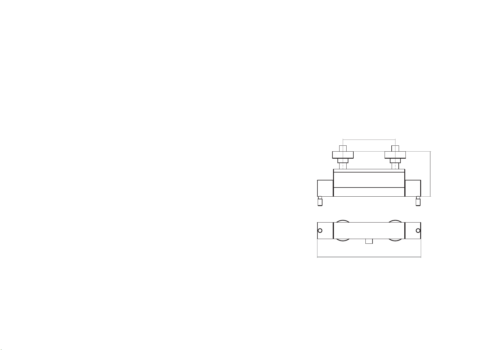
297mm
G1/2" BSP
129mm
150mm
KINETIC BOTTOM OUTLET BAR VALVE SHOWN

FITTING OPTION 1
1. Determine the correct position and orientation for the shower and screw the cranked connectors (2) into
the appropriate water supplies finished with a ½” BSP female adapter (not supplied). Hot on the left, cold
on the right with outlet positioned on the underside of body with SKN0601 or on the top of the body with
SKN0706.
2. Screw the shrouds/flanges (1) onto the cranked connectors.
3. To fit the body onto the wall, place the washers (3) into the connecting nuts (4) and tighten to the cranked
connectors (2). The connecting nuts (4) are secured to the mixer body by the retaining nuts (5). Note: No
back nuts or fixing plates are supplied. This shower valve is clip mounted it needs to be connected to and
supported by rigid pipe work.
TROUBLE-SHOOTING
If you require further assistance beyond the guide below contact the help line on 01225 303 900
AFTERCARE INSTRUCTIONS
Whilst this item has a high quality durable finish, it should nevertheless be treated with care. Surfaces should
be cleaned using only a soft damp cloth and clean water & dried using a soft cotton cloth. Bath / shower
cleaning products, even non-scratch ones could damage the finished surface.
MAINTENANCE
We advise that the valves, check valves and filters be regularly serviced particularly in hard water areas. The
check valves along with the filters are contained in the retaining nut. The water supplies must be isolated
remotely from the valve before removal. To access the check valves unscrew the connecting nuts joining the
mixer to the cranked connectors. Unscrew the retaining nuts (left hand thread) from the mixer and check their
conditions then reassemble and turn on water supply.
TMV2 approved valves shall be tested against the original set temperature results once a year. When testing is
due the following performance checks shall be carried out.
1. Measure the mixed water temperature at the outlet.
2. Carry out the cold fail-safe shut off test by isolating the cold water supply to the TMV, wait for 5 seconds if
water is still flowing check that the temperature is below 46 degrees C.
3. If there is no significant change to the set outlet temperature (+/- 2°C or less change from the original
setting) and the fail safe shut off is functioning, then the valve is working correctly and no further service
work is required.
If further maintenance should be required contact Tavistock for details. Please see contact details on the back
page of this document.
Problem
Shower will not run hot enough when first installed
Cold water running back through the valve into the hot
water system.
Solution
Maximum temperature needs adjusting, see temperature
setting guide
Check and clean the check valve cartridges and filters
located under the check valves.
1 2 3 4
MAX cut
diameter = 45mm
KINETIC BOTTOM OUTLET BAR VALVE SHOWN

FITTING OPTION 2
1 2 43
MAX cut
diameter = 45mm
15mm pipe
Olive
Fully tighten the threaded connector
so the olive compresses and rmly
locks the pipe in position.
Threaded connector
Cranked connector
Connecting nut
Check valve
Flow valve
Retaining nut - containing lters
(left hand thread)
KINETIC BOTTOM OUTLET BAR VALVE SHOWN
KINETIC BOTTOM OUTLET BAR VALVE SHOWN

1. 2.
SETTING THETEMPERATURE
The handle on the right of the valve controls the water temperature. To adjust the temperature:
1. Unscrew the handle arm (1) on the temperature handle (3) to reveal the handle grub screw (2). Using a
suitable allen key loosen the grub screw and carefully slide the handle off the thermostat spindle (5).
2. Remove the handle stop (4) from the thermostat spindle (5).
3. Rotate the thermostat handle (5) until the desired hot water temperature is reached. (TMV2 regulations
require a maximum temperature of no more than 44ºC)
4. Replace the handle stop (4) with the stop lug positioned just to the right of the cartridge stop (6). See
diagram below.
5. Replace the handle (3) back onto the thermostat spindle (5) and secure via the handle arm (2).
6. Test to ensure the desired maximum temperature is reached.
OPERATING
Increase flow
decrease
temperature
Increase
temperature
decrease flow
+
-
4
567
321
KINETIC BOTTOM OUTLET BAR VALVE SHOWN KINETIC BOTTOM OUTLET BAR VALVE SHOWN
This manual suits for next models
3
Table of contents
Popular Control Unit manuals by other brands


Mitsubishi Electric
Mitsubishi Electric AJ65DBTB1-32D user manual

Energeeks
Energeeks EG-MODPERS001 Quick installation guide

Edwards
Edwards LCPV16EKA instruction manual

BRUEL & KJAER
BRUEL & KJAER 3660-A-20 Series Setup guide

Emerson
Emerson Fisher FIELDVUE DVC6200 SIS Mounting instructions

Innodisk
Innodisk EMP2 SERIES user manual


