TAVLIT TDS User manual

1 Ver_2-08-22
TDS Semi-Automatic disc filters
Table of contents
•TDS technical information Pg. 2
•TDS 3”1 action –Installation and maintenance instructions Pg. 3
•TDS 2”1 action –Installation and maintenance instructions Pg. 5
•TDS 1 action filters- Periodic maintenance Pg. 7
•TDS 3”2 action –Installation and maintenance instructions Pg. 8
•TDS 2”2 action –Installation and maintenance instructions Pg. 10
•TDS 2 action filters- Periodic maintenance Pg. 12
•Trouble shooting all models Pg. 13
•Proper flushing of Discs Pg.14

2 Ver_2-08-22
Technical Specifications
•Available size: 2-3”.
•Max. working pressure: 10 bar.
•Max. flow rate:
o2”- 25 m3/h
o3” - 45 m3/h
•Available in 40 –140 mesh.
•Flushing flow rate:
o2 bar –9.0 m3/h
o3 bar - 12 m3/h
•Filtration area:1025 cm2
•Construction materials:
oPA+ GF, PP, PP+GF.
oO rings: EPDM
•Weight (empty): 9.3 Kg.

3 Ver_2-08-22
ADIR Semi–Automatic 3” filter TDS –Gen2
Installation and maintenance instructions 1 action
Box contents
•Main filter assembled –picture A
•Valve F/F 1/2" and Nipple M/M ½” – picture B
•Pressure indicator kit and fittings –picture C
oPressure indicator (Picture C-3).
oTube 6 mm length 25 cm (Picture C-4).
oTube 6 mm length 20 cm (Picture C-5).
oThreaded couplers 1/4"F x 2 (Picture C-6)
oConnectors 1/4"M to 6 mm elbow x 2
(Picture C-7).
oConnector 1/4"F to 6 mm elbow (Picture C-8).
oConnector 1/4"F to 6 mm adaptor (Picture C-9).
Assembly
•Connect the valve 1/2" with nipple 1/2” to the flush port
outlet (no need to use Teflon, valve is self-seal) –(Picture
B).
•Pressure indicator kit assembly:
oConnect two threaded couplers 1/4"F to filter
body top 1/4" outlets.
oConnect two 1/4"M to 6 mm elbow to the
threaded couplers 1/4"F.
oConnect 1/4"F to 6 mm elbow to the bottom of
the indicator (upstream - high pressure).
oConnect 1/4"F to 6 mm adaptor to side of the
indicator (downstream –low pressure).
oPress fit the indicator to the sockets on the filter
body.
oConnect 6 mm tube length 25cm from Filter inlet
port to indicator bottom (marked "+").
oConnect 6 mm tube length 20 cm from Filter
outlet port to indicator side (marked "-").
oHydraulic fittings may require Teflon to seal.
•Filter is ready for installation (Picture D)
Installation
•Filter can be installed in vertical position or at 90° to the
pipe, (Bottom of the cup pointing down or to the side).
•Ensure proper flow direction as clearly marked on the
filter.
•Make sure valve 1/2" is closed.
•It is recommended to install a shut off inlet valve before
the filter for maintenance.
•Filter is ready for first operation
740mm
A
645mm
B
235mm
C
485mm
D
Picture A
Before
assembly
Picture B
Picture C
Picture D
After
assembly

4 Ver_2-08-22
First Operation
•Open the water source and inlet maintenance valve and check for leaks.
•Perform 2-3 flushing cycles as outlined below.
•Filter is ready for use.
Flushing the filter
•The disc element needs to be cleaned when the
head loss across the filter reaches 0.5-0.7 bar and
the red pin is pushed out from the pressure
indicator (Picture E).
•Turn the handle ¼+ of a turn until the stop
(Picture F).
•Wait 15–30 seconds.
•Turn the filter handle back (Picture F).
•Open the valve 1/2" for 10 seconds and close
(Picture G).
Please note: the strength required to turn the handle
may vary according to water pressure, the water
quality and its source.
Picture F
Picture E
Picture G

5 Ver_2-08-22
ADIR Semi–Automatic 2” filter TDS –Gen2
Installation and maintenance instructions 1 action
Box contents
•Main filter assembled –picture A
•Valve F/F 1/2" and Nipple M/M ½” – picture B
•Pressure indicator kit and fittings –picture C
oPressure indicator (Picture C-3).
oTube 6 mm length 25 cm (Picture C-4).
oTube 6 mm length 20 cm (Picture C-5).
oConnector 1/4"F to 6 mm adaptor x 2 (Picture C-
6)
oConnector 1/4"F to 6 mm elbow (Picture C-7).
oConnector 1/4"F to 6 mm adaptor (Picture C-8).
Assembly
•Connect the valve 1/2" with nipple 1/2” to the flush port
outlet (no need to use Teflon, valve is self-seal) –(Picture
B).
•Pressure indicator kit assembly:
oConnect two adaptors 1/4"F to 6 mm to filter
body top 1/4" outlets.
oConnect 1/4"F to 6 mm elbow to the bottom of
the indicator (upstream - high pressure).
oConnect 1/4"F to 6 mm adaptor to side of the
indicator (downstream –low pressure).
oPress fit the indicator to the sockets on the filter
body.
oConnect 6 mm tube length 25cm from Filter inlet
port to indicator bottom (marked "+").
oConnect 6 mm tube length 20 cm from Filter
outlet port to indicator side (marked "-").
oHydraulic fittings may require Teflon to seal.
•Filter is ready for installation (Picture D)
Installation
•Filter can be installed in vertical position or at 90° to the
pipe, (Bottom of the cup pointing down or to the side).
•Ensure proper flow direction as clearly marked on the
filter.
•Make sure valve 1/2" is closed.
•It is recommended to install a shut off inlet valve before
the filter for maintenance.
•Filter is ready for first operation
740mm
A
645mm
B
235mm
C
485mm
D
Picture B
Picture C
Picture D
After
assembly
Picture A
Before
assembly

6 Ver_2-08-22
First Operation
•Open the water source and inlet maintenance valve and check for leaks.
•Perform 2-3 flushing cycles as outlined below.
•Filter is ready for use.
Flushing the filter
•The disc element needs to be cleaned when the
head loss across the filter reaches 0.5-0.7 bar and
the red pin is pushed out from the pressure
indicator (Picture E).
•Turn the handle ¼+ of a turn until the stop
(Picture F).
•Wait 15–30 seconds.
•Turn the filter handle back (Picture F).
•Open the valve 1/2" for 10 seconds and close
(Picture G).
Please note: the strength required to turn the handle
may vary according to water pressure, the water
quality and its source.
Picture F
Picture E
Picture G

7 Ver_2-08-22
Periodic Maintenance 1 Action filters
Warning:
•Never open the filter under pressure!
to release pressure turn the handle to flush position and
open the flush valve 1/2"
•Before servicing the filter make sure it is empty of water
and the inlet valve is closed.
Secondary flush port cleaning
•The secondary flush port should be examined every 30 days or if
the flush cycle does not reduce the head loss (filter does not
flush effectively).
•Disassemble the flush valve 1/2" F with nipple 1/2" (Picture H-1).
•Rotate the screen disc counterclockwise and pull out (Picture I)
Make sure the screen is intact and has no tears
•Flush thoroughly under stream of water.
•Return the screen disc to its place and rotate clockwise until it
stops.
•Assemble the nipple with the flush valve and close.
Discs manual cleaning
•The Discs should be cleaned manually at the beginning of the
irrigation season and every 90 days thereafter or if the flush cycle
does not reduce the head loss (filter does not flush effectively).
•Open the tightening ring (Picture H-2) counterclockwise pull it down
and put aside.
•Release the filter cup (Picture H-3) by pulling down and nudging from
side to side.
•Open the lock bolt (Picture J-4) with screwdriver and remove piston
(Picture J-5) and ratchet (Picture J-6).
•Remove the O-ring carefully avoiding damage (Picture K-7).
•Remove the discs carefully (Picture K-8).
•Flush discs thoroughly under stream of water. Make sure hard
adhesives are removed.
•In case the discs are still not clean perform a manual flushing with
HCL solution, see instructions doc. attached.
•Return all discs to the spine –make sure you returned all of them
(Picture K-8).
•Return the O-ring carefully avoiding damage (Picture K-7).
•Return the piston with ratchet and close lock bolt (Picture J-4) with
screwdriver.
•Tighten the cup (Picture H-3) to the filter body and position the cup
protrusion opposite the socket in the filter body. (Picture H)
•Return the locking ring (Picture H-2) to its place and tighten by hand.
Picture J
Picture K
Picture I
Picture H

8 Ver_2-08-22
ADIR Semi–Automatic 3” filter TDS –Gen2
Installation and maintenance instructions 2 action
Box contents
•Main filter assembled –picture A
•Valve 2" FF –picture L
•Valve F/F 1/2" and Nipple M/M ½” – picture B
•Pressure indicator kit and fittings –picture C
oPressure indicator (Picture C-3).
oTube 6 mm length 25 cm (Picture C-4).
oTube 6 mm length 20 cm (Picture C-5).
oThreaded couplers 1/4"F x 2 (Picture C-6)
oConnectors 1/4"M to 6 mm elbow x 2
(Picture C-7).
oConnector 1/4"F to 6 mm elbow (Picture C-8).
oConnector 1/4"F to 6 mm adaptor (Picture C-9).
Assembly
Connect the 2” flush valve to the bottom of the filter cup,
(no need to use Teflon, valve is self-seal) –Picture E
Make sure handle open position is away from filter cup.
•Connect the valve 1/2" with nipple 1/2” to the flush port
outlet (no need to use Teflon, valve is self-seal) –
(Picture B).
•Pressure indicator kit assembly:
oConnect two threaded couplers 1/4"F to filter
body top 1/4" outlets.
oConnect two 1/4"M to 6 mm elbow to the
threaded couplers 1/4"F.
oConnect 1/4"F to 6 mm elbow to the bottom of
the indicator (upstream - high pressure).
oConnect 1/4"F to 6 mm adaptor to side of the
indicator (downstream –low pressure).
oPress fit the indicator to the sockets on the filter
body.
oConnect 6 mm tube length 25cm from Filter inlet
port to indicator bottom (marked "+").
oConnect 6 mm tube length 20 cm from Filter
outlet port to indicator side (marked "-").
oHydraulic fittings may require Teflon to seal.
•Filter is ready for installation (Picture D)
Installation
•Filter can be installed in vertical position or at 90° to the
pipe, (Bottom of the cup pointing down or to the side).
•Ensure proper flow direction as clearly marked on the
filter.
•Make sure valve 1/2" is closed.
•It is recommended to install a shut off inlet valve before
the filter for maintenance.
•Filter is ready for first operation
950mm
A
795mm
B
235mm
C
595mm
D
Picture A
Before
assembly
Picture B
Picture C
Picture D After
assembly
Picture L

9 Ver_2-08-22
First Operation
•Open the water source and inlet maintenance valve and check for
leaks.
•Perform 2-3 flushing cycles as outlined below.
•Filter is ready for use.
Flushing the filter
•The disc element needs to be cleaned when the
head loss across the filter reaches 0.5-0.7 bar and
the red pin is pushed out from the pressure
indicator (Picture E).
•Open the bottom valve 2" (Picture M)
•Turn the handle ¼+ of a turn until the stop
(Picture F).
•Wait 15–30 seconds.
•Turn the filter handle back (Picture F).
•Close the bottom flush valve (Picture M)
•Open the valve 1/2" for 10 seconds and close
(Picture G).
Please note: the strength required to turn the handle
may vary according to water pressure, the water
quality and its source.
Picture F
Picture E
Picture G
Picture M

10 Ver_2-08-22
ADIR Semi–Automatic 2” filter TDS –Gen2
Installation and maintenance instructions 2 action
Box contents
•Main filter assembled –picture A
•Valve 2" FF –picture L
•Valve F/F 1/2" and Nipple M/M ½” – picture B
•Pressure indicator kit and fittings –picture C
oPressure indicator (Picture C-3).
oTube 6 mm length 25 cm (Picture C-4).
oTube 6 mm length 20 cm (Picture C-5).
oConnector 1/4"F to 6 mm adaptor x 2
(Picture C-6)
oConnector 1/4"F to 6 mm elbow (Picture C-8).
oConnector 1/4"F to 6 mm adaptor (Picture C-9).
Assembly
Connect the 2” flush valve to the bottom of the filter cup,
(no need to use Teflon, valve is self-seal) –Picture E
Make sure handle open position is away from filter cup.
•Connect the valve 1/2" with nipple 1/2” to the flush port
outlet (no need to use Teflon, valve is self-seal) –(Picture
B).
•Pressure indicator kit assembly:
oConnect two adaptors 1/4"F to 6 mm to filter
body top 1/4" outlets.
oConnect 1/4"F to 6 mm elbow to the bottom of
the indicator (upstream - high pressure).
oConnect 1/4"F to 6 mm adaptor to side of the
indicator (downstream –low pressure).
oPress fit the indicator to the sockets on the filter
body.
oConnect 6 mm tube length 25cm from Filter inlet
port to indicator bottom (marked "+").
oConnect 6 mm tube length 20 cm from Filter
outlet port to indicator side (marked "-").
oHydraulic fittings may require Teflon to seal.
•Filter is ready for installation (Picture D)
Installation
•Filter can be installed in vertical position or at 90° to the
pipe, (Bottom of the cup pointing down or to the side).
•Ensure proper flow direction as clearly marked on the
filter.
•Make sure valve 1/2" is closed.
•It is recommended to install a shut off inlet valve before
the filter for maintenance.
•Filter is ready for first operation
950mm
A
795mm
B
235mm
C
595mm
D
Picture B
Picture C
Picture D After
assembly
Picture L
Picture A
Before
assembly

11 Ver_2-08-22
First Operation
•Open the water source and inlet maintenance valve and check for
leaks.
•Perform 2-3 flushing cycles as outlined below.
•Filter is ready for use.
Flushing the filter
•The disc element needs to be cleaned when the
head loss across the filter reaches 0.5-0.7 bar and
the red pin is pushed out from the pressure
indicator (Picture E).
•Open the bottom valve 2" (Picture M)
•Turn the handle ¼+ of a turn until the stop
(Picture F).
•Wait 15–30 seconds.
•Turn the filter handle back (Picture F).
•Close the bottom flush valve (Picture M)
•Open the valve 1/2" for 10 seconds and close
(Picture G).
Please note: the strength required to turn the handle
may vary according to water pressure, the water
quality and its source.
Picture F
Picture E
Picture G
Picture M

12 Ver_2-08-22
Periodic Maintenance 2 Action Filters
Warning:
•Never open the filter under pressure!
to release pressure turn the handle to flush position and
open the flush valve 1/2"
•Before servicing the filter make sure it is empty of water
and the inlet valve is closed.
Secondary flush port cleaning
•The secondary flush port should be examined every 30 days or if
the flush cycle does not reduce the head loss (filter does not
flush effectively).
•Disassemble the flush valve 1/2" F with nipple 1/2" (Picture H-1).
•Rotate the screen disc counterclockwise and pull out (Picture I)
Make sure the screen is intact and has no tears
•Flush thoroughly under stream of water.
•Return the screen disc to its place and rotate clockwise until it
stops.
•Assemble the nipple with the flush valve and close.
Discs manual cleaning
•The Discs should be cleaned manually at the beginning of the
irrigation season and every 90 days thereafter or if the flush
cycle does not reduce the head loss (filter does not flush
effectively).
•Open the tightening ring (Picture H-2) counterclockwise, pull it
down and put aside.
•Release the filter cup (Picture H-3) by pulling down and nudging
from side to side.
•Open the lock bolt (Picture J-4) with screwdriver and remove
piston (Picture J-5) and ratchet (Picture J-6).
•Remove the O-ring carefully avoiding damage (Picture K-7).
•Remove the discs carefully (Picture K-8).
•Flush discs thoroughly under stream of water. Make sure hard
adhesives are removed.
•In case the discs are still not clean perform a manual flushing with
HCL solution, see instructions doc. attached.
•Return all discs to the spine –make sure you returned all of them
(Picture K-8).
•Return the O-ring carefully avoiding damage (Picture K-7).
•Return the piston with ratchet and close lock bolt (Picture J-4) with
screwdriver.
•Tighten the cup (Picture H-3) to the filter body and position the cup
protrusion opposite the socket in the filter body. (Picture H)
•Return the locking ring (Picture H-2) to its place and tighten by hand.
Picture H
Picture J
Picture K
Picture I

13 Ver_2-08-22
Trouble shooting for all models
•Head loss is not decreasing after flushing cycle:
oCheck that the pressure is not below 2 bar.
oCheck that there is no disturbance to the flushing flow.
oFlush the internal screen by opening its valve 1/2".
oRepeat the flushing cycle again, do not forget to open the filter valve 2" before turning the handle.
•Filter is still not clean:
oClean the internal screen: see Periodic Maintenance –Secondary flush
port cleaning (outlined below)
oClean discs manually: see Periodic Maintenance –Discs manual
cleaning (outlined below)
•Filter handle is not turning
oCheck that the bottom valve 2" is fully open before turning the handle.
oCheck that water flows through the bottom valve 2".
oCheck that inlet pressure is lower than 6 bars
•Filter handle is still not turning
oPartly close the inlet maintenance valve and turn the handle
oPerform a flushing cycle, do not forget to open the filter valve 2" before turning the handle.
oOpen the inlet maintenance valve

14 Ver_2-08-22
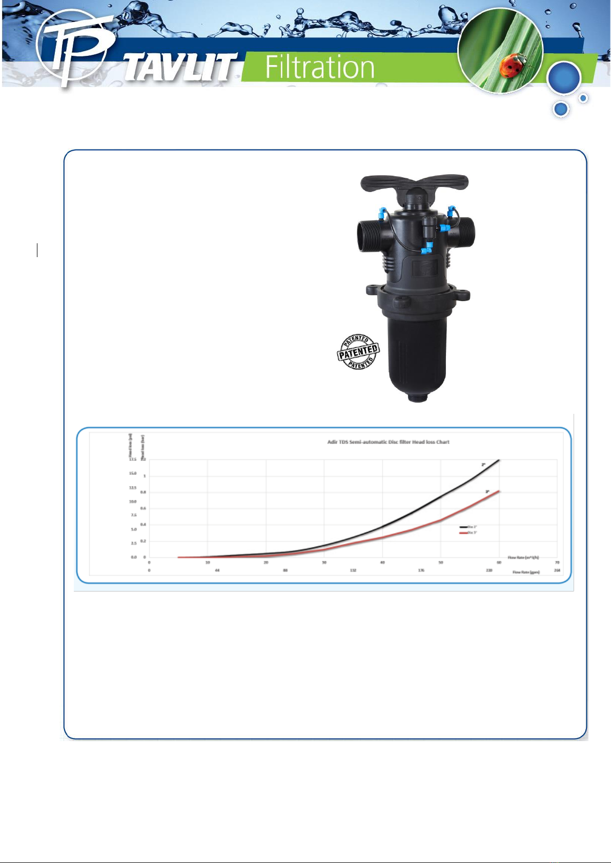
TDS - Proper flushing of discs
It is recommended to clean the discs before and after irrigation season to ensure proper functioning of the filter
for many years. Manual flushing is required when the filter is clogged and flushing process does not clean it
properly.
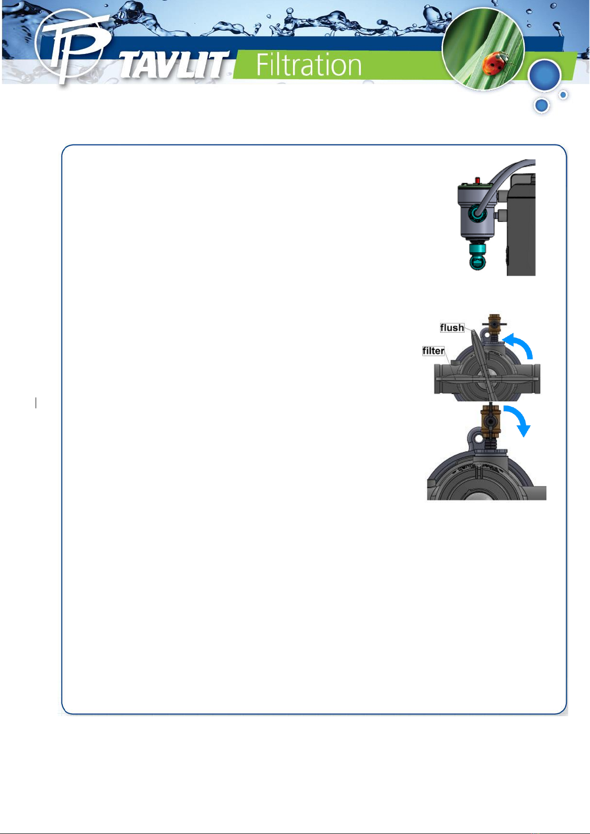
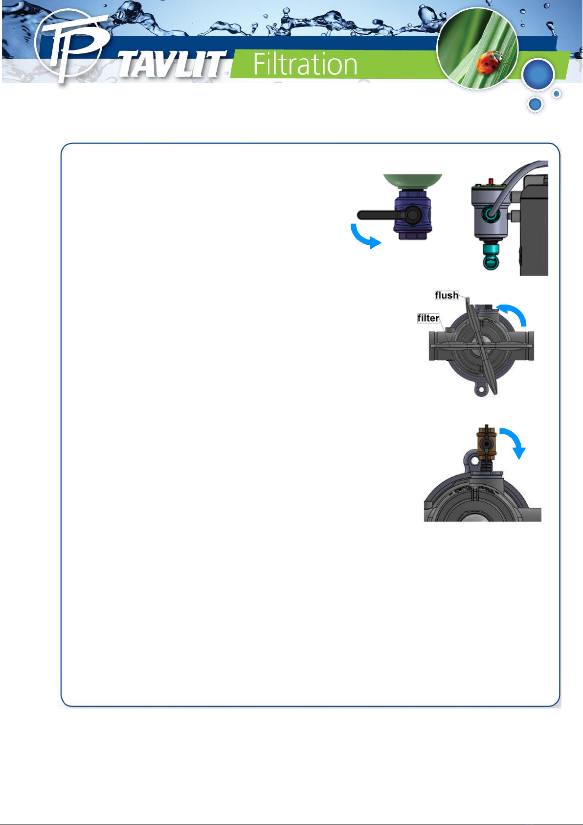
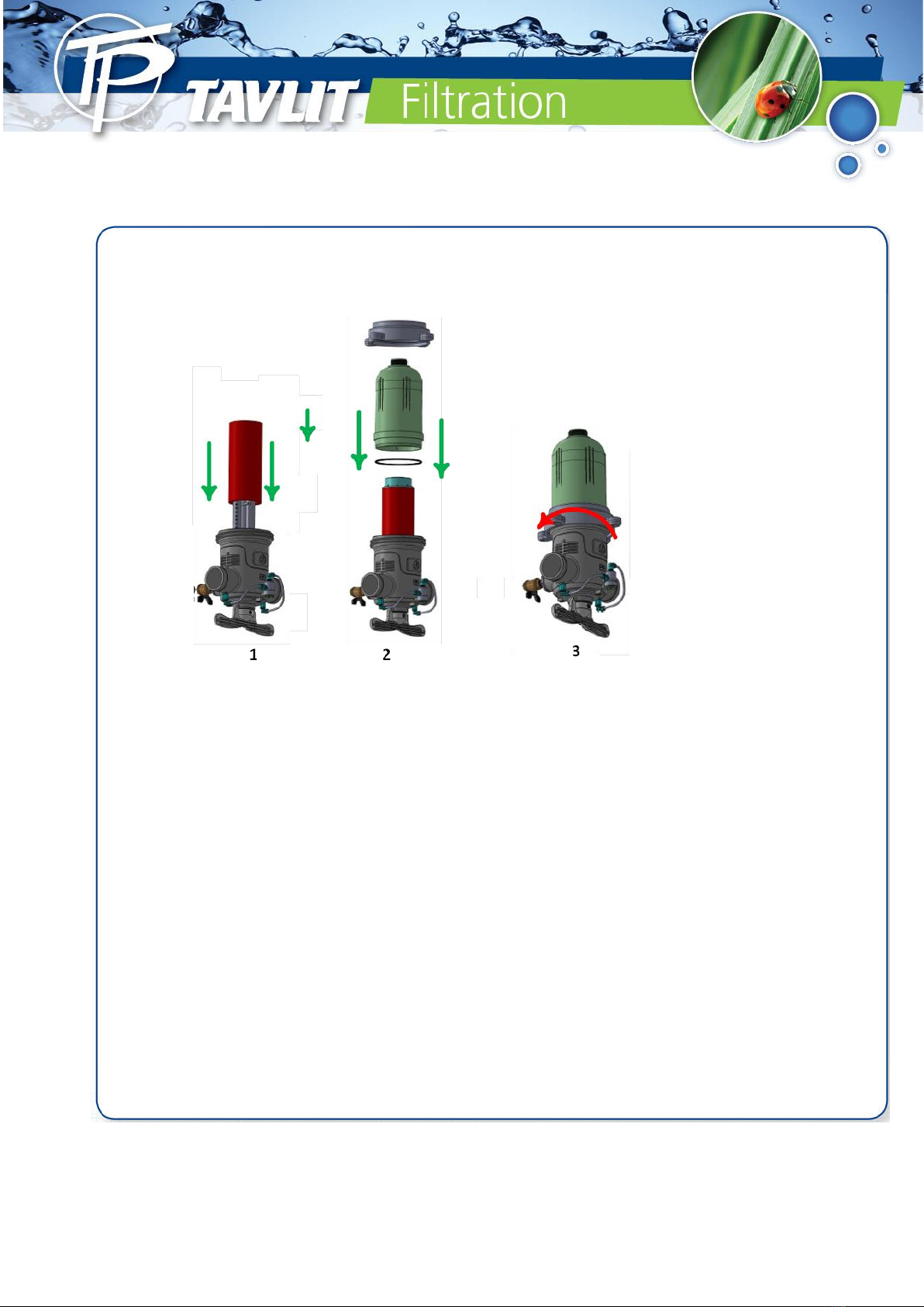
•Before opening the filter cup close the inlet valve of the system and release the pressure in the filter battery
by opening the drain valve.
•Release the disc cap and when the discs are loose on the spine perform a manual flushing using a water
hose to flush the discs in high pressure directing the flow tangentially to the spine.
Never open the filter under pressure
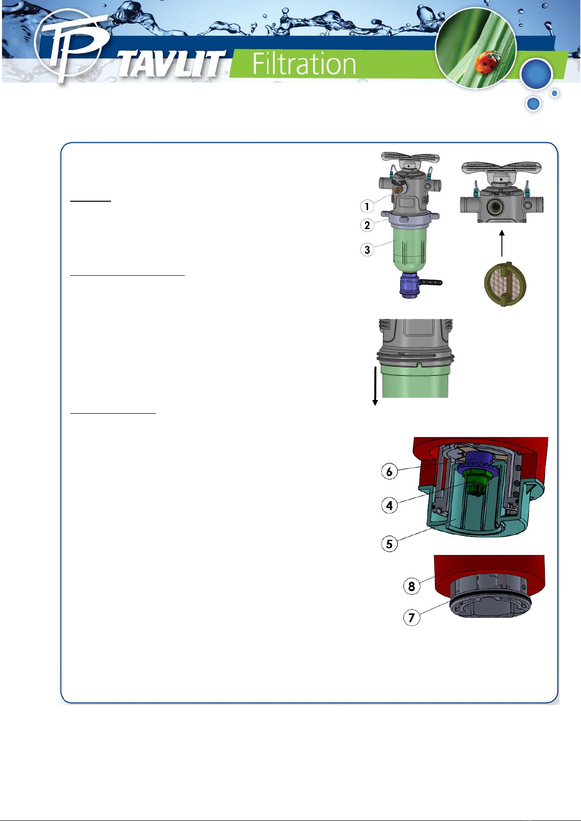
•Dismentle discs from the spine.
•Visually check for twisted or worn out discs and replace if required.
•In case of chemical deposits on discs grooves, tie each disc set with a nylon rope and soak the discs into an
appropriate solution –see below. After treatment, rinse thoroughly with fresh water.
•Reassemble the discs on the spines and back in the filter, then close and tighten filter body. Ensure head
loss does not exceed 2-3m.
Detailed explanation of chemical treatment of the discs
Several types of deposits can clog the disc. These can be:
•Organic matter, it will be brown or green and will look like mocus.
•Metal oxide - iron in rust color or managanese in black color.
•Carbonaes - white or grey in color
•Combination of several deposits.
Perform cleaning in a properly ventilated area and use gloves, safety glasses and
protective clothes.
6.1 Preparing the solution for immersing the discs
For organic material use Sodium Hypoclorite
•Mix 5 liters of Hypoclorite (10% concentration) with 5 liters of water. The solution is 5% concentrated.
•Tie the discs with a rope and soak in the solution for 8 hours- then rinse with water thoroughly.
•After installing the discs back in the filter perform several flushing cycles.
For carbonate and iron deposits use Hydroclorite Acid.
•Mix 2 liters of Hypoclorite (30% concentration) with 10 liters of water. The solution is 5% concentrated.
•Tie the discs with a rope and soak in the solution for 8 hours- then rinse with water thoroughly.
For complex deposits
•In case the user is not sure about the type of the deposits he should run a test.
•Put several discs in Sodium ypocloride solution and seveal in a Hydroclorite Acid solution, (prepare the
solution as explained above).
•If one of the dolutions cleans the discs perform cleaning process in that solution.
•If none of the solutions cleaned the discs completely replace the discs that were immersed in the
Hypocloride acid into the Sodium Hypocloride and vise versa and watch which treatment cleaned the discs.
This is the process to follow with all discs.
•If none of the treatments cleaned the discs properly send several discs to a laboratory to get a diagnosis of
th edeposits and the proprer treatment needed in order to clean them.

15 Ver_2-08-22
Step 1 Step 2
Release the filter clamp Remove the filter cup and
then remove the O-ring carefully
Step 3 Step 4
Remove the dics Place the discs in HCL solution

16 Ver_2-08-22
Step 5
Reassemble the filter
After installing the discs back in the filter perform several flushing cycles.
Table of contents
Other TAVLIT Water Filtration System manuals
Popular Water Filtration System manuals by other brands

Canature
Canature 475 Pro Series Installation & operation manual

Omnifilter
Omnifilter SFM2 installation instructions

LG
LG WCD56US2 owner's manual

Filtreco
Filtreco Basic combi drum 25 user manual

Magus
Magus BASIKA rho NS 2 Installation, operating and maintenance instructions

Astral Pool
Astral Pool Combo 27413 Instruction and operation manual