manuals.online logo
Brands
  1. Home
  2. •
  3. Brands
  4. •
  5. Tavolo
  6. •
  7. Indoor Furnishing
  8. •
  9. Tavolo 411/78.1100.22E User manual

Tavolo 411/78.1100.22E User manual

ISTRUZIONI DI MONTAGGIO
ASSEMBLY INSTRUCTIONS
MODELLI
MODELS:
411/78.1100.22E Lunch per modulo mm 600 spalle: mm 15-20
Lunch for cabinet mm 600 sides: mm 15-20
411/78.1110.22E Lunch per modulo mm 900 spalle: mm 15-20
Lunch for cabinet mm 900 sides: mm 15-20
411/78.1120.22E Lunch per modulo mm 1200 spalle 15-20
Lunch for cabinet mm 1200 sides: mm 15-20
CONTENUTO DELLA CONFEZIONE
INCLUDED IN THE PACKAGING
GUIDE PREASSEMBLATE
PRE ASSEMBLED SLIDES
Maniglia mm 402/702/1002
Handle mm 402/702/1002
La lunghezza della maniglia dipende dalla largehezza della base
Handle length depends on cabinet width
SACCHETTO ACCESSORI
ACCESSORIES
- A - Vite TCCE M6x60 - Socked head cap screw M6x60 (x 4)
- B - Vite TCCE M6x12 - Socked head cap screws M6x12 (x 8)
- E - Chiave esa. da 5 - n°5 Allen key (x 1)
1/7
- D - Bussola in ottone mm 12x8 M6 - Brass bush 12x8 M6 (x 12)
- C - Vite TCCE M5x6 - Socked head cap screws M5x6 (x 2)
- F - Chiave esa. da 4 - n°4 Allen key (x 1) REV 03 (06-14)
A
MODELLO MODEL MODULO MODULE L1 L2 L3 L4
411/78.1100.22E 600 570 436 402 488
411/78.1110.22E 900 870 736 702 788
411/78.1120.22E 1200 1170 1036 1002 1088
A
DIMENSIONI DI MASSIMA
GENERAL DIMENSIONS
2/7
INGOMBROINALTEZZA:60
OVERALLHEIGTH
LARGHEZZA TOTALE (L1)
OVERALL WIDTH
529
787CORSA:
OPENING
INTERASSEFORIFISSAGGIOPIANO(L4)
DISTANCEBETWEENFIXINGPLANEHOLES
60
67
VITE PER FISSAGGIO PIANO
SCREW FOR PLANE FIXING
529
DISTANZA TRA LE GUIDE (L2)
SPACE BETWEEN THE SLIDES
LUNGHEZZAMANIGLIA(L3)
HANDLELENGTH
L4 = L1 - 82
L3 = L1 - 158
B-B
DIMENSIONE - DIMENSION SIMBOLO - SYMBOL
LUCE VERTICALE VERTICAL FREE SPACE H MIN: 62+Sx2
SPESSORE PIANI/SPALLE PLANE/SIDE THICKNESS S 15-20
PROFONDITA' INTERNA INTERNAL FREE SPACE P MIN: 540
LARGHEZZA PIANI - PLANES W IDTH Z L - Sx2 - 3
LA RGE HZZA MODULO - CA BINET W IDTH L
B B
DIMENSIONI GENERALI MOBILE
GENERAL CABINET DIMENSIONS
755
529
R440
LUCEVERTICALE(H)
VERTICALFREESPACE
PROFONDITA' INTERNA (P)
INTERNAL FREE SPACE
PIANO RIBALTABILE
TILTING PLANE
PIANO FISSO
FIXED PLANE
3/7
540
LARGEZZAMODULO(L)
CABINETWIDTH(L)
440
POSIZIONE FORI FISSAGGIO MECANISMO
HOLES FOR MECHANISM POSITION
POSIZIONE LATO SUPERIORE GUIDE
TOP OF THE SLIDES
733
4/7
50 448
114 320
50
716*
16
* PER BILANCIARE LA FLESSIONE DEL MECCANISMO, SUGGERIAMO DI ESEGUIRE LE FORATURE
PER IL FISSAGGIO GUIDA CON UNA DIFFERENZA DI 2-3 mm TRA LATO ANTERIORE (QUOTA 716 PASSA
A 717.5) e POSTERIORE (QUOTA 716 PASSA A 714.5)
To compensate the mechanism flexibility, we suggest to drill the holes with a difference of 2-3 mm between
the anterior holes (dimension 717.5 instead of 716) and the posterior ones
(dimensione 714.5 instead of 716)
RICAVARE SU CIASCUNA SPALLA DEL MOBILE 4 FORI DIAM. 8x13
PER LE BUSSOLE M6 INCLUSE NELLA CONFEZIONE
LA QUOTA INDICATA DI 50 mm, LASCIA UNO SPAZIO LIBERO
TRA GUIDA E PIANETTO SOTTOSTANTE DI CIRCA 25 mm
DRILL ON EACH CABINET SIDE FOUR DIAM. 8x13 HOLES FOR
THE INCLUDED M6 BRASS BUSHES.
THE INDICATED 50 mm DIMENSION LEAVES A FREE SPACE
BETWEN THE BOTTOM OF THE SLIDES
AND THE PLANE OF ABOUT 25 mm
- D Bussola in ottone M6 mm 12x8 (x 8)
M6 mm 12x8 Brass bushes
EE
E
Per montare il meccanismo bisogna prima
sfilare le due guide più esterne. Per farlo
svitare la vite posta alla fine delle seconde
guide e sfilare da dietro le guide esterne.
A questo punto le guide esterne si fissano alla
spalla del mobile utilizzando le incluse viti
TCCE M6x12 (B).
Per completare l'operazione, infilare ora il
meccanismo sulle guide esterne e serrare le
viti prima svitate.
Dopo aver rimontato le guide, avvitare sotto
ciascuna guida esterna la vite M5x6 (C) che
serve per bloccarne l'apertura.
To mount the mechanism on the cabinet, it is
necessary first to disassemble the two
external slides. To do this, unsrews the two
screws in the rear of the second element. Now
fix the esternal slides to the cabinet sides
using the included M6x12 (B) screws. Last,
insert agin the mechanism on the external
slides and thigthen the two indicated screws.
Finally you must screw under the final part of
each external slide the indicated M5x6 (C)
screw.
GUIDA ESTERNA
EXTERNAL SLIDE
GUIDA ESTERNA
EXTERNAL SLIDE
VITE DA ALLENTARE
SCREW TO BE UNSCREWED
VITE DA ALLENTARE
SCREW TO BE UNSCREWED
MONTAGGIO DEL MECCANISMO SUL MOBILE
MOUNTING OF THE MECHANISM ON THE CABINET
- B - Vite TCCE M6x12 (x 8)
Socked head cap screw M6x12 (x 8)
- E - Chiave esagonale da 5
n°5 Allen key
B
5/7
C DA MONTARE COME ULTIMA COSA
TO BE SCREWED AT THE END OF ASSEMBLY
- C - Vite TCCE M5x6 (x 2)
Socked head cap screw M5x6 (x 2)
- F - Chiave esagonale da 4
n°4 Allen key
6/7
DIMENSIONI PIANETTI
PLANES DIMENSIONS
Il piano fisso puè essere montato utilizzando
le quattro viti TCCE M6x60 (A) fornite a corredo
inserite negli appositi fori sulle guide centrali.
The fixed plan can be mounted using the supplied
four socked head screws M6x60 (A) inserted in proper
holes on the central slides.
- A - Vite TCCE M6x60 (x 4)
Socked head cap screw M6x60
- E - Chiave esa. da 5
n°5 Allen key (x 1)
29 280 220
Z(SIVEDAPAG.2E3)
(SEEPAGE2AND3)
L4(SIVEDAPAG.2E3)
(SEEPAG.2AND3)
39,539,5
VISTA DAL BASSO
BOTTOM VIEW
PIANO FISSO
FIXED PLANE
PIANO FISSO
FIXED PLANE
PIANO RIBALTABILE
TILTING PLANE PIANO RIBALTABILE
TILTING PLANE
440
Z(SIVEDAPAG.2E3)
(SEEPAG.2AND3)
D
A
- D Bussola in ottone M6 mm 12x8 (x 8)
M6 mm 12x8 Brass bushes
REALIZZARE SOTTO IL PIANO FISSO n. 4 FORI DIAM. 8x13
PER LE BUSSOLE M6 ( D)
DRILL UNDER THE FIXED PLANE n. 4 DIAM. 8 x 13 HELES FOR
M6 BRASS BUSHES (D)
F
SPINGERE VERSO INTERNO LA LEVA ROSSA PER
CHIUDERE IL MECCANISMO
PUSH TEH RED LEVER TO CLOSE THE MECHANISM
7/7
SEQUENZA DI FUNZIONAMENTO
FUNCTIONING STEPS
CHIUSO
CLOSED ESTRAZIONE GUIDE
SLIDES OPENING ROTAZIONE PIANETTO
PLANE TILTING
APERTO
OPENED

This manual suits for next models

2

Other Tavolo Indoor Furnishing manuals

Tavolo 411/78.1150.22 User manual

Tavolo

Tavolo 411/78.1150.22 User manual

Tavolo 411/78.1100.22E User manual

Tavolo

Tavolo 411/78.1100.22E User manual

Popular Indoor Furnishing manuals by other brands

Jula Hard Head 343-585 User instructions
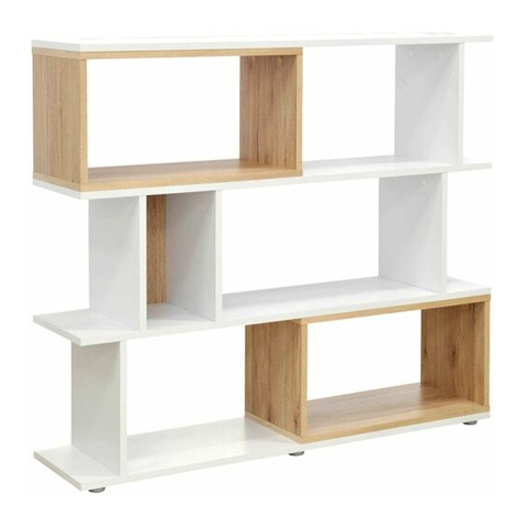
Jula

Jula Hard Head 343-585 User instructions

Emmezeta CUBIX MINI Assembling instructions

Emmezeta

Emmezeta CUBIX MINI Assembling instructions

HULALA HOME TVSLS0462 manual

HULALA HOME

HULALA HOME TVSLS0462 manual
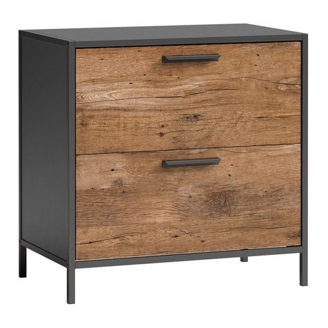
Teknik Boulevard Cafe 5427345 Instruction booklet

Teknik

Teknik Boulevard Cafe 5427345 Instruction booklet

Northbeam SLF0330112010 Assembly instructions

Northbeam

Northbeam SLF0330112010 Assembly instructions

Presidential Billiards CARMEL Assembly instructions
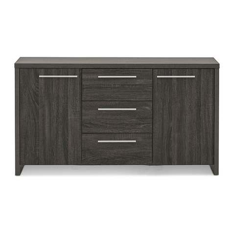
Presidential Billiards

Presidential Billiards CARMEL Assembly instructions

Amart Furniture Summit 51838 Assembly instruction
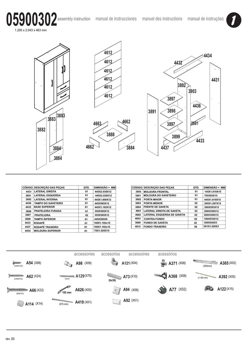
Amart Furniture

Amart Furniture Summit 51838 Assembly instruction

Zanzini 05900302 Assembly instruction

Zanzini

Zanzini 05900302 Assembly instruction
The Container Store Kelsey Assembly instructions

The Container Store

The Container Store Kelsey Assembly instructions

EHRET Voletronic io Installation and operating instructions

EHRET

EHRET Voletronic io Installation and operating instructions

Hay CPH25 instruction manual

Hay

Hay CPH25 instruction manual

GrainWood Brushed Walnut MC1605 Assembly instructions
GrainWood

GrainWood Brushed Walnut MC1605 Assembly instructions

Steelcase 462 Leap V2 quick start guide
Steelcase

Steelcase 462 Leap V2 quick start guide

Lightolier 4A23 specification

Lightolier

Lightolier 4A23 specification
Contractors Wardrobe uDivide Parts and Assembly Instructions
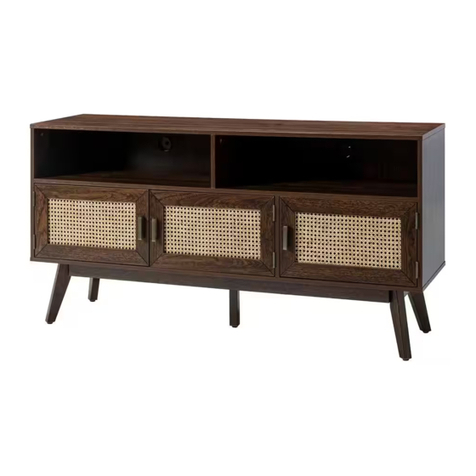
Contractors Wardrobe

Contractors Wardrobe uDivide Parts and Assembly Instructions

JAYDEN CREATION TVSBSD0453 brochure

JAYDEN CREATION

JAYDEN CREATION TVSBSD0453 brochure
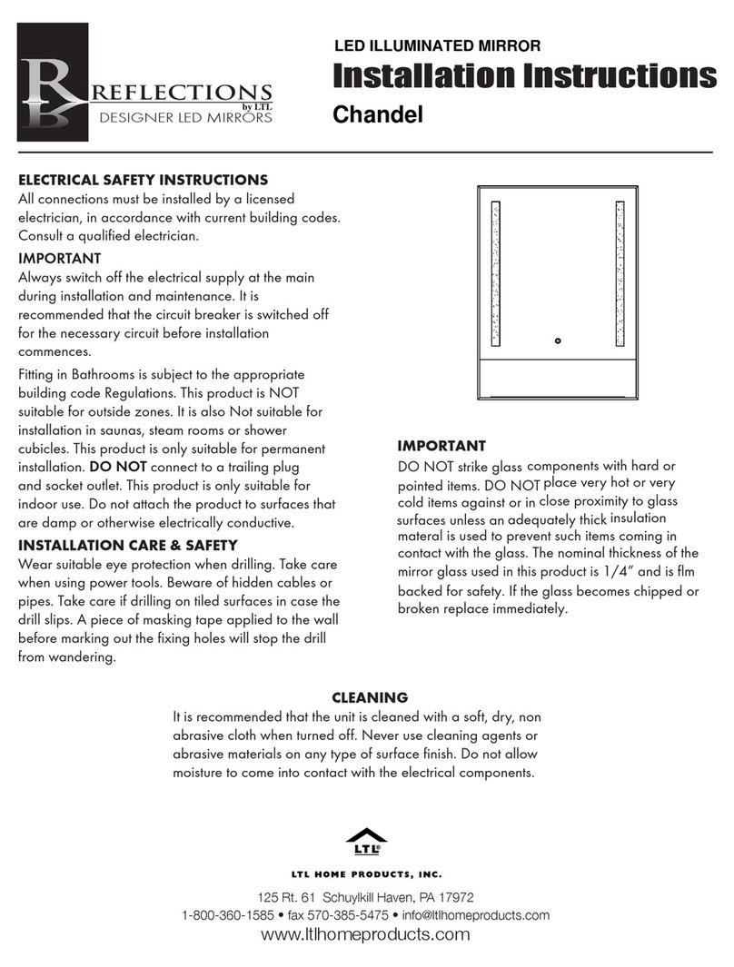
LTL Home Products Reflections Chandel installation instructions

LTL Home Products

LTL Home Products Reflections Chandel installation instructions

Furniture of America CM3351PT-5PK Assembly instructions

Furniture of America

Furniture of America CM3351PT-5PK Assembly instructions

manuals.online logo
manuals.online logoBrands
  • About & Mission
  • Contact us
  • Privacy Policy
  • Terms and Conditions

Copyright 2025 Manuals.Online. All Rights Reserved.