Taxitronic Skyglass TX80 User manual

INSTALLATION MANUAL TX80 SKYGLASS INTERFACOM, S.A.U. 18.02.19
Inst TX80_Skyglass_003_en.doc 08/03/2017
INSTALLATION MANUAL
TAXITRONIC TX80 SKYGLASS

INSTALLATION MANUAL TX80 SKYGLASS INTERFACOM, S.A.U.
Inst TX80_Skyglass_003_en.doc 2
GENERAL INDEX
1. INTRODUCTION...............................................................................................................................3
2. INSTALACIÓN SAM.........................................................................................................................3
3. MOUNTING .......................................................................................................................................3
3.1. MOUNTING AND LOCATION OF TX80................................................................................3
3.2. MOUNTING AND LOCATION OF SKYGLASS.....................................................................4
4. ELECTRICAL INSTALLATION .......................................................................................................5
5. SEALING..........................................................................................................................................11
5.1. TX80 SEALING ...........................................................................................................................11
5.2. SKYGLASS SEALING ................................................................................................................12
6. TECHNICAL CHARACTERISTICS................................................................................................12
7. IMPULSE GENERATOR.................................................................................................................14
7.1. INTRODUCTION.........................................................................................................................14
7.2. INSTALLATION..........................................................................................................................14
7.2.1. ASSEMBLY OF THE SPEEDOMETER CABLE AND PULSE GENERATOR ..................14
7.2.2. CABLE CONNECTION, COVER CLOSING AND PULSE GENERATOR SUPPORT .......16
7.3. SEALING (Drawing 11) ...............................................................................................................17
7.4. TECHNICAL CHARACTERISTICS ...........................................................................................17
8. VEHICLES WITH ELECTRONIC IMPULSE SIGNAL..................................................................17

INSTALLATION MANUAL TX80 SKYGLASS INTERFACOM, S.A.U.
Inst TX80_Skyglass_003_en.doc 3
1. INTRODUCTION
This document describes the installation and parameterization of the taximeter
TAXITRONIC TX80 SKYGLASS.
2. INSTALACIÓN SAM
To introduce SAM card the device must be opened, then introduce SAM card in the
skyglass groove as there is shown on the plane
To configure the SAM card, the toolkit manual (SIM/SAM configuration section)
indications must be followed. This process must be done after the installation has been
completed in the vehicle.
3. MOUNTING
3.1.MOUNTING AND LOCATION OF TX80
The device will arrive sealed. It is necessary to open it to proceed to the connection All
TC60 connectors are inside the unit, covered by a sealable cover.
The tools necessary for the installation are:
•Screwdriver with head format Z1
Al other devices are interconnected with TX80. So it can’t be sealed until the whole
installation process is finished.

INSTALLATION MANUAL TX80 SKYGLASS INTERFACOM, S.A.U.
Inst TX80_Skyglass_003_en.doc 4
TX80 must be installed so that passengers can’t see or access it. Seals and serial
numbers must be easily visible and accessible upon verification at a verification office. For
this reason it is necessary to take care of the orientation, with the stickers looking to the
outside.
Standard positions are inside the glovebox or under the vehicle board. Some vehicle
brands have standardised the TX80 position.
It is necessary that the identification sticker and the seals are easy to inspect. Cables
can’t cover neither the identification sticker nor the seals.
3.2.MOUNTING AND LOCATION OF SKYGLASS
SKYGLASS must be tied to the interior rear view mirror of the vehicle by two Velcro strips.
The connection of the device is done through their cable into the TX80 internal connector.

INSTALLATION MANUAL TX80 SKYGLASS INTERFACOM, S.A.U.
Inst TX80_Skyglass_003_en.doc 5
4. ELECTRICAL INSTALLATION
To access the TX80 connectors it is necessary to open the Connector cover
-Take out the screw that seals the cover
-Connect each cable into its connector
-Pass each cable through its retention
-Break the holes in the top cover in order the cables can pass
-Clos the device
-Screw the cover
The TX80 has the following connectors:
•(1) CAN Vehicle
Contact number
Function
1
+ 12V
2
+ 5V
3
CAN H
4
CAN L
5
1
6
Ground
•(2) Power Supply
Contact number
Color
Function
1
-
-
2
Green / White
Distance pulses
3
-
L4
4
-
L3
5
-
L2
6
Brown
Emergency signal
7
Violet
Passenger sensor
8
Blue
Contact Key
9
Yellow
Position lights
10
Green
Rooflight (L1)
12
Red
Battery 12V
12
Red
Battery 12V
13
Black
Ground
14
Black
Ground
* If the emergency signal is not used, Brown cable must be connected to ground.
•(3) Impulse Generator
Contact number
Color
Function
1
Mesh
Ground
2
Red
+ 5V
3
Green
Signal
4
-
-

INSTALLATION MANUAL TX80 SKYGLASS INTERFACOM, S.A.U.
Inst TX80_Skyglass_003_en.doc 6
•(4) Serial Port
Contact number
Function
1
+ 12 V
2
+ 5 V
3
TXD
RS232 levels +- 12V
4
TXD
TTTL levels 0 - 5 V
5
RXD
6
Ground
•(5) CAN Accessories
Contact number
Color
Function
1
Red
+ 12V
2
-
+ 5V
3
Yellow
CAN H
4
Green
CAN L
5
Blue
ON
6
Black
Ground
•(6) SKYGLASS Connector
Contact number
Color
Function
1
Red
+ 12V
2
-
+ 5V
3
Yellow
CAN H
4
Green
CAN L
5
Blue
ON
6
Black
Ground
•(7) Serial Rooflight
The connector on the cable has a white mark, which has to be oriented to the pulses
connector
Contact number
Function
1
Ground
2
+ 12V
3
TXD
TTL 0 –5 V
4
RXD
TTL 0-5 V

INSTALLATION MANUAL TX80 SKYGLASS INTERFACOM, S.A.U.
Inst TX80_Skyglass_003_en.doc 7
TX80 CONNECTORS
IPL80 connection
IPL80 must be connected to CAN accessories (5) connector. The rooflight cables must be
connected to IPL80 as the rooflight installation diagram shows.

INSTALLATION MANUAL TX80 SKYGLASS INTERFACOM, S.A.U.
Inst TX80_Skyglass_003_en.doc 8
COMPLETE INSTALLATION

INSTALLATION MANUAL TX80 SKYGLASS INTERFACOM, S.A.U.
Inst TX80_Skyglass_003_en.doc 9
Parallel rooflight installation

INSTALLATION MANUAL TX80 SKYGLASS INTERFACOM, S.A.U.
Inst TX80_Skyglass_003_en.doc 10
INSTALLATION IN A VEHICLE WITH CIA447 PROTOCOL

INSTALLATION MANUAL TX80 SKYGLASS INTERFACOM, S.A.U.
Inst TX80_Skyglass_003_en.doc 11
RECOMMENDATIONS FOR THE ELECTRICAL INSTALLATION
−Disconnect the positive terminal on the battery until the whole electrical
installation is completed.
−Any manipulation of the taximeter or of the external lights must be done while
the taximeter is disconnected from the power supply
−Always take the positive and negative directly from the battery in order to avoid
false contacts and to obtain a more filtered power supply.
−Always connect the cables to the battery by means of a terminal, never by
winding the wires onto the contact.
−If the cables cross a plate to reach the taximeter they should go through a
protective rubber casing.
−If the cables are too long they should be cut to the required length and not rolled
up under any circumstances.
−If the vehicle has a radio transmitter, separate its installation from that of the
taximeter as far as this is possible.
−If it is possible no element that is connected to the taximeter should be fixed to
the same support as the aerial of the radio.
−If there is enough length on the connection cable between the TX80 and the
SKYGLASS, the excess should be collected by making an eight and tie that with a
flange, never making a spiral.
5. SEALING
5.1. TX80 SEALING
−Seal Nº1 and 2: Seals the taximeter box, so it seals the electrical installation.
−Seal Nº3: Is the manufacturer sealing, preventing access to the electronic board.

INSTALLATION MANUAL TX80 SKYGLASS INTERFACOM, S.A.U.
Inst TX80_Skyglass_003_en.doc 12
5.2. SKYGLASS SEALING
−Seal Nº1: Seals the taximeter box, preventing access to the electronic board..
−Seal Nº2: seals the cover of the tariff charger connector
The taximeter kit is normally ready for sealing with a sticker seal. In some regions it is
necessary to have a cable seal. If you need this kind of seal, the taximeter kit should
include an antiturn angle and screws with a hole for the cables
6. TECHNICAL CHARACTERISTICS
The general technical characteristics of TX80 SKYGLASS are as follows:
−Power supply voltage Nominal = 12 V
Max = 30 V
Min = 10 V
−Maximum consumption without external lights = 1500 mA

INSTALLATION MANUAL TX80 SKYGLASS INTERFACOM, S.A.U.
Inst TX80_Skyglass_003_en.doc 13
−Maximum consumption taximeter off = 6 mA
−Maximum consumption inside battery = 2.5 A
−Maximum power 36 W for each external light of 60 W in case that 3 outputs are
connected in parallel.
−Impulse generator power supply = 5 V
Impulse generator input signal: level 0 = -1 to 2,5 V
level 1 = from 4 to 25 V
−Maintenance of the information disconnected from the vehicle’s battery = 5 years
−40 V surges of 10 ms.
−Resistance to electrostatic shocks of 6 kv (Contact), 8 kV (Air).
−Protection against inverse connection
−TX80:
−Internal connector protective fuse of 1.85 A.
−External fuse of 4 A.
−Operational temperature:
−TX80: -25 to +70ºC
−SKYGLASS: -25 to +70ºC
−Storage temperature for keeping the information - 40 to + 85º C
Wide
High
Deep
Weight
TX80
80
33
60
76
SKYGLASS
286
105
27
476
SKYGLASS
PRO
286
105
90
610
−"K” constant of the device from 500 until 80000 pulses per Km/ml.
−Mechanical environment M3
−Climatic environment E3

INSTALLATION MANUAL TX80 SKYGLASS INTERFACOM, S.A.U.
Inst TX80_Skyglass_003_en.doc 14
7. IMPULSE GENERATOR
7.1. INTRODUCTION
−For the vehicles with mechanical speedometer, you have to use a pulse generator
that is managed by the taximeter.
−The pulse generator is inserted in the cable of the speedometer and converts the
mechanical movement of this cable in an electrical signal, which is amplified and
filtered by the taximeter.
7.2. INSTALLATION
7.2.1. ASSEMBLY OF THE SPEEDOMETER CABLE AND PULSE GENERATOR
−First of all part of the protecting cover of this cable must be removed and the cable
must be cut (item 1)
−A fixing ring (item 2) must be put in each of the two edges of the cable. The square
terminals (item3) are placed on the cable, and are fixed by pressing on the zone
indicated with (4) . This is done in position “A” or “B” of the pliers depending on the
diameter of the square terminal.
−Afterwards put the cover ends (item 5) and press them on the part indicated in item
6 in the position “C” of the pliers.

INSTALLATION MANUAL TX80 SKYGLASS INTERFACOM, S.A.U.
Inst TX80_Skyglass_003_en.doc 15
−Finally all pieces are assembled by screwing together the two fixing rings taking into
account that the separating space indicated by (8) must be sufficient.
INSTALLATION MANUAL TX80 SKYGLASS INTERFACOM, S.A.U.
Inst TX80_Skyglass_003_en.doc 16
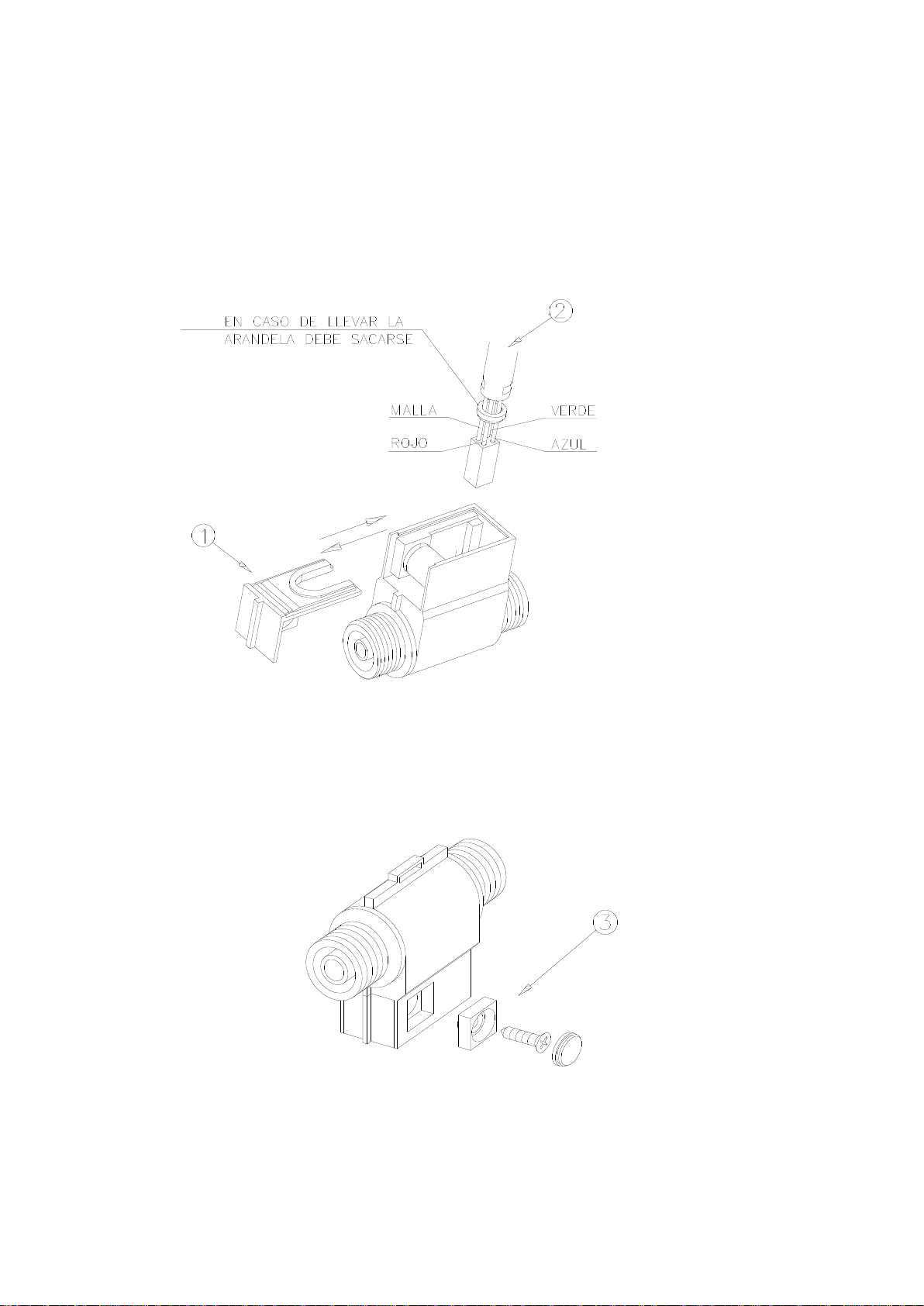
7.2.2. CABLE CONNECTION, COVER CLOSING AND PULSE GENERATOR
SUPPORT
−To connect the pulse generator cable it is necessary to open the pulse generator
cover (item 1) after taking the closing screw out and moving the cover in the right
direction indicated by the arrow. Connect the cable as indicated onitem 2 taking into
account the polarity of the connector.
−Finally put the pulse generator cover back, fix it or seal it, if it is necessary ( item 3)
and place the pulse generator in the corresponding holder.

INSTALLATION MANUAL TX80 SKYGLASS INTERFACOM, S.A.U.
Inst TX80_Skyglass_003_en.doc 17
7.3. SEALING (Drawing 11)
−The pulse generator installation can also be sealed, as shown in the image.
7.4. TECHNICAL CHARACTERISTICS
−The main technical characteristics of the pulse generator are:
−Sensor type: Hall effect cell
−Number of pulses / revolution: 4 with double impulses train
−Feeding voltage: 4 to 18 V
−Consumption at 5 V: 10 mA
8. VEHICLES WITH ELECTRONIC IMPULSE SIGNAL
-The distance signal supplied by the car can be connected in two possible ways:
-By connecting this signal to the Green/White wire on the Power Supply cable
-By using the dedicated impulse generator connector, with a shielded cable, or even
mechanical shield, according to local regulations.
- The adaptation of the signals of the different vehicles is done by an internal electronic
circuit with the following characteristics:
•Histheresys of the input is configurable
•It adapts to different levels
•Optional Pull–up
•Optional Pull–down
•Constante K is adjustable between 500 and 80000 km-1.
- All these adjustments are done from the tariff changer. It is necessary to unseal the
device.
Other manuals for Skyglass TX80
1
Table of contents
Other Taxitronic Measuring Instrument manuals


