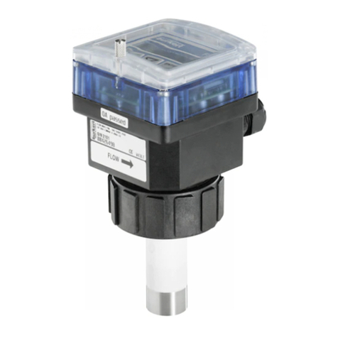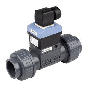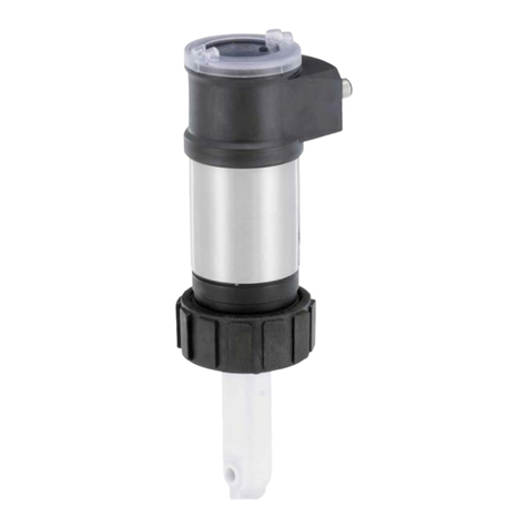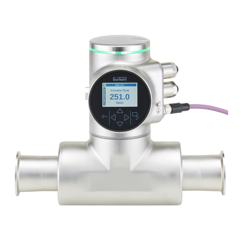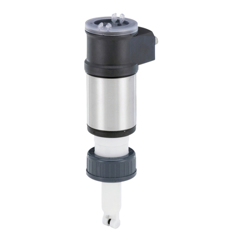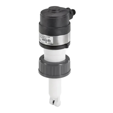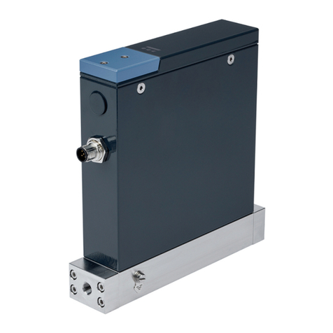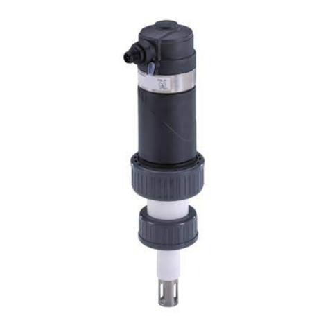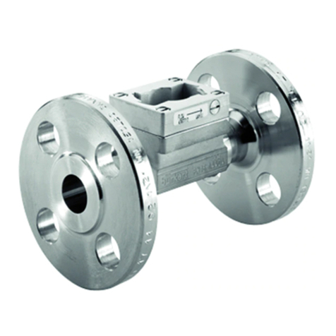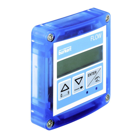
SE36 + S077
2/5
Complete device data (Sensor-fitting S077 + transmitter SE36)
Pipe diameter
Thread connection
Flange connection
DN15...DN100
½"; 1"; 1½"; 2"; 3" (G or NPT)
25; 40; 50; 80 or 100mm DIN PN16 flange
1"; 1½"; 2"; 3" or 4" ANSI 150LB flange
Measuring range
Viscosity > 5mPa.s
Viscosity < 5mPa.s
2...1200l/min (0.53...320gpm)
3...616l/min (0.78...320gpm)
Medium temperature with body
in aluminium / in stainless steel -20...+80°C (-4...+176°F) / -20...+120°C (-4...+248°F)
Medium pressure max.
DN15
DN25 / DN40 or DN50
DN80 / DN100
55bar (798.05 PSI) (threaded process connection)
55bar (798.05 PSI)1) / 18bar (261.18 PSI)
12bar (174.12 PSI) / 10bar (145.1 PSI)
Viscosity 1Pa.s max. (higher on request)
Measurement deviation2) ±1% of the measured value (if “standard” K-factor is used)
±0.5% of the measured value (if “specific” K-factor is used,
on label of the product)
Repeatability ±0.03% of the measured value
Electrical data
Power supply
2 or 3 outputs transmitter (2-wire)
4 outputs transmitter (3-wire)
14...36VDC, filtered and regulated
12...36VDC, filtered and regulated
Characteristics of the power
source (not provided) of UL recog-
nized devices
Limited power source (according to § 9.4 of the UL61010-1
standard) or, Class 2 type power source (according to the
1310/1585 and 60950-1 standards)
Current consumption with sensor
2 or 3 outputs transmitter (2-wire)
4 outputs transmitter (3-wire)
≤1A (with transistors load)
≤25mA (at 14VDC without transistors load, with current loop)
≤5mA (at 12VDC without transistors load, without current loop)
Power consumption 40W max.
Protection Reversed polarity of DC: protected
Voltage peak: protected
Short circuit: protected for transistor outputs
Output
Transistor
1 transistor output
(transmitter 2-wire)
2 transistor outputs
(transmitter 2 or 3-wire)
Current
1 current output
(transmitter 2-wire)
2 current outputs
(transmitter 3-wire)
NPN, open collector, 1...36VDC, max. 700mA
Adjustable as sourcing or sinking (respectively both as PNP
or NPN ), open collector, max. 700mA, 0.5A max. per
transistor if the 2 transistor outputs are wired
NPN-output: 1...36VDC
PNP-output: Power supply
4...20mA adjustable as sourcing or sinking (in the same
mode as transistor),
max. loop impedance: 1100Ω at 36VDC ;
610Ω at 24VDC; 180Ω at 14VDC
max. loop impedance: 1100W at 36VDC;
610Ω at 24VDC; 100Ω at 12VDC
4...20mA output uncertainty ±1%
Standards, directives and certifications
Protection class IP65, IP67 with device wired and M12 cable plug
mounted and tightened and cover fully screwed down
Standards and directives
Pressure (Sensor-fitting S077, DN15...
DN100, in aluminium or stainless steel)
The applied standards, which verify conformity with
the EU Directives, can be found on the EU Type
Examination Certificate and/or the EU Declaration of
conformity (if applicable)
Complying with article4, §1 of 2014/68/EU directive*
Certification (only for SE36)
UL-Recognized for
US and Canada UL61010-1 + CAN/CSA-C22.2 No.61010-1
1) or in accordance to the value of the used flanges.
* F.S. = Full scale (10 m/s)
2) = “measurement bias” as defined in the standard JCGM 200:2012
If the device is mounted in a humid environment or outside, then the maximum allowed
voltages are 35VDC instead of 36VDC.
Materials view
Aluminium or
stainless steel
PPS
EPDM
Silicone
PC
Stainless
steel
Brass,
nickel plated
PC
PPS,
aluminium or
stainless steel
Stainless steel
Top interior view
FKM or
FEP/PTFE
* For the 2014/68/EU pressure directive, the device
can only be used under the following conditions (de-
pends on max. pressure, pipe diameter and fluid).
Type of Fluid Conditions
Fluid group 1,
article4, §1.c.i DN ≤25
Fluid group 2,
article4, §1.c.i
DN ≤32 or
PN*DN ≤1000
Fluid group 1,
article4, §1.c.ii
DN ≤25 or
PN*DN ≤2000
Fluid group 2,
article4, §1.c.ii
DN ≤200 or
PN ≤10 or
PN*DN ≤5000

