Taxitronic TX30 User manual

INTERFACOM, S.A. 22/12/2016
I3000100.DOC 26.02.96
INSTALLATION MANUAL
OF
TAXIMETER
TAXITRONIC TX30

INTERFACOM, S.A.
I3000100.DOC 2
GENERAL INDEX
1. ASSEMBLY
2. ELECTRICAL INSTALLATION
3. SEALING
4. MAINTENANCE
5. TECHNICAL CHARACTERISTICS
6. IMPULSE GENERATOR
7. ADAPTER FOR ELECTRONIC PANNEL

INTERFACOM, S.A.
I3000100.DOC 3
1. ASSEMBLY (Drawing 1)
The mechanical installation of the TX30 taximeter is very simple due to its small
size 180 x 50 x 32 mm.
It can be built in and also assembled directly on the panel or on any type of
bracket. For the assembly there are anchorages for self threading screws on the
rear part, located on the connector cover, that will enable many assembly
possibilities: wether with two screws directly onto the frontal part of the dash
board or on a support or with a unique screw located in the center of the
connector cover. (See drawing 1)
IMPORTANT:
Notice that to assembly the taximeter onto the frontal part of the
dashboard, you do not need any support: the TX30 taximeter was
designed so that it could be assembled by fixing the connector cover
directly to the dashboard, using screws fixed from the inside of the
cover. Then when the cables have been connected to the taximeter,
it is fitted back into the connector cover and the whole installation is
sealed.
The electrical installation connection outlet on the taximeter can be either on the
rear or on the lower part of the equipment, improving and facilitating assembly. It
is most important that no cable nor connection should be visible.
Try to assemble the taximeter on a rigid support with as little vibration as
possible, as in the long run this can cause a break in the contacts.

INTERFACOM, S.A.
I3000100.DOC 4
2. ELECTRICAL INSTALLATION (Drawings 2,3,4 and 5)
The electrical installation of the TX30 taximeter is similar to the one for the
previous models.
To reach the connectors, you only have to remove the CONNECTOR COVER
( First it is necessary to take out the central screw of the three screws that are on
the front of the TX30).
The TX30 has four differentiated connectors: cables and connectors for the
power supply, impulse generator and external lights are supplied with the
equipment; For the data transmission connector, the cables depend on the
external equipment to be connected.
In Drawing 2 the complete electrical installation of the TX30 is explained. The list
of the conectors from the left to the right as seen on Drawing 2 is the following:
EXTERNAL LIGHTS CONNECTOR (8 tracks)
Contact 1............. Light 6
Contact 2............. Light 5
Contact 3............. Light 4
Contact 4............. Light 3
Contact 5............. Light 2
Contact 6............. Light 1
Contact 7............. Position lights (output)
Contact 8............. Common return
FEED CONNECTOR (10 tracks)
Contact 1, 2..............Negative battery ..............................Black
Contact 3,4...............Positive battery 12V.........................Red
Contact 5..................Input................................................Yellow
Contact 6..................Input................................................Blue
Contact 7..................Light 1 .............................................Green
Contact 8..................External signal or passenger...........Violet
Contact 10................External signal.................................Brown
IMPULSE GENERATOR CONNECTOR (4 tracks)
Contact 1....................Ground...................Mesh
Contact 2....................5 V..........................Red
Contact 3....................Signal.....................Green
Contact 4....................Signal.....................Blue
DATA TRANSMISSION CONNECTOR
NOTE: The TX30-S does not have any external lights connector, since it can
control only one external light through the green cable of the feed
connector.

INTERFACOM, S.A.
I3000100.DOC 5
Drawing 3 gives an example of the simplified installation of a taximeter
controlling only an external light “FREE” or ”TAXI”. It also shows the possibility in
the case of a radio-taxi company to use the light connector L6 to inform the
central of the state of the taximeter.
Drawing 4 and 5 gives two examples of installation with a connection box and
armoured cables, which prevent to access to the installation without destroying
the seals of this connection box.
RECOMMENDATIONS FOR THE INSTALLATION OF A TAXIMETER IN A CAR:
Disconnect the positive terminal on the battery until the whole electrical
installation is completed.
Any manipulation of the taximeter or of the external lights must be done with the
taximeter desconnected from the feeding.
Always take the positive and negative of the battery direct in order to avoid false
contacts and to obtain a more filtered feed.
Always connect the cables to the battery by means of a terminal, never by
winding the wires on to the contact.
If the cables cross a plate to reach the taximeter they should go through a
protective rubber casing.
If the cables are too long they should be cut to the required length and not rolled
up under any circumstances.
Please verify that the sparking plug cables are made out of graphite, so that no
interference affect the equipment.
If the vehicle has a radio endeavor to separate its installation from that of the
taximeter as far as this is possible.
Always inspect the earth connection of the aerial and the connectors.
If it is possible no element that is connected to the taximeter should be fixed to
the same support as the aerial of the radio.

INTERFACOM, S.A.
I3000100.DOC 6
EXTERNAL LIGHTS CONNECTOR
If the external lights connector is used, each one of the cables must be welded to
the connector in such a position that they have a good contact:
RECOMMENDATIONS FOR THE PROGRAMMING OF A TAXIMETER IN A CAR:
When the installation of the taximeter in the vehicle is completed proceed to
program it using the tariff charger.
Please always connect the charger in the right position, since a wrong position
may block the microchip of the taximeter and the CPU plate.
The programming sequence is as follows:
The programming is started up with the taximeter in the For Hire
position pressing the O pushbutton in the taximeter.
Calculate the constant K by doing a trial run or introducing it directly.
Adjustment of the calendar-clock if necessary.
Tariff recording.
To have more information, see “Operation Manual for the TX30 Tariff Charger”.

INTERFACOM, S.A.
I3000100.DOC 7
3. SEALING (Drawing 6)
3.1.- SEALS OF THE TX30
The sealing of the taximeter TX30 is totally made on the left of the frontal part of the
taximeter, preventing from reaching the screws that block the accesses.
See details of the taximeter drawing below:
1 2 3
Seal Nº1: corresponds to the sealing of the box of the taximeter. Therefore it
seals the electronic plate.
Seal Nº2: seals the back cover of the connectors, that is, it seals the whole
installation of the taximeter, assembly, as well as electrical installation.
Seal Nº3: seals the cover of the tariff charger connector, which is located just on
the right hand side of this seal.
3.2.- TYPES OF SEALS (Drawing 6)
In order to adapt to all legislations, there are two options of sealing, that can be
used for any of the 3 seals of the TX30 taximeter.
A OPTION: Stamped lead seal and / or plastic seal
- For this type of seal, a flat square has to be used, in which the
stamped lead or plastic seal has to be fitted.
- The sealed screw cannot be reached without breaching the seal.
B OPTION: with seal for cable
- For this type of seal, you have to use a seal plate together with a screw
with a pierced head.
- A cable is passed through the pierced hole of each element and is
then sealed.
- The sealed screw cannot be reached without breaching the cable that
goes through the screw with pierced head.

INTERFACOM, S.A.
I3000100.DOC 8
- In Drawing 6 you can observe different sealing methods:
- Drawing 6, example 1.- Plastic seals and/or stamped lead seals to seal the box
(item1), the connector cover (item 2) and the tarif connector
cover plate (item 3).
- Drawing 6, example 2.- Cable seal to seal the box (item 1), and another to seal
together connector cover and tarif connector cover plate
(item2).
- Drawing 6, example 3.- Combination of plastic and/or lead seals and cable seals.

INTERFACOM, S.A.
I3000100.DOC 9
4. MAINTENANCE (Drawing 7 and 8))
When the TX30 does not work, the box must be opened to substitute the defective
CPU plate with an asistance plate
To open the taximeter box, there are two possibilities:
4.1. opening with the hands
4.2. opening with a tool
4.1.- OPENING WITH THE HANDS (Drawing 7)
It is the normal way to open the box.
As you see on the drawing 7, you have got to take out the screws corresponding to
the box (item 1) and to the connector cover (item 2). Afterwards you can open the
box from the side where there are the seals, following the indicated direction of the
arrows of the drawing.
4.2.- WITH A TOOL (Drawing 8)
In some cases the opening by hand (see above) is not possible because some of
the TX30 have a box that will not allow that.
In this case take the screws out from the front face, take the connector cover down
and process as indicated in Drawing 8.
TO OPEN A TAXIMETER PLEASE:
take into account that even if the taximeter is desconnected from the external
feeding source, the CPU plate is internally fed with a battery and that any short cut
could damage a component.
pay attention not to touch the plate with the hand to prevent the mirco chip to block
itself and consume all the battery.

INTERFACOM, S.A.
I3000100.DOC 10
5. TECHNICAL CHARACTERISTICS
The general technical characteristics of the TX30 are as follows:
Feed voltage nominal = 12 V
maximum = 16 V
minimum = 8 V
Maximum consumption without external lights = 250 mA
Maximum consumption taximeter off = 25 mA
Maximum consumption inside battery = 5 A
Maximum power 36 W for each external light of 60 W in case that 3 outputs are
connected in parallel.
Impulse generator feed = 5 V
Impulse generator inlet signal: level 0 = -1 to 2,5 V
level 1 = from 4 to 25 V
Maintenance of the information disconnected from the vehicle’s battery = 5 years
45 V surges with a duration of 10 ms.
Resistance to electrostatic shocks of 7 kv.
Protection against inverse incorporated connection
Internal protective fuse of 6,3 A and 1 for protecting the CPU of 400 mA.
External fuse of 4 A.
Operational temperature - 20 to +70º C
Storage temperature for keeping the information - 40 to + 85º C
Dimensions 180 x 50 x 32
Approximate weight 204 gr.
"K” constant of the device from 400 until 80000 pulses per Km/ml.
NOTE: For the TX30-S the maximum power for the external light is: 36 W.

INTERFACOM, S.A.
I3000100.DOC 11
6. IMPULSE GENERATOR
6.1.- INTRODUCTION
For the vehicles with mechanical speedometer, you have to use a pulse generator
that is managed by the taximeter.
The pulse generator is inserted in the cable of the speedometer and converts the
mechanical movement of this cable in an electrical signal, which is amplified and
filtered by the taximeter.
6.2.- INSTALLATION (Drawing 9 and 10)
6.2.1. ASSEMBLY OF THE SPEEDOMETER CABLE AND PULSE GENERATOR
(Drawing 9)
First of all part of the protecting cover of this cable must be removed and the cable
must be cut (Drawing 9, item1)
A fixing ring must be put in each of the two extremities of the cable (Drawing 9,
item 2 ) and a square end (Drawing 9 item 3) on both parts that will be fixed by
pressing them on the part indicated in Drawing 9 item 4 with the appropriate pincers
(Drawing 9 item 7) in position “A” or “B“ of depending on the size of the square end.
Afterwards put the cover ends (Drawing 9 item 5) and press them on the part
indicated in Drawing 9 item 6 in the position “C” of the pliers.
Finally all pieces are assembled screwing together the two fixing rings (Drawing 9
item 9) taking into account that the separating space indicated in item 8 Drawing 9
must be sufficient.
6.2.2. CABLE CONNECTION, COVER CLOSING AND PULSE GENERATOR
SUPPORT (Drawing 10)
To connect the pulse generator cable it is necessary to open the pulse generator
cover (Drawing 10 item 1) after taking the closing screw out and moving the cover
in the right direction indicated by the arrow. Connect the cable as indicated on the
Drawing 10 item 2 taking into account the polarity of the connector.
Finally put the pulse generator cover back, fix it or seal it, if it is necessary (Drawing
10 item 3) and place the pulse generator in the corresponding holder (Drawing 10
item 4).

INTERFACOM, S.A.
I3000100.DOC 12
6.3.- SEALING (Drawing 11)
The pulse generator also has got different sealing possibilities. Three of these
possibilities are showed in Drawing 11.
6.4.- TECHNICAL CHARACTERISTICS
The main technical characteristics of the pulse generator are:
sensor type: Hall effect cell
Number of pulses / revolution: 4 with double impulses train
Feeding voltage: 4 to 18 V
Consumption at 5 V: 10 mA

INTERFACOM, S.A.
I3000100.DOC 13
7.- VEHICLES WITH ELECTRONICAL SPEEDOMETER
7.1.- INTRODUCTION
In the case of the vehicles equiped with electronical speedometer, the taximeter can
be connected to these sensors with a sealable adaptor, which ensures the fiability of
the system.
This equipment consists of one circuit which is inserted between the distance sensor of the
car and its speedometer. This circuit gets the signal which is sent by the distance sensor,
sends an identical signal to the speedometer and another signal to the taximeter according to
its input characteristics.
Usually the distance sensor is placed in the gearbox. In some cars, it can also be placed in
the transmission differential.
7.2.- INSTALLATION.
Before connecting the equipment to the car, you have to make the following:
Localize the distance sensor of the vehicle.
Identify the cables that connect this sensor to the car speedometer.
Search which of these cables corresponds to the ground, the power and the
distance signal in order to connect them correctly to the adapter.
Some cars have a cable which has a signal (oscillator) that the sensor uses
like a carrier to modulate it in amplitude.
See which kind of signal sends the sensor to the speedometer to configurate
the adapter jumpers in order it works correctly. Diagram 1 shows the
different signals that adapters can give.
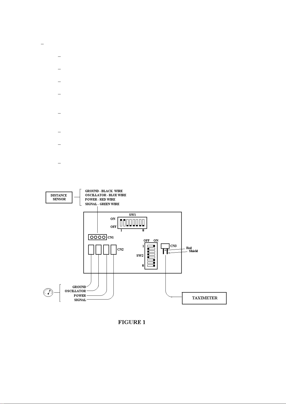
Figure 1 shows the printed circuit of the adapter indicating the jumpers and
connections of the cables to the circuit.
INTERFACOM, S.A.
I3000100.DOC 14
Equipment installation is made as follows:
Disconnect the cable which joins the vehicle sensor to the speedometer by
the side of the sensor. Usually, it is placed in the gearbox.
Put the rubber washer enclosed in the adapter circuit in this cable in order it
remains well fixed.
This cable must be solded in the contacts foreseen in the adapter circuit
(CN2).
These contacts are: Ground, Oscillator, Power and Signal. If the car sensor
does not have one of these signals, the corresponding contacts will
remain empty.
Connect the cable that is delivered with the adapter, to the CN1 connector
and at the other end the distance sensor, making the same contacts that you
have done previously.
Cover the connections made with the thermoretractable cable enclosed and
apply heat to seal it and prevent modifications.
Connect the taximeter to the adapter circuit in connector CN3 by means of
the cable enclosed. The cable must be connected leaving the shield and the
red cables at the top part.
Verify that the taximeter works correctly and adjust the constant "K" of the
taximeter with the tariff charger.

INTERFACOM, S.A.
I3000100.DOC 15
7.3.- JUMPERS CONFIGURATION.
The equipment is configurated with the jumpers in order it can be adapted to the
different sensors which are in the vehicles.
The adapters delivered from the factory are configurated in order to work correctly
with a signal of the following characteristics:
Level 0 < 1,5 v.
Level 1 > 3,5 v.
Hysteresis = 2 v.
The signal can have any shape (Squared, Impulses, Senoydal, Triangular,
etc.) if the levels 0 and 1 are between the values described above.
LEVEL1
LEVEL0
SQUARED IMPULSES TRIANGULAR SINE
D IAG R AM 1
DIFFERENTSSHAPESOFTHESIGNAL:
If the levels 1 or 0 are not the above described, jumper SW2-P8 must be removed
in order the adapter looks for the average value of the signal internally.
If the signal given by the sensor is very weak, jumper SW2-P7 must be removed in
order to reduce the Hysteresis of the circuit.
Jumper SW1-P1 must be only made when the sensor doesn't have the correct
ground, when there are potential differences between the taximeter ground and the
sensor ground.
After having connected the sensor to the adapter circuit as described, we have to
check if the distance signal has still the same tension and if the impulses appear
correctly. If this signal disappears or the tension is not correct you will have to make
the following:
If the signal wire remains fixed in level 0 (between 0 and 1 volts), make jumpers
SW1-P3, SW1-P7 and remove jumper SW1-P2.
If the signal wire is fixed in level 1 (between 5 and 12V), make jumper SW1-P5.
If the signal given by the sensor is moduled in amplitude (diagram 2) jumper SW2-
P1 must be removed and jumper SW2-P2 must be made.

INTERFACOM, S.A.
I3000100.DOC 16
D IAG R A M 2
SIGNALMODULEDINAMPLITUDE
Some vehicles Renault use a coil in distance sensor and then need an oscillator to
operate the coil correctly. To install the adapter in these cars you have to make the
following:
Make jumpers SW1-P1, SW1-P2, SW1-P4, SW1-P6, SW1-P8, SW2-P1
and SW2-P6.
Remove the other jumpers.
Connect the sensor coil in CN1 connector, by one side to the power and by
the other side to the oscillator. Connect the shield of the distance sensor
cable to the ground of CN1.
Connect the signal cable of the pannel in connector CN2. Connect the shield
of the pannel cable to the ground of CN2.
If the constant "K" of the vehicle is bigger than the maximum permitted by the
taximeter, the internal impulses divisor will have to be used. Jumpers configuration
of this diviser is as follows:
Without being divided SW2-P6
Divided by 2 SW2-P3
Divided by 4 SW2-P4
Divided by 8 SW2-P5
Only one of these four jumpers can be made.
Figure 1 shows the standard configuration of jumpers. If any of the jumpers has
been changed and it still does not work, we recommend to put again the standard
configuration before making more proves, because some jumpers configurations
are incompatibles.
7.4.- SEALING (Drawing 12)
The adaptor for electronic pannel has got two sealing possibilities that are showed
in Drawing 12.
Table of contents
Other Taxitronic Measuring Instrument manuals


