Taxitronic TX52 User manual

INTERFACOM, S.A. 09.05.18
Inst TX52_TX40_007_en.doc 15/06/2015
INSTALLATION MANUAL
TAXITRONIC TX52 / TX40

INTERFACOM, S.A.
Inst TX52_TX40_007_en.doc 2
GENERAL INDEX
1. ASSEMBLY
2. ELECTRICAL INSTALLATION
3. SEALING
4. TECHNICAL CHARACTERISTICS
5. IMPULSE GENERATOR
6. VEHICLES WITH ELECTRON IC SIGNAL
INTERFACOM, S.A.
Inst TX52_TX40_007_en.doc 3
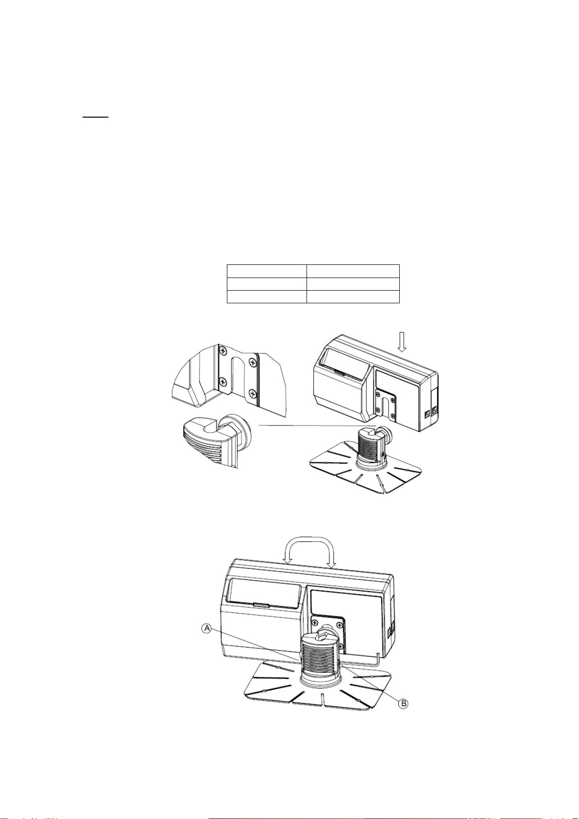
1. MECHANICAL INSTALLATION
TX52 is fixed to the dashboard with an adhesive bracket. If the surface is rough, so adhesive
is not possible, the bracket base can also be fixed to the dashboard with screws
On a taximeter with integrated printer, it is necessary to leave some space on the back side
to allow opening the printer cover, in order to be able to change the paper.
1. The surface must be clean and dry. Clean it with a mix of isopropilic alcohol and water.
2. Take out the adhesive protector, and adhere the bracket with strong and uniform force. If
necessary, bend the flaps to adapt it to the dashboard shape
3. The adhesive resistance increases as it dries..
After 20 min
50%
After 24 h
90%
After 3 days
100%
4. Insert the taximeter onto the bracket, and adjust heighth and orientation
5. Tighten screws A and B to fix the position and orientation.
INTERFACOM, S.A.
Inst TX52_TX40_007_en.doc 4
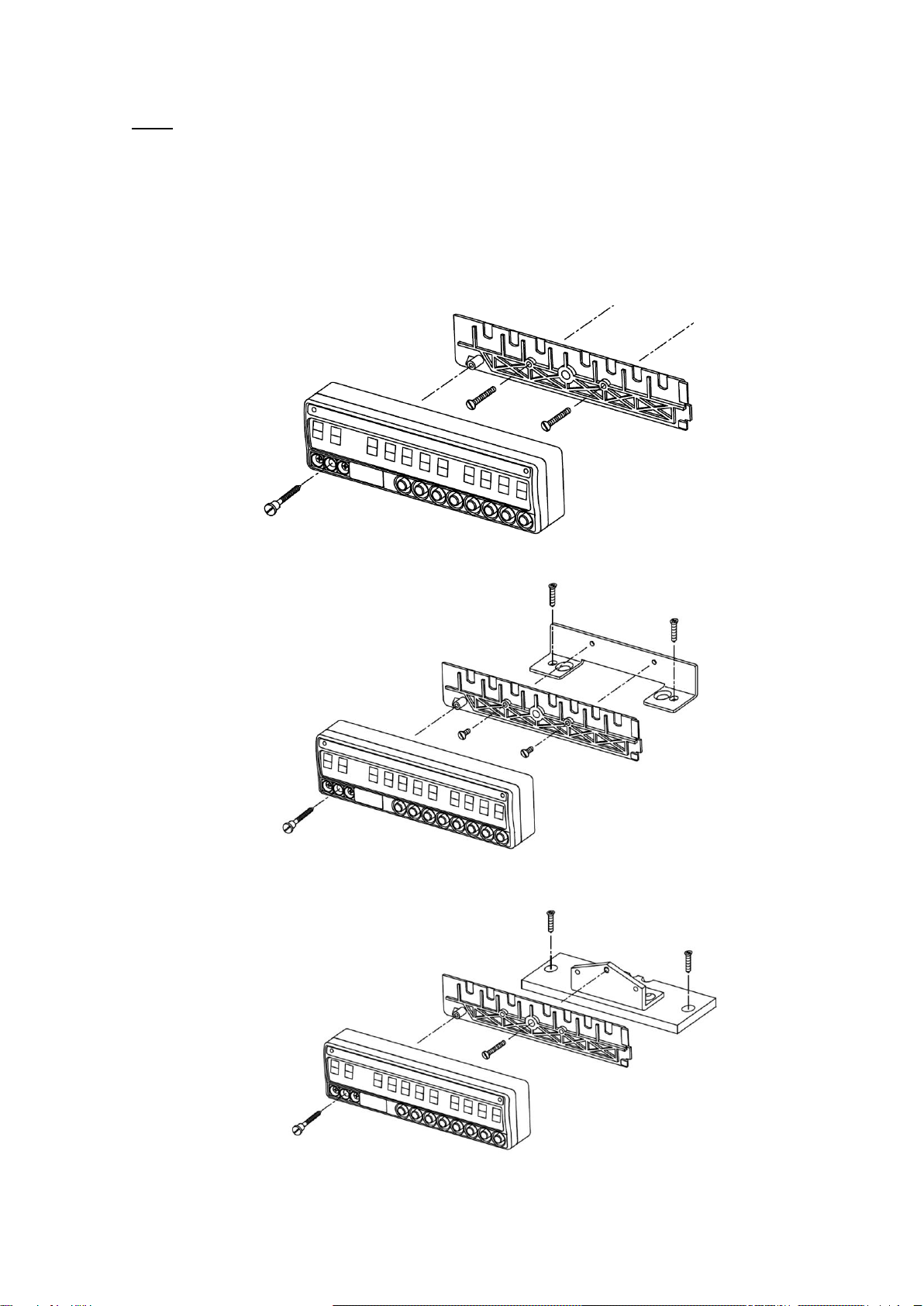
TX40 can be fit directly on the panel, or on many types of bracket.
The connector cover is prepared to make holes for self threading screws, whether with two
screws onto the front of the dashboard, or to a specific bracket
Cables can go out to the back or to the bottom of the device. Leave no cables in sight
Fitting onto a vertical surface
Fitting on top of the dashboard with a bracket
Adjustable tilt bracket

INTERFACOM, S.A.
Inst TX52_TX40_007_en.doc 5
2. ELECTRICAL INSTALLATION
To access the connectors it is necessary to open the Connector cover
-Take out the screw that seals the cover
-On TX52, liberate a clip on the bottom of the taximeter
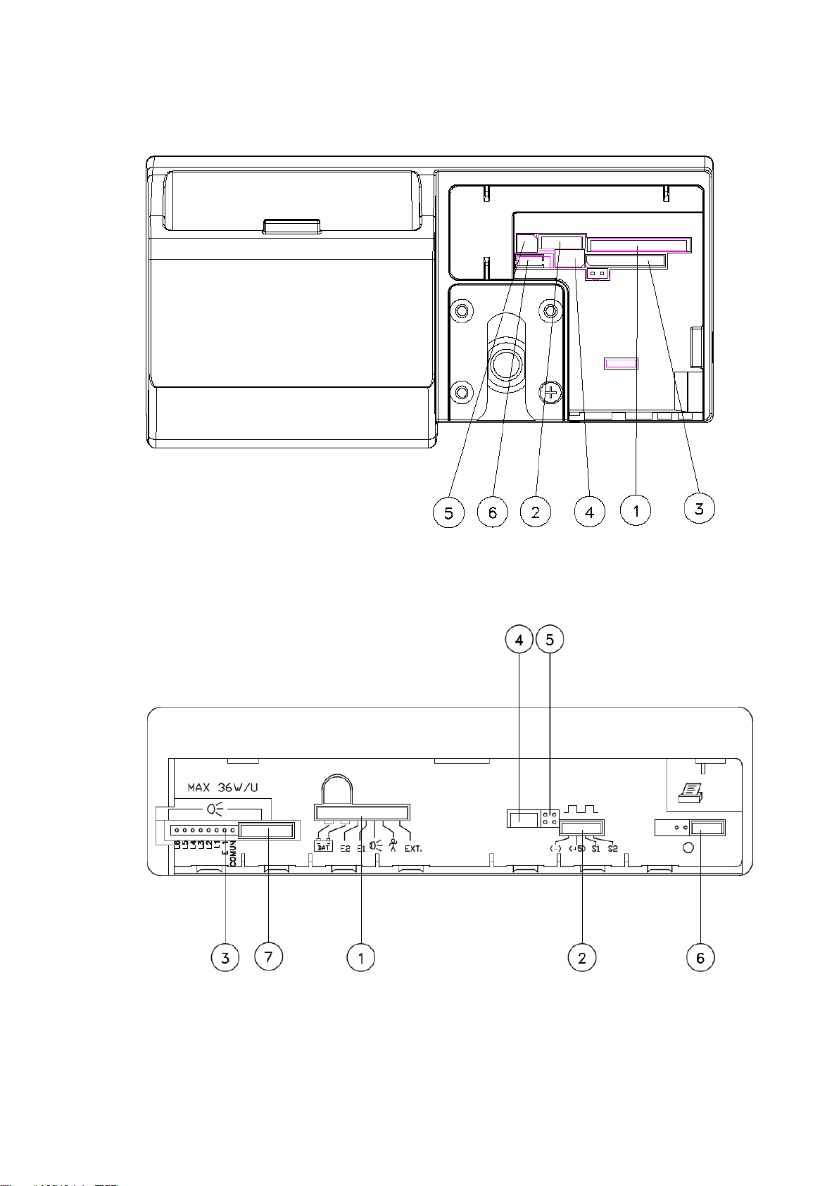
The taximeter has the following connectors:
•(1) Power Supply
Contact number
Color
Function
X = Required
1, 2
Black
Ground
X
3, 4
Red
Battery 12V
X
5
Yellow
Position lights
6
Blue
Contact Key
X
7
Green
Rooflight
8
Violet
Passenger sensor
9
Green / White
Distance pulses
X
10
Brown
External signal
•(2) Impulse Generator
Contact number
Color
Function
1
Mesh
Ground
2
Red
5V output
3
Green
Signal
4
Blue
Complemented signal
•(3) Parallel Rooflight
Contact number
Color
Function
1
Light 6
2
Light 5
3
Light 4
4
Light 3
5
Light 2
6
Light 1 (Free)
7
Position lights output
8
Ground

INTERFACOM, S.A.
Inst TX52_TX40_007_en.doc 6
•(4) Serial Port
Contact number
Function
1
12 V output
2
5 V output
3
TXD
RS232 levels +- 12V
4
TXD
TTTL levels 0 - 5 V
5
RXD
6
Ground
•(5) Serial Rooflight.
The connector on the cable has a white mark, which has to be oriented to serial port. (Tx40)
The connector on the cable has a white mark, which has to be oriented to the bottom. (Tx52)
Contact number
Function
1
2 V output
2
RXD
TTL 0 –5 V
3
Ground
Ground
4
TXD
TTL 0-5 V
5
6
•(6) CAN Bus
Contact number
Function
1
CAN H
2
CAN L
3
Ground
•(7) CAN Bus 2 (TX40 only)
Contact number
Function
1
+ 12V output
2
+ 5V output
3
CAN H
4
CAN L
5
Ground
INTERFACOM, S.A.
Inst TX52_TX40_007_en.doc 7
TX52 CONNECTORS
TX40 CONNECTORS

INTERFACOM, S.A.
Inst TX52_TX40_007_en.doc 8
MINIMUM INSTALLATION

INTERFACOM, S.A.
Inst TX52_TX40_007_en.doc 9
COMPLETE INSTALLATION

INTERFACOM, S.A.
Inst TX52_TX40_007_en.doc 10
RECOMMENDATIONS FOR THE ELECTRICAL INSTALLATION
−Disconnect the positive terminal on the battery until the whole electrical
installation is completed.
−Any manipulation of the taximeter or of the external lights must be done while
the taximeter is disconnected from the power supply
−Always take the positive and negative directly from the battery in order to avoid
false contacts and to obtain a more filtered power supply.
−Always connect the cables to the battery by means of a terminal, never by
winding the wires onto the contact.
−If the cables cross a plate to reach the taximeter they should go through a
protective rubber casing.
−If the cables are too long they should be cut to the required length and not rolled
up under any circumstances.
−If the vehicle has a radio transmitter, separate its installation from that of the
taximeter as far as this is possible.
−If it is possible no element that is connected to the taximeter should be fixed to
the same support as the aerial of the radio.
−If you need to show the SOS alert on the rooflight, you should ask for a special
tariff. Rooflight must be prepared to show SOS signal.

INTERFACOM, S.A.
Inst TX52_TX40_007_en.doc 11
−3. SEALING
3.1. SEALING
−Seal Nº1: Seals the taximeter box, preventing access to the electronic board.
−Seal Nº2: Seals the connectors cover, so it seals the electrical installation.
−Seal Nº3: seals the cover of the tariff charger connector
−On TX52 the sealing is on the sides
−On TX40 the sealing is on the front:
1 2 3
The taximeter kit is normally ready for sealing with a sticker seal. In some regions it is
necessary to have a cable seal. If you need this kind of seal, the taximeter kit should
include an antiturn angle and screws with a hole for the cables

INTERFACOM, S.A.
Inst TX52_TX40_007_en.doc 12
4. TECHNICAL CHARACTERISTICS
The general technical characteristics of TX52 / TX40 are as follows:
−Power supply voltage Nominal = 12 V
Max = 30 V
Min = 8 V
−Maximum consumption without external lights = 1000 mA
−Maximum consumption taximeter off = 10 mA
−Maximum consumption inside battery = 5 A
−Maximum power 36 W for each external light of 60 W in case that 3 outputs are
connected in parallel.
−Impulse generator power supply = 5 V
Impulse generator input signal: level 0 = -1 to 2,5 V
level 1 = from 4 to 25 V
−Maintenance of the information disconnected from the vehicle’s battery = 5 years
−40 V surges of 10 ms.
−Resistance to electrostatic shocks of 6 kv (Contact), 8 kV (Air).
−Protection against inverse connection
−TX52:
−Internal connector protective fuse of 1.85 A.
−Internal electronics protective fuse of 1.5 A.
−Internal battery protective fuse of 0.1 A.
−TX40:
−Internal connector protective fuse of 1.85 A.
−Internal battery protective fuse of 0.1 A.
−External fuse of 4 A.
−Operational temperature:
−TX52: -10 to +70ºC
−TX40: -25 to +70ºC
−Storage temperature for keeping the information - 40 to + 85º C
Wide
High
Deep
TX52C
153
78
59
TX52S
153
72
36
TX40
180
50
32
−"K” constant of the device from 500 until 80000 pulses per Km/ml.
−Mechanical environment M3
−Climatic environment E3
INTERFACOM, S.A.
Inst TX52_TX40_007_en.doc 13
5. IMPULSE GENERATOR
5.1.- INTRODUCTION
−For the vehicles with mechanical speedometer, you have to use a pulse generator
that is managed by the taximeter.
−The pulse generator is inserted in the cable of the speedometer and converts the
mechanical movement of this cable in an electrical signal, which is amplified and
filtered by the taximeter.
5.2.- INSTALLATION
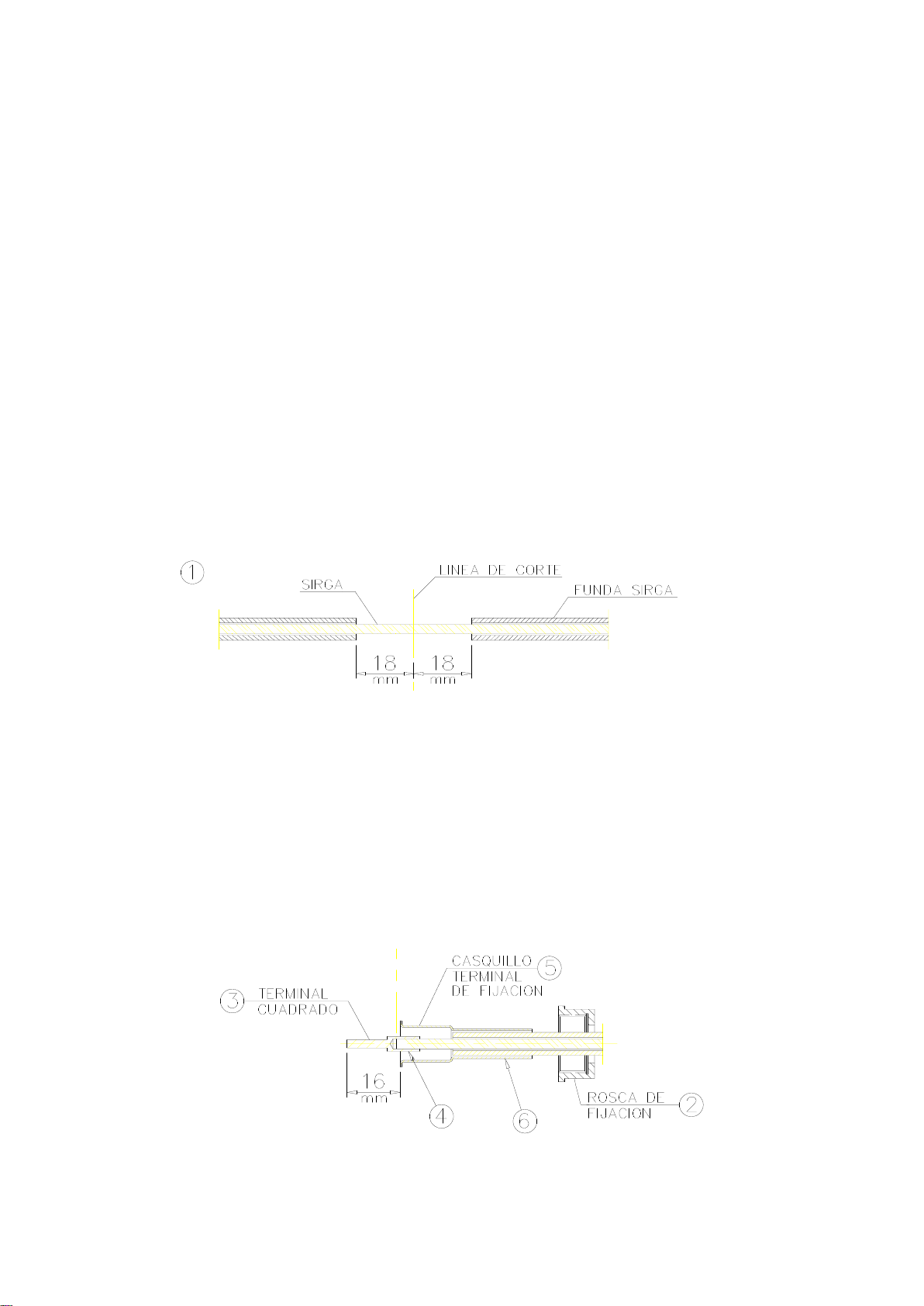
5.2.1. ASSEMBLY OF THE SPEEDOMETER CABLE AND PULSE GENERATOR
−First of all part of the protecting cover of this cable must be removed and the cable
must be cut (item 1)
−A fixing ring (item 2) must be put in each of the two edges of the cable. The square
terminals (item3) are placed on the cable, and are fixed by pressing on the zone
indicated with (4) . This is done in position “A” or “B” of the pliers depending on the
diameter of the square terminal.
−Afterwards put the cover ends (item 5) and press them on the part indicated in item
6 in the position “C” of the pliers.

INTERFACOM, S.A.
Inst TX52_TX40_007_en.doc 14
−Finally all pieces are assembled by screwing together the two fixing rings taking into
account that the separating space indicated by (8) must be sufficient.
INTERFACOM, S.A.
Inst TX52_TX40_007_en.doc 15
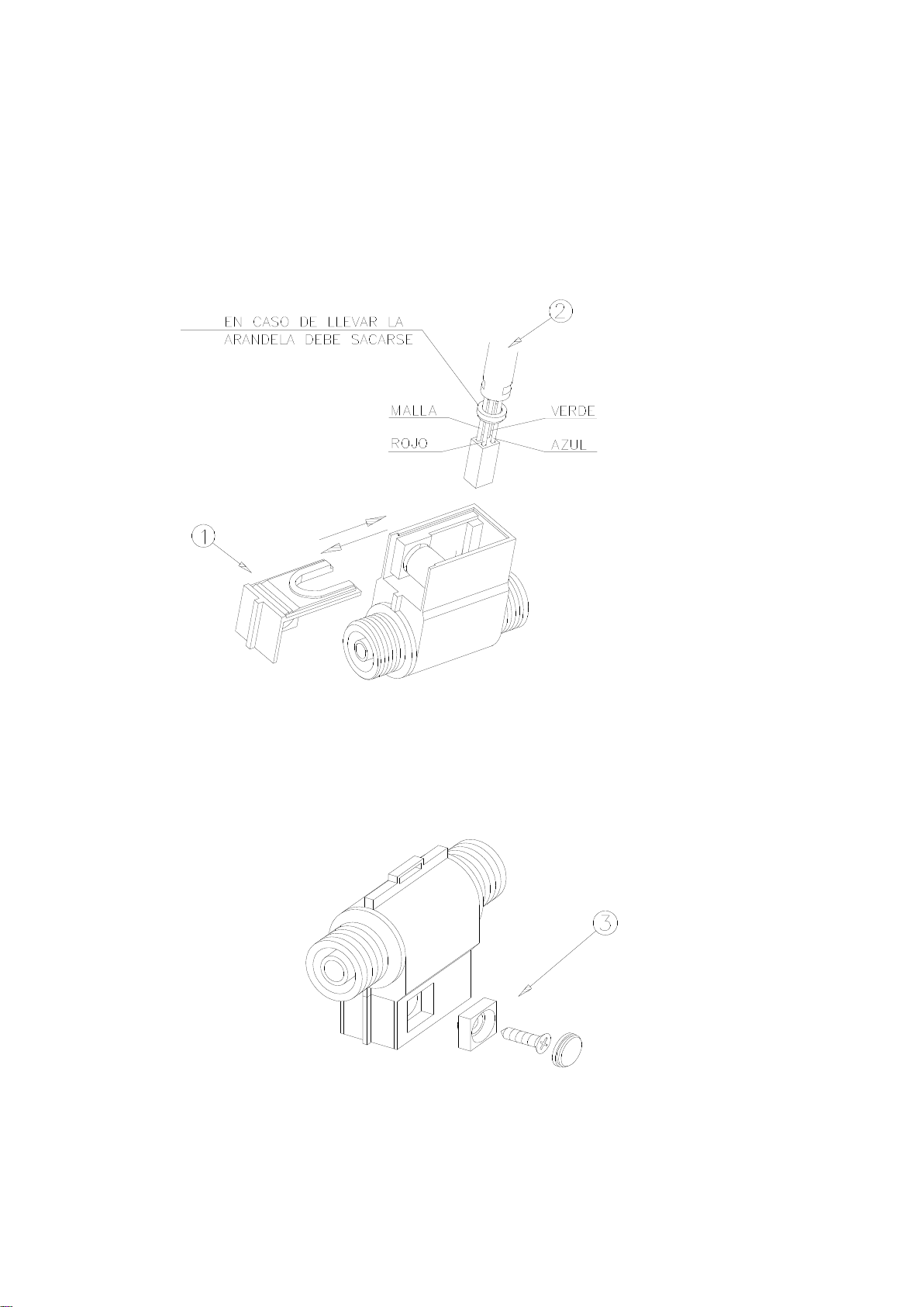
5.2.2. CABLE CONNECTION, COVER CLOSING AND PULSE GENERATOR
SUPPORT (Drawing 10)
−To connect the pulse generator cable it is necessary to open the pulse generator
cover (item 1) after taking the closing screw out and moving the cover in the right
direction indicated by the arrow. Connect the cable as indicated onitem 2 taking into
account the polarity of the connector.
−Finally put the pulse generator cover back, fix it or seal it, if it is necessary ( item 3)
and place the pulse generator in the corresponding holder.
INTERFACOM, S.A.
Inst TX52_TX40_007_en.doc 16
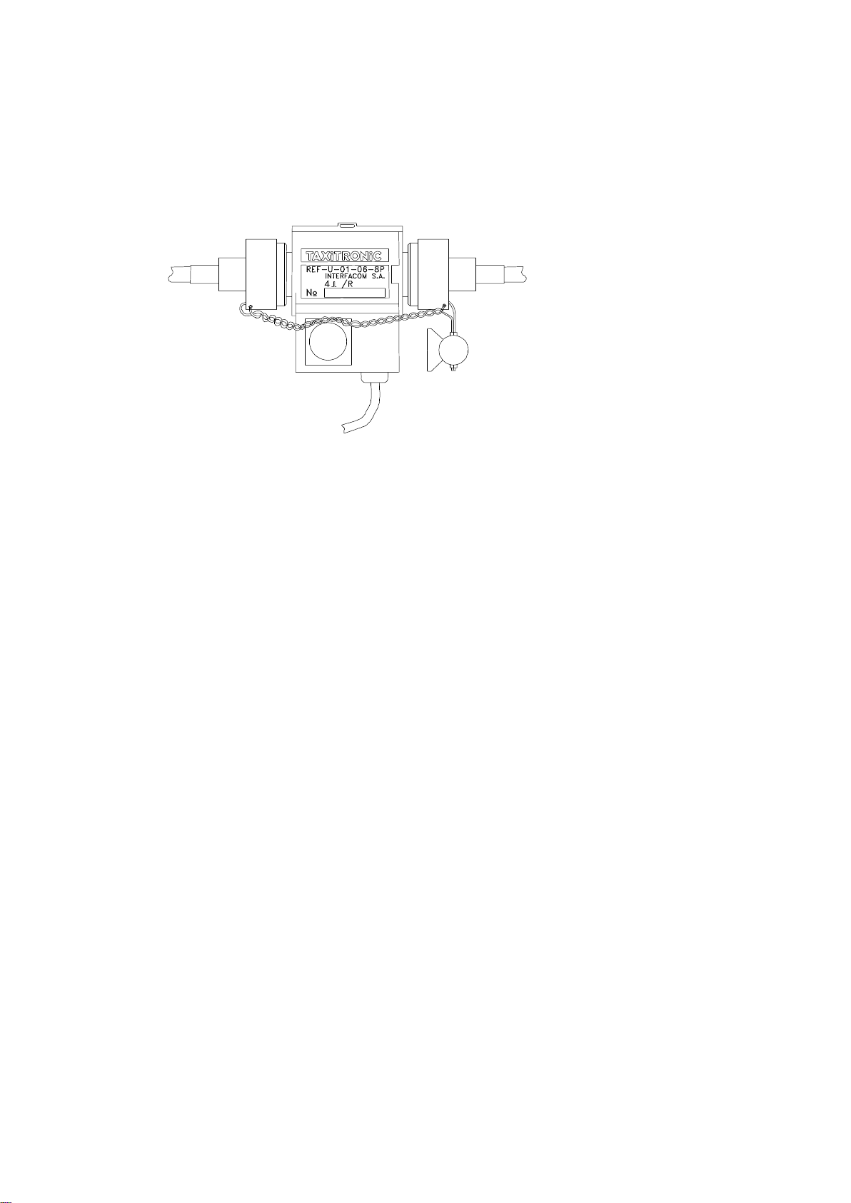
5.3.- SEALING (Drawing 11)
−The pulse generator installation can also be sealed, as shown in the image.
5.4.- TECHNICAL CHARACTERISTICS
−The main technical characteristics of the pulse generator are:
−Sensor type: Hall effect cell
−Number of pulses / revolution: 4 with double impulses train
−Feeding voltage: 4 to 18 V
−Consumption at 5 V: 10 mA
6. VEHICLES WITH ELECTRONIC IMPULSE SIGNAL
-The distance signal supplied by the car can be connected in two possible ways:
-By connecting this signal to the Red/White wire on the Power Supply cable
-By using the dedicated impulse generator connector, with a shielded cable, or even
mechanical shield, according to local regulations.
- The adaptation of the signals of the different vehicles is done by an internal electronic
circuit with the following characteristics:
•Histheresys of the input is configurable
•It adapts to different levels
•Optional Pull–up
•Optional Pull–down
•Constante K is adjustable between 500 and 80000 km-1.
- All these adjustments are done from the tariff changer. It is necessary to unseal the
device.
Other manuals for TX52
1
This manual suits for next models
1
Table of contents
Other Taxitronic Measuring Instrument manuals


